Hindawi Publishing Corporation Mathematical Problems in Engineering Volume 2014, Article ID 426234, 17 pages http://dx.doi.org/10.1155/2014/426234
Research Article Hybrid Particle and Kalman Filtering for Pupil Tracking in Active IR Illumination Gaze Tracking System Jian-nan Chi,1,2 Li-hua Xie,3 Peng-yun Zhang,1 Yi-fang Lu,1 and Guo-sheng Zhang2 1
School of Automation and Electrical Engineering, University of Science and Technology Beijing, Beijing 100083, China Key Laboratory of Operation Safety Technology on Transport Vehicles, Ministry of Transport, Beijing 100088, China 3 School of Electrical and Electronic Engineering, Nanyang Technological University, Singapore 639798 2
Correspondence should be addressed to Jian-nan Chi;
[email protected] Received 19 February 2014; Revised 26 June 2014; Accepted 1 July 2014; Published 30 September 2014 Academic Editor: Yi Chen Copyright © 2014 Jian-nan Chi et al. This is an open access article distributed under the Creative Commons Attribution License, which permits unrestricted use, distribution, and reproduction in any medium, provided the original work is properly cited. A novel pupil tracking method is proposed by combining particle filtering and Kalman filtering for the fast and accurate detection of pupil target in an active infrared source gaze tracking system. Firstly, we utilize particle filtering to track pupil in synthesis triplechannel color map (STCCM) for the fast detection and develop a comprehensive pupil motion model to conduct and analyze the randomness of pupil motion. Moreover, we built a pupil observational model based on the similarity measurement with generated histogram to improve the credibility of particle weights. Particle filtering can detect pupil region in adjacent frames rapidly. Secondly, we adopted Kalman filtering to estimate the pupil parameters more precisely. The state transitional equation of the Kalman filtering is determined by the particle filtering estimation, and the observation of the Kalman filtering is dependent on the detected pupil parameters in the corresponding region of difference images estimated by particle filtering. Tracking results of Kalman filtering are the final pupil target parameters. Experimental results demonstrated the effectiveness and feasibility of this method.
1. Introduction Gaze tracking is the technology to get gaze direction or gaze point on the computer screen through mechanical, electronic, optical, and other methods, which can be classified into two different types called the intrusive and the nonintrusive. Gaze tracking is widely used in various applications [1, 2] such as “human computer interaction for disabled people,” “virtual reality,” “vehicle driver assistance,” “human behavior study.” Recently, gaze tracking based on the analysis of digital video (video oculography (VOG)) is becoming a popular research topic. In VOG system, computer vision is used to capture human face images and detect eye features. From these features, the gaze parameters can be extracted to acquire the gaze direction or gaze points. When human eyeball rotates, namely, gaze direction changes, some eye features such as the corner of the eye remain unchanged. Some other features such as pupil center, however, will change correspondingly. In this case, gaze parameters are produced between the
changed features and unchanged features, which are used for describing gaze change. The VOG gaze tracking technology has aroused increasing interests of professionals in research and development due to its weak interference to people, simple operation, and high accuracy. VOG gaze tracking commonly uses pupil center cornea reflection (PCCR) technique based on the active IR illumination. The PCCR method applies an infrared light source to produce cornea reflection (Purkinje spot) and calculates the vector from cornea reflection to the pupil center in captured images. Therefore, the PCCR method can estimate gaze direction through eye structure model or mapping model [3–6]. Thus, VOG gaze tracking is composed of two components: gaze feature parameter extraction and gaze direction estimation. Eye feature detection in PCCR within VOG system consists of two processes: pupil segmentation and Purkinje location in the neighborhood of pupil. In the existing references, the method of differentiating of bright pupil and dark pupil images is utilized widely in the active illuminator (light
2
Mathematical Problems in Engineering
(a) Dark pupil
(b) Bright pupil
(c) Difference pupil
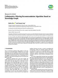
Figure 1: Bright pupil image, dark pupil image, and difference pupil image.
source) system which is made up of two concentric rings of IR LEDS whose center coincides with the camera optical axis [3–5]. The inner ring LED light source is close to the camera optical axis for producing bright pupil image, which is just like “red eye” in some photographs. The LED light source of outer ring is used to produce Purkinje spot on the surface of the user’s eyeball. The inner ring and outer ring LED light alternately to produce bright pupil image and dark pupil image in adjacent frames, which lead to the background elimination via differentiating bright pupil and dark pupil images of adjacent even and odd frames. As a result, pupil is more apparent and easy to be found in the whole face image [6–8]. In differentiating images of bright pupil and dark pupil, threshold method is usually used to segment pupil in local eye region [9–11]. Images of dark pupil, bright pupil, and difference pupil are shown in Figures 1(a), 1(b), and 1(c), respectively. The extraction of gaze parameters within VOG system mostly relies on pupil location, which is accomplished in two adjacent frames of bright and dark pupils. Operational steps for locating the pupil must be repeated in every two bright pupil and dark pupil frames of video sequence to ensure the accurate gaze parameters. But there will be some drawbacks, shown below, if we choose to detect pupil by scanning each whole image. (1) A large amount of required calculation to locate pupil results in the worse real time performance of gaze direction estimation. (2) Since the historical information of pupil motion cannot be used to eliminate the influences of some factors such as eye blinking and external light, it is significantly difficult to extract gaze parameters robustly and get gaze direction estimation accurately. Under some special conditions, such as in the case of eye blinking or eye slightly closed, it is hard to obtain precise pupil parameters by pupil segmentation directly without using the historical information of pupil motion. In order to solve the above two issues, after locating pupil in the initial frame, pupil tracking should be carried out in the following video sequence. Based on pupil tracking results, we can locate and accurately segment pupil to extract pupil parameters. In
video sequences, target tracking can be categorized into two different types. (1) Tracking before detection [12–14]; that is, determine the location of target through tracking algorithm and then finely segment and detect target in the tracking region. (2) Tracking after detection [15]; that is, estimate the detected target parameters through tracking algorithm using the historical information of target, which can get more precisely stable target parameters. Currently, most pupil target tracking algorithms in the gaze tracking system implemented in two adjacent frames focus on the pupil fast detection to determine the location of pupil. This way, which can be called tracking before detection, would result in avoiding detecting pupil in the whole image and improving real-time pupil detection. Pupil tracking can be completed and achieved by various proposed techniques such as Kalman filtering, mean shift, and combination of Kalman filtering and “mean shift” [11, 16, 17]. In reality, the fact is that pupil occurs and moves randomly and often disappears especially in some special conditions like eye blinking, so it is complicated and difficult to build an accurate pupil motion model. Both Kalman filtering and “mean shift” have their own defects to deal with pupil tracking especially under some special condition that we discussed above. Particle filtering is ideal to predict the optimal estimation of a nonlinear and non-Gaussian dynamical system. It can be used to solve the problems of the pupil occlusion and disappearance which are caused by randomness of the eye movement, blinking, and eye closure. For example, Hansen and Pece [18, 19] used particle filtering for iris and pupil tracking. References [20–22] used particle filtering for pupil tracking as well. However, the particle filtering methods above all aim at solving the pupil fast detection, which do not take the pupil shape model and the characteristic of the movement into account. For example, (1) since the shape of pupil is ellipse, the foreground and background cannot be distinguished with a rectangular model; (2) they never consider the geometric similarity of the pupil target ellipse as important clue in the research.
Mathematical Problems in Engineering
3
Outer ring
Image grabbing cards Computer
Inner ring Optical glass filters
GPIO cards Inner ring Outer ring
Active IR light source
Odd frame
Single-chip computer
Focus Even frame Single-chip computer
(a) Real gaze tracking system
CCD camera Optical glass filter Side view
Front view
(b) Sketch map of gaze tracking system
Figure 2: Gaze tracking system.
Real-time pupil tracking is the common problem in the VOG system. The considerations for effective tracking are listed as follows. (1) Since the size of pupil is very small and often influenced by eyelashes and eyelids, one of the most important functions of pupil target model in tracking process is to minimize background interference and distinguish target and background. (2) Because of the random pupil motion which is caused by head movement and pupil rotation, transition equation must always attempt to achieve the detailed characteristics of pupil motion as far as possible. In this paper, a costless and widely used gaze tracking system using PCCR technique is developed for the research. To achieve fast and precise pupil detection, a pupil tracking method based on hybrid of particle filtering and Kalman filtering (HPFKF) in the VOG system is proposed and qualified to meet the requirements as mentioned. The main work in this paper includes the following. (1) Particle filtering is used to track pupil for the fast determination of the accurate pupil location. (2) Kalman filtering is utilized to estimate pupil parameters for pursuing the precision in parameter detection integrated with particle filtering location, which could improve the accuracy and reliability of pupil parameters.
2. Gaze Tracking System and the Initial Pupil Detection Method In this paper, the gaze tracking system is composed of an infrared light source with two concentric rings, optical
glass filters, CCD camera, and image grabbing cards, GPIO (general purpose input/output) cards, single-chip computer, computer, and display screen. There is an inner ring within the infrared light source that produces a bright pupil image when the inner ring is turned on. Alternately, when the outer ring is on, it produces a dark pupil and Purkinje image. When the user watches the screen, the CCD camera obtains face images and sends them to the PC, in which eye features are extracted and eye focus is gotten by gaze mapping function while gaze points are displayed on the screen. To capture the face images that enable this process, the GPIO card is used to obtain the frame alignment signal of the CCD video sequence and employs a single chip microcomputer to control the switch of the light source, activating the inner and outer LED rings alternatively. Gaze tracking system is shown in Figure 2. To estimate the gaze points on the screen, the first step is to detect gaze parameters in image, in which pupil detection plays an important role. In the initial two frames which CCD camera grabbed, the pupil is located firstly and its characteristic parameters are detected. In the following video image sequences pupil tracking is carried out. The scheme of initial pupil detection and characteristic parameters extraction are described as in Figure 3.
3. The Pupil Tracking Based on Combination of Particle Filtering and Kalman Filtering 3.1. Framework of HPFKF. The procedure of parameters extraction proposed in Section 2 is completed in the first two adjacent frames. We capture the pupil in the two initial frames firstly and then perform pupil tracking in the following video sequences.
4
Mathematical Problems in Engineering
Extract two adjacent frames of the video sequence
Recognize the bright and dark pupil image
Get difference image of bright pupil image and dark pupil images
Apply morphology filtering to filter out the spurious noise and reshaping of the boundary of the pupil in difference image
Locate pupil region in difference image and segment pupil
Determine the real pupil by using pupil shape and size analysis; then fit pupil boundary and obtain subpixel center coordinates
Recognize and segment Purkinje around the pupil region and calculate the center of Purkinje spot
Detect and calculate the gaze parameters L = Δx, Δy, 𝛼major /𝛼minor , 𝜃, ic , jc , ip , jp , where (Δx, Δy) represents the vector of the pupil center to corneal reflection,
𝛼major /𝛼minor represents the ratio of major axis to minor axis of the pupil ellipse, 𝜃 represents the angle formed by the major axis of pupil ellipse and the vertical direction, (ip , jp ) represents pupil center, and (ic , jc ) represents corneal reflection.
Figure 3: Sketch map of initial pupil detection.
In this paper it is shown that pupil target estimation is accomplished by the combination of particle filtering [19] and Kalman filtering by using of bright pupil image, dark pupil image and difference image in adjacent frames. The latter process tracks for accurate estimation of pupil parameters, whereas particle filtering tracks for fast location of pupil. The objective of this proposed approach is to improve realtime performance of pupil detection by particle filtering and improve accuracy of pupil parameters detection by Kalman filtering, which is carried out in every two adjacent frames. The flow chart of pupil target tracking method based on the combination of particle filtering and Kalman filtering is shown in Figure 4. During this tracking process, four adjacent frames images (bright pupil, dark pupil, bright pupil, and dark pupil, resp.) are generated by system hardware and defined as follows: the first two frames (bright pupil and dark pupil) are called previous image frame, and the following two frames are called next image frame. Difference image of previous image frame is the subtraction of the bright pupil image and the dark pupil image of the previous image. Difference image of next image frame is the subtraction of the bright pupil image and the dark pupil image of the next image frame. In the initial two
frames of bright pupil and dark pupil image, the following steps are implemented: firstly, find the difference of the bright and dark pupil images; secondly, segment pupil in difference image by use of the pupil detection method introduced in Section 2; thirdly, detect pupil target parameters; and finally, accomplish the tracking initialization. Hence, according to the definition of previous image frame and next image frame, the pupil tracking process is implemented in these resulting images. In previous and next image frames, triple-channel color image is synthesized by bright pupil, dark pupil, and the corresponding difference images. The pupil tracking based on particle filtering is achieved in synthesized color image made from previous image frame and next image frame. According to the detected pupil parameters in previous image frame, we can predict particle state in triple-channel color image synthesized by next image frame. The process of particle filtering pupil tracking can determine the location of pupil. The tracking result based on particle filtering plays a guiding role for the Kalman filtering pupil parameters estimation which is accomplished in the difference image made from previous image frame and next image frames. The Kalman state transition equation of pupil motion is
Mathematical Problems in Engineering
5
Previous image Bright image Dark image of previous of next image image
Bright, dark, and difference images of previous image
Next image Bright image of next image
Parameters detection of the pupil target of previous image
Bright, dark and difference image of next image
The state of the pupil target of previous image (pupil parameters) The state of the pupil target of previous image (color histogram) Pupil parameters detection of bright, dark, and difference images of next image
Pupil target parameter prediction
Dark image of next image
Synthesize threechannel color image of next image
Predict pupil state
Particle optimization Pupil parameters estimation based on Kalman filtering
Pupil target parameters of previous image of next frame
Calculate color histogram
Estimate pupil state
Figure 4: The flow chart of pupil tracking method based on a combination of particle filtering and Kalman filtering.
determined by particle filtering tracking result, which can predict pupil target parameters. According to particle filtering tracking results, pupil can be segmented and pupil parameters can be extracted to serve as observation for the correction of the Kalman prediction above. Finally, the Kalman filtering process can estimate the pupil parameters of next difference image. Tracking result of Kalman filtering is not only the results of final pupil detection, but also the target parameters in the next previous image frame. 3.2. Review of Kalman Filtering and Particle Filtering (1) Particle Filtering. Particle filtering [23, 24] is an approximation algorithm based on Bayesian estimation of sampling theory, which combines sequential Monte Carlo (SMC) method together with the Bayesian theory. Let the state parameter vector of a target at time 𝑡 be denoted by 𝑥𝑡 and its observation by 𝑧𝑡 . The history of observation from time 1 to 𝑡 is denoted by 𝑍𝑡 = [𝑧1 , 𝑧2 , . . . , 𝑧𝑡 ]. The
Bayesian formulation of particle filtering is expressed as 𝑝 (𝑥𝑡 | 𝑍𝑡 ) ∝ 𝑝 (𝑧𝑡 | 𝑥𝑡 ) ⋅ 𝑝 (𝑥𝑡 | 𝑍𝑡−1 ) = 𝑝 (𝑧𝑡 | 𝑥𝑡 ) ⋅ ∫ 𝑝 (𝑥𝑡 | 𝑥𝑡−1 ) ⋅ 𝑝 (𝑥𝑡−1 | 𝑧𝑡−1 ) 𝑑𝑥𝑡−1 . (1) The basic idea of particle filter is to find a set of random samples in the state space of the posterior probability density 𝑝(𝑥𝑡 | 𝑍𝑡 ) approximation and to replace 𝐸[𝑔(𝑥𝑡 | 𝑧𝑡 )] with the sample mean to obtain a state of minimum variance estimate. The key point of implementation of particle filter is to find random samples of obeying the distribution of 𝑝(𝑥𝑡 | 𝑧𝑡 ), which are called particles. 𝑁 sampling points are extracted from the posterior probability density independently, which represented the posterior probability density by the weighted sum. Bayesian importance sampling (BIS) is to use an easy sample of known distribution 𝑞(𝑥𝑡 | 𝑧𝑡 ) to replace posterior probability density for sampling by weighing the sampling
6
Mathematical Problems in Engineering
particles of the importance function to approximate 𝑝(𝑥𝑡 | 𝑧𝑡 ). From the Bayes theory we obtain 𝐸 (𝑔 (𝑥𝑡 )) = ∫ 𝑔 (𝑥𝑡 ) = ∫ 𝑔 (𝑥𝑡 ) =
𝑝 (𝑧𝑡 | 𝑥𝑡 ) 𝑝 (𝑥𝑡 ) 𝑞 (𝑥𝑡 | 𝑧𝑡 ) 𝑑𝑥𝑡 𝑞 (𝑥𝑡 | 𝑧𝑡 ) 𝑝 (𝑧𝑡 ) 𝑤𝑘 (𝑥𝑡 ) 𝑞 (𝑥𝑡 | 𝑧𝑡 ) 𝑑𝑥𝑡 𝑝 (𝑧𝑡 )
∫ (𝑔 (𝑥𝑡 ) 𝑤𝑘 (𝑥𝑡 )) 𝑞 (𝑥𝑡 | 𝑧𝑡 ) 𝑑𝑥𝑡 ∫ 𝑤𝑘 (𝑥𝑡 ) 𝑞 (𝑥𝑡 | 𝑧𝑡 ) 𝑑𝑥𝑡
. (2)
After sampling from the importance function, mathematical expectation of the target state vector is approximated as
Figure 5: Synthesis triple-channel color map.
𝑁
𝐸(𝑔(𝑥𝑡 )) =
(1/𝑁) ∑𝑖=1 𝑔 (𝑥𝑡(𝑖) ) 𝑤𝑘 (𝑥𝑡(𝑖) ) 𝑁
(1/𝑁) ∑𝑖=1 𝑤𝑘 (𝑥𝑡(𝑖) ) 𝑁
(3)
̃𝑘 (𝑥𝑡𝑖 ) , = ∑𝑔 (𝑥𝑡𝑖 ) 𝑤 𝑖=1
(𝑖) ̃𝑘 (𝑥𝑡𝑖 ) = 𝑤𝑘 (𝑥𝑡(𝑖) )/ ∑𝑁 where 𝑤 𝑖=1 𝑤𝑘 (𝑥𝑡 ) is normalized weights (𝑖) and 𝑥𝑡 is a sampling particle from 𝑞(𝑥𝑡 | 𝑧𝑡 ). To overcome the deficiencies of importance sampling, resampling technique is often used for sampling. The basic idea of resampling is to suppress or eliminate small weight particles. Big weight particles are replicated according to their weights. With the dynamic/temporal propagation, particle filtering has been widely used for tracking applications.
(2) Kalman Filtering. Kalman filtering [25, 26] is based on state space model and state space equations of linear dynamical systems, providing a recursive solution of linear optimization filtering. Using the estimated value of the previous time step and the observed value of the current time step to update the target state estimation, we can get the estimated target state value of the current time. Kalman filter is an optimal linear recursive filter according to minimum mean square error rule. Its dynamic system is described by a state equation and observation equation. The state equation is 𝑋𝑘 = Φ𝑘,𝑘−1 𝑋𝑘−1 + 𝑊.
(4)
The observation equation is 𝑍𝑘 = 𝐻𝑘 𝑋𝑘 + 𝑉,
(5)
where 𝑋𝑘 is the state vector in time 𝑘, 𝑌𝑘 is the observation vector in time 𝑘, Φ𝑘,𝑘−1 is the state transition matrix from time 𝑘 − 1 to time 𝑘, 𝐻𝑘 is the measurement matrix in time 𝑘, 𝑊 is state noise vector, and 𝑉 is observation noise vector. Assume that the process noise covariance is 𝑄, the observation noise covariance is 𝑅. Combining the predicted value with measured value of the state, the estimated state value of the current time can be obtained: 𝑋𝑘 = 𝑋𝑘,𝑘−1 + 𝐾𝑔𝑘 (𝑍𝑘 − 𝐻𝑘 𝑋𝑘,𝑘−1 ) 𝑃𝑘,𝑘 = (𝐼 − 𝐾𝑔𝑘 𝐻) 𝑃𝑘,𝑘−1 ,
(6)
where 𝐾𝑔𝑘 = 𝑃𝑘,𝑘−1 𝐻 /(𝐻𝑃𝑘,𝑘−1 𝐻 + 𝑅) is Kalman gain and 𝑃𝑘,𝑘−1 = Φ𝑃𝑘−1,𝑘−1 Φ + 𝑄 is corresponding covariance to 𝑋𝑘,𝑘−1 . The above algorithms constitute the recursive structure of Kalman filtering. 3.3. Pupil Tracking Based on Particle Filtering 3.3.1. Triple-Channel (HSV) Color Map. In order to make the pupil region more apparent in the tracking process, we propose the employment of a synthesized triple-channel color map (STCCM) based on bright pupil image, dark pupil image, and corresponding difference images in which particle filtering pupil tracking can be achieved. STCCM is defined as follows: (1) chrominance of STCCM is equivalent to that of difference image in order to highlight the pupil region color; (2) saturation of dark pupil image is representative of saturation of STCCM; and (3) STCCM brightness is equal to the average brightness of bright pupil and dark pupil images to confirm that the brightness of STCCM is between that of bright pupil and dark pupil images, which prevents significant change in brightness caused by the external light source. Synthesized triple-channel color map is shown in Figure 5. We know that tracking in bright pupil or dark pupil image is difficult, where the pupil feature is not obvious (pupil gray is close to the rest of face). However, STCCM takes full advantage of the triple-channel information, making the color feature of pupil apparent and significantly different from the rest of face. The purpose of the proposed STCCM is to improve the accuracy and stability of pupil tracking. 3.3.2. Pupil Target Model. Pupil target model is established for particle filtering tracking; namely the state of pupil target is described by the vector X𝑡 as follows: X𝑡 = (𝑐𝑥 , 𝑐𝑦 ) ,
(7)
where 𝑐𝑥 , 𝑐𝑦 represent image coordinates of the center of the pupil ellipse.
Mathematical Problems in Engineering
7
(a) STATES𝑡−1
(b) STATES𝑡
Figure 6: STATES𝑡−1 and STATES𝑡 .
3.3.3. Particle Initialization. The initial state of particle [27] is 𝑛 STATES𝑡−1 = { (state𝑛𝑡−1 , 𝜋𝑡−1 ) | state𝑛𝑡−1 = 𝑋𝑡−1 + 𝑉𝑡−1 , 𝑛 𝜋𝑡−1 =
1 }, 𝑁
(8)
𝑛 ) is where STATES𝑡−1 represents the sample set, (state𝑛𝑡−1 , 𝜋𝑡−1 the state and weight of each particle of the set, respectively, and 𝑉𝑡−1 is noise vector. STATES𝑡−1 , that is, state of time 𝑡 − 1, is shown in Figure 6(a).
3.3.4. Particle Selection. According to the weight distribution, randomly select 𝑁 status from STATES𝑡−1 . During filtering, the particles with higher weight have a greater chance of being selected and are chosen more often. Hence, the particles with low weight are eliminated during the selection process: 𝑛 𝑛 ̃ ̃ ̃ 𝑡−1 = {(state STATES 𝑡−1 , 𝜙) | state𝑡−1 ∼ STATES𝑡−1 } .
(9)
3.3.5. Pupil Motion Model. Taking into account the changes of pupil state in a variety of situations, it is possible to establish a simple linear model to describe pupil motion. The law of pupil state movement state𝑛𝑡 is as follows: the elliptical center position of pupil at time 𝑡 is representative of the sum of the elliptical center position of pupil at time 𝑡 − 1 and displacement of the pupil movement. In addition, when the state of particles is predicted, noise vector should be considered. Then we can obtain the equation of the pupil motion: 𝑛 𝑛 ̃ STATES𝑡 = {(state𝑛𝑡 , 𝜙) | state𝑛𝑡 = 𝐴 state 𝑡−1 + 𝑉𝑡−1 } .
(10) By predicting the state of particles according to pupil motion equation, we can get the particle collection STATES𝑡 at current moment 𝑡 as shown in Figure 6(b). 3.3.6. Particle Optimization. After iterations for many times, the weights of many particles are smaller, which means
that the weight variance of the particle is bigger. The target tracking may be inaccurate when the target is estimated by these particles with very small weights. Furthermore, we can see the phenomenon of particle degeneration. Currently, there are three methods to solve this problem: (1) choose the appropriate sampling density function; (2) use the important resample method [28]; and (3) increase the particle number. Reference [20] has proved that the best sampling density function is the posterior probability density function, which is not easy to sample. Generally the sampling density function is represented by the prior probability density which is notably different from the real probability density. The important resampling method that Gordon et al. [29] have proposed can be described as follows: the particles with high weight reproduce the new particle many times, while the smaller weighted particles reproduce fewer particles. As a result, particle variety is reduced. Although the important resampling method can avoid the particle degeneration, it may cause sampling impoverishment. In addition, the method of increasing particle number can increase the computational burden and influence the real-time tracking. In this paper, we use the Camshift [30] algorithm to deal with the problem of particle degeneration. The Camshift algorithm (continuously adaptive mean shift) is a nonparameter iteration technology based on a probability distribution model and uses color histogram to represent the object’s observation model. The purpose of the Camshift method used in particle filtering is to accomplish particle aggregation. In other words, iterated particles will move to the region of the target, which reduce the amount of particles with smaller weight. Even if the particle number is small, it can reflect the target observation model. An experiment in which 20 particles are used to track pupil in 600 image frames is applied to verify the effectiveness of the Camshift based particle optimization method. RMSE (root of mean square error) of tracking results shows that the Camshift based particle optimization method can improve the tracking performance. Figure 7 has shown the tracking results of frames 15, 177, 310, and 544. Table 1 is the experimental results of RMSE, which is the average coordinates of particle states.
8
Mathematical Problems in Engineering
(a) The particle filtering method
(b) The proposed method
Figure 7: The tracking results. Table 1: The experiment results of RMSE. Method RMSE (PF method) RMSE (the proposed method)
15 frames (pixel) 256.031 250.008
177 frames (pixel) 221.181 213.677
Center coordinate = (225.32, 309.41) Major axis = 23.81 Minor axis = 22.74 Orientation = 71.28
310 frames (pixel) 189.594 184.000
544 frames (pixel) 305.321 289.249
350
300 250 200
Center coordinate = (541.25, 302.58) Major axis = 23.15 Minor axis = 22.45 Orientation = 84.52
Figure 8: The initial state of pupil.
3.3.7. Pupil Observation Model. Color distribution is suitable to be used as target model since it is robust and maintains the persistence of nonrigid target deformation, rotation, and scale changes. Thus, we consider the color weighted histogram of pupil region as our observation model. Epanechnikov kernel function highlights the contributions of different pixel to color histogram. The greatest contribution to the color histogram comes from the existence of pixels located at target center, while the smallest contribution occurs at edge region which may contain background. Here we use 𝑑(𝑥) = ((𝑥𝑥 − 𝑐𝑥 )/𝑎major )2 + ((𝑥𝑦 − 𝑐𝑦 )/ 𝑎minor )2 as distance measurement [31], which is known as “gray contour curve distance” and can measure the important weight of the pupil pixel. This means that the smaller the 𝑑(𝑥) is, the greater the pixel weights are. The ellipse curve is composed of pixels of the same 𝑑(𝑥). That is to say, the points of this curve have the same gray value. The 𝑑(𝑥) of pupil ellipse contour is 1, which gradually decreases towards the pupil center until 𝑑(𝑥) is equal to 0, where the “gray contour curve” changes to the center of pupil ellipse. The initial state of pupil and pupil histogram are shown in Figures 8 and 9. During the update procession, we calculate the weighted histogram for each particle and discover that when there are
150 100 50 0
0
10
200
300
500
400
600
Figure 9: Pupil histogram.
similar histograms, there is higher weight. The weight of each particle 𝜋𝑡𝑛 can be calculated based on the weighted histogram 𝐻state𝑛𝑡 of each particle [32]: 𝜋𝑡𝑛 =
1 (−(1−𝜌(𝐻state𝑛 ,𝐻𝑋𝑡−1 ))/2𝜎2 ) 𝑡 . 𝑒 √2𝜋𝜎
(11)
3.3.8. Pupil State Estimation. Pupil target state is estimated by 𝐸 (𝑋𝑡 ) =
𝑛 𝑛 ∑𝑁 𝑛=1 𝜋𝑡 state𝑡 𝑛 ∑𝑁 𝑛=1 𝜋𝑡
.
(12)
Firstly, the histogram 𝐻𝐸(𝑋𝑡 ) of the estimated target is calculated. Then, we get the similarity 𝜌(𝐻𝐸(𝑋𝑡 ) , 𝐻𝑋𝑡−1 ), and finally, we obtain the probability weight 𝜋𝑡𝐸 . If probability weight 𝜋𝑡𝐸 of the estimated target is larger than threshold 𝜋𝑇 , the tracking is considered to be successful, and target state is updated by ratio 𝛼. Contrarily, if the tracking is deemed a failure, then the target state cannot be updated. The tracking result is shown in Figure 10.
Mathematical Problems in Engineering
9 Center coordinate = (230.14, 318.82 Major axis = 24.51 Minor axis = 23.24 Orientation = 75.26
(4) Select particle. According to the weight distribution, select the higher ̃ 𝑡−1 : weight particles from STATES𝑡−1 ; then constitute STATES 𝑛 𝑛 ̃ ̃ ̃ 𝑡−1 = {(state STATES 𝑡−1 , 𝜙) | state𝑡−1 ∼ STATES𝑡−1 } .
(15) Center coordinate = (536.85, 305.55) Major axis = 24.84 Minor axis = 23.62 Orientation = 103.02
Figure 10: Tracking result.
(5) Build pupil motion model. According to pupil motion model, particle state is predicted; it can also describe pupil motion state by using a simple linear model: 𝑛 𝑛 ̃ STATES𝑡 = {(state𝑛𝑡 , 𝜙) | state𝑛𝑡 = 𝐴state 𝑡−1 + 𝑉𝑡−1 } .
(16)
(6) Establish pupil observation model. Calculate the histogram 𝐻state𝑛𝑡 of each particle and then calculate weight 𝜋𝑡𝑛 of each particle based on histogram:
Input image
Eye detection and gaze parameters extraction
𝜋𝑡𝑛 =
1 (−(1−𝜌(𝐻state𝑛 ,𝐻𝑋𝑡−1 ))/2𝜎2 ) 𝑡 . 𝑒 √2𝜋𝜎
(17)
(7) Estimate pupil state: Establish pupil target model and initial tracking
𝐸 (𝑋𝑡 ) =
Particle estimation and particle optimization
Establish pupil observation model
Estimate the new state pupil target
3.3.9. The Estimation Process of Particle Filtering. The flow chart of the pupil tracking based on particle filtering is shown in Figure 11. (1) Synthesize triple-channel color image. (2) Establish pupil model: (13)
(3) Initialize the state of each particle of the set 𝑛 STATES𝑡−1 = { (state𝑛𝑡−1 , 𝜋𝑡−1 ) | state𝑛𝑡−1 = 𝑋𝑡−1 + 𝑉𝑡−1 ,
1 }. 𝑁
.
𝑋𝑡 = (𝑖𝑡 , 𝑗𝑡 , 𝑎major𝑡 , 𝑎minor𝑡 , 𝜃𝑡 , V𝑥𝑡 , V𝑦𝑡 , 𝑎𝑡̇ , 𝜃𝑡̇ ) ,
Figure 11: The flow chart of particle filtering tracking.
𝑛 𝜋𝑡−1 =
𝑛 ∑𝑁 𝑛=1 𝜋𝑡
(18)
3.4. Pupil Tracking Based on Kalman Filtering. After pupil tracking based on particle filtering, we can determine the location of pupil. As shown in Figure 12, the rectangle describes the location of pupil. Next, we segment the pupil in the corresponding pupil region in difference image and attain pupil parameters to be used as observation of next image frame. Kalman filtering [33] is then used to precisely estimate the pupil parameters based on pupil parameters of the previous frame image and the observation of the next frame image. Hence, Kalman filtering tracking is implemented in the difference images. According to the theory of Kalman filtering, we assume that the pupil model in the difference image at time 𝑡 can be represented as follows:
Select particle
𝑋𝑡 = (𝑐𝑥 , 𝑐𝑦 ) .
𝑛 𝑛 ∑𝑁 𝑛=1 𝜋𝑡 state𝑡
(14)
(19)
where 𝑖𝑡 , 𝑗𝑡 are representative of the pupil center coordinates at time 𝑡; then 𝑎major𝑡 , 𝑎minor𝑡 are the major axis and minor axis of the pupil ellipse, respectively. 𝜃𝑡 is the angle between the major axis of pupil ellipse and the vertical direction. V𝑥𝑡 , V𝑦𝑡 represent their respective velocity at time 𝑡 in 𝑥, 𝑦 direction. 𝛼̇𝑡 , 𝜃𝑡̇ signify the rate of change of pupil scale and angle 𝜃𝑡 , respectively. Pupil location estimated by particle filtering at time 𝑡 is (𝑐𝑥𝑡 , 𝑐𝑦𝑡 ). Assuming pupil position parameters estimated in previous image frame being (𝑐𝑥𝑡−1 , 𝑐𝑦𝑡−1 ), we can get V𝑥𝑡 = (𝑐𝑥𝑡 − 𝑐𝑥𝑡−1 )/Δ𝑡 and V𝑦𝑡 = (𝑐𝑦𝑡 − 𝑐𝑦𝑡−1 )/Δ𝑡. The state vector X𝑡 at the next time 𝑡 frame is linearly related to previous state X𝑡−1 by the system motion model as follows: X𝑡 = AX𝑡−1 + W𝑡 .
(20)
10
Mathematical Problems in Engineering
(a) Tracking results under different head poses
(b) Tracking results under different head poses with glasses
(c) Tracking results under blinking
(d) Tracking results under normal condition
Figure 12: Experiment result based on the proposed method.
Here, A is the state transition matrix, W𝑡 represents system perturbation which is normally distributed as 𝑃(𝑊𝑡 ) ∼ 𝑁(0, 𝑄), and 𝑄 represents the process noise covariance. If we assume that observation vector of pupil target is Z𝑡 = (𝑖𝑡 , 𝑗𝑡 , 𝑎major𝑡 , 𝑎minor𝑡 , 𝜃𝑡 ) which is the pupil parameters detected at time 𝑡, we can see that the observation model of the Kalman filtering is Z𝑡 = HX𝑡 + V𝑡 .
(21)
Here matrix H is called “observation matrix,” which represents the relationship between current state and current measurement, while V𝑡 represents measurement uncertainty.
V𝑡 is normally distributed as 𝑝(𝑉𝑡 ) ∼ 𝑁(0, 𝑅), and 𝑅 is the measurement noise covariance. Here H is defined as follows: 1 [0 [ H=[ [0 [0 [0
0 1 0 0 0
0 0 1 0 0
0 0 0 1 0
0 0 0 0 1
0 0 0 0 0
0 0 0 0 0
0 0 0 0 0
0 0] ] 0] ]. 0] 0]
(22)
Given the state transition model (see (20)), the observation model (see (21)) and the initial condition, the state vector X𝑡 and its covariance matrix 𝑃𝑡 can be updated as follows.
Mathematical Problems in Engineering
11
̂𝑡|𝑡−1 be the estimated state at time 𝑡, resulting from Let X ̂𝑡|𝑡−1 is often referred the transition of system state model. X ̂ to as the “prior state estimate.” X𝑡|𝑡 is estimated using both the system model (see (20)) and the measurement model (see (21)) and is usually referred to as the “posterior state estimation.” Let P𝑡|𝑡−1 and P𝑡|𝑡 be the covariance matrices ̂𝑡|𝑡−1 and X ̂𝑡|𝑡 , respectively. These for the state estimates of X matrices determine the uncertainties associated with the prior and posterior state estimates. The Kalman filtering algorithm for state prediction and updating may be summarized below. ̂𝑡−1|𝑡−1 3.4.1. State Prediction. According to estimation state X ̂ and its covariance P𝑡−1|𝑡−1 at 𝑡 − 1 time, X𝑡|𝑡−1 and its covariance P𝑡|𝑡−1 at 𝑡 time can be predicted: ̂𝑡−1|𝑡−1 , ̂𝑡|𝑡−1 = AX X (23)
𝑇
P𝑡|𝑡−1 = AP𝑡−1|𝑡−1 A + Q𝑡 .
(24)
Here, 𝑆𝑡 is the area of the pupil target, while 𝐿 𝑡 is the perimeter. Both of them are described by pixel number. The range of value 𝑅𝑡 is [0, 1], being that the rounder the target is, the larger the 𝑅𝑡 is, and the 𝑅𝑡 value of a standard circle is 1. The shape of the pupil ellipse can be described by circularity. During pupil motion process, both its shape and scale change. Assuming that 𝑅𝑡 is the target circularity of the region that Particle filtering tracked at time 𝑡 and 𝑅𝑡−1 at time 𝑡 − 1, the ratio of 𝑅𝑡 and 𝑅𝑡−1 would be defined as follows: 𝑅 𝑘= 𝑡 . 𝑅𝑡−1
(25)
According to different value of 𝑘, we can get the different state transition matrix:
𝑘 > 1:
0 0 1 0 0 0 0 0 0
0 0 0 1 0 0 0 0 0
0 0 0 0 1 0 0 0 0
Δ𝑡 0 0 0 0 1 0 0 0
0 0 1 0 0 0 0 0 0
0 0 0 1 0 0 0 0 0
0 0 0 0 1 0 0 0 0
Δ𝑡 0 0 0 0 1 0 0 0
0 Δ𝑡 0 0 0 0 1 0 0
0 0 Δ𝑡 0 0 0 0 1 0
0 0 0 Δ𝑡 0 0 ] ] 0 −Δ𝑡 0 ] ] ] 0 0 Δ𝑡] ] 0 0 Δ𝑡] ] 0 0 0] ] ] 1 0 0] ] 0 1 0] 0 0 1]
0 0] ] 0] ] Δ𝑡] Δ𝑡] ]. 0] ] 0] ] 0] 1]
3.4.2. State Updating. Based on particle filtering tracking ̂𝑡|𝑡−1 and its results (Section 3.3), the prior state estimate X covariance matrix P𝑡|𝑡−1 , we can determine the region of the pupil, and therefore we segment the pupil and attain pupil parameters Z𝑡 . We can then perform state updating to derive the final state and its covariance matrix. The first task during state updating is to compute the Kalman gain K𝑡 : P𝑡|𝑡−1 H𝑇 . HP𝑡|𝑡−1 H𝑇 + R𝑡
(27)
The gain K𝑡 can be regarded as a weighing factor when determining the contribution of measurement Z𝑡 and prê𝑡|𝑡 . X ̂𝑡|𝑡 is ̂𝑡|𝑡−1 to the posterior state estimate X diction HX computed as follows: ̂𝑡|𝑡−1 + K𝑡 (Z𝑡 − HX ̂𝑡|𝑡−1 ) . ̂𝑡|𝑡 = X X
4𝜋𝑆 𝑅𝑡 = 2 𝑡 . 𝐿𝑡
0 1 0 0 0 0 0 0 0
0 1 0 0 0 0 0 0 0
(26)
K𝑡 =
Here, A represents state transition matrix. In Section 3.3 of this paper, we can determine the location of pupil by the method of particle filtering. Then, in the corresponding pupil position in the difference image of next image frame, we segment pupil target into binary image and calculate the circularity of the pupil target:
1 [0 [ [0 [ [ [0 [ 𝐴=[ [0 [0 [ [ [0 [ [0 [0
1 [0 [ [0 [ [0 [ 0 < 𝑘 < 1: 𝐴 = [0 [0 [ [0 [ [0 [0
(28)
The a posteriori error covariance estimate is computed as follows: P𝑡|𝑡 = (I − K𝑡 H) P𝑡|𝑡−1 .
(29)
Kalman filtering always produces complete recursive state estimation through the processes of state prediction and measurement updating. Consequently, the posterior estimation at current moment is a priori estimation of next moment.
4. Experimental Results and Analysis 4.1. Results of the Pupil Tracking. In order to prove the validity of the tracking procedure proposed in this paper, we chose 1000 frames consecutive image sequences offered by 3 users for our experiments. An Intel Pentium Dual, CPU E2200 with 2.20 GHz frequency hardware configuration was used to create image of which resolution is 760 by 576 pixels. The experimental circumstances included indoor, cloudy, and normal fluorescent lamp illumination without strong light interference. 1000 frames tracking results of every user are recorded each time. During tracking process, the main purpose is to validate the tracking ability of pupil under various conditions. Figure 12(a) shows the tracking results of frames 169, 468, 715, and 856 under significant facial pose changes. Clearly, it is seen that the proposed method can stably track pupil under the conditions of different head poses. Figure 12(b) shows the tracking results of frames 167, 465, 744, and 955
12
Mathematical Problems in Engineering
(a) Particle filtering method
(b) Direct detection method
(c) The proposed method
Figure 13: Tracking results based on three methods.
The mean square error of the center point position of the pupil target
5 4.5 4 The mean square error
when there are significant face pose changes with glasses. In these situations, if the light glaring on the glasses does not completely occlude the pupils, our method will effectively track pupil. Figure 12(c) shows the tracking effect of frames 166, 310, 519, 767, and 989 under significant face pose changes when blinking. If there is no long time eye closure, or there is no sudden head movement, the proposed method in gaze tracking system can accurately track pupil and meet real-time requirement. Figure 12(d) shows the tracking effect of frames 82, 454, 684, and 946 under normal conditions. These results demonstrate that this method of combining the two tracking techniques produces much better tracking results than using the direct detection method and particle filtering method individually.
3.5 3 2.5 2 1.5 1 0.5 0
4.2. Analysis of Tracking Performance. To illustrate the differences among particle filtering method, direct detection method, and our proposed method, we show the tracking results of these methods under different conditions. As can be seen from Figure 13(a), particle filtering can be used to track the eye during the whole sequence under different conditions, but it is not always successful in detecting the correct eye position. In Figure 13(a), we also can see that particle filtering can only recognize the center of the rectangle range as pupil center, which leads to the center deviating from the pupil center. As shown in Figure 13(b), the direct detection method cannot correctly detect pupil when one is blinking or wearing glasses. In contrast, the proposed method then shown in Figure 13(c) can accurately obtain the pupil center under different conditions. Table 2 shows experimental results of RMSE for the detection of pupil center using three methods (particle filtering, direct detection, and the proposed method). In the experiment, we are able to locate the true center of pupil frame by frame manually and determine the real image
0
250
500
750 1000 Frame number
1250
1500
The proposed method Particle filter method Direct detection method
Figure 14: The RMSE of pupil center.
coordinate of pupil center. From above testing sequences, RMSE between the center of the tracking result and the true center of pupil target can be calculated as shown in Figure 14. In Figure 14, particle filtering and direct detection may be able to track pupil target, but the results are not accurate. In the entire tracking process, the proposed method usually maintains stable and accurate tracking and has a smaller margin of error, which meets the accuracy requirement of the pupil tracking. Figure 15 shows the final gaze point estimation
Mathematical Problems in Engineering
13
Table 2: The pupil parameters and RMSE based on three methods.
User 2 (Figure 14)
User 3 (Figure 14)
User 1 variance (Figure 14) User 2 variance (Figure 14) User 3 variance (Figure 14) User 1 (variance/1500 frames) User 2 (variance/1500 frames) User 3 (variance/1500 frames)
Parameters of detection (#513#690#732#1123)
Parameters of proposed method (#46#221#239#1140)
𝑋: 564, 𝑌: 434
𝑋: 557, 𝑌: 434, major: 9, minor: 10
𝑋: 542, 𝑌: 429, major: 9, minor: 10
𝑋: 524, 𝑌: 434
𝑋: 512, 𝑌: 441, major: 8, minor: 10
𝑋: 532, 𝑌: 438, major: 8, minor: 10
𝑋: 576, 𝑌: 454
𝑋: 599, 𝑌: 467, major: 9, minor: 9
𝑋: 568, 𝑌: 454, major: 9, minor: 9
𝑋: 468, 𝑌: 376
𝑋: 496, 𝑌: 382, major: 9, minor: 10
𝑋: 476, 𝑌: 213
𝑋: 452, 𝑌: 219, major: 7, minor: 8
𝑋: 475, 𝑌: 375, major: 9, minor: 10 𝑋: 492, 𝑌: 206, major: 7, minor: 8
𝑋: 490, 𝑌: 300
𝑋: 497, 𝑌: 284, major: 7, minor: 8
𝑋: 471, 𝑌: 298, major: 5, minor: 5
𝑋: 603, 𝑌: 220
𝑋: 510, 𝑌: 290, major: 7, minor: 7
𝑋: 557, 𝑌: 259, major: 7, minor: 7
𝑋: 322, 𝑌: 234
𝑋: 332, 𝑌: 225, major: 7, minor: 8
𝑋: 674, 𝑌: 340
𝑋: 567, 𝑌: 282, major: 9, minor: 10
𝑋: 386, 𝑌: 203, major: 7, minor: 8 𝑋: 132, 𝑌: 371, major: 8, minor: 8
𝑋: 692, 𝑌: 332
𝑋: 469, 𝑌: 277, major: 9, minor: 9
𝑋: 375, 𝑌: 292, major: 7, minor: 9
𝑋: 636, 𝑌: 192
𝑋: 494, 𝑌: 229, major: 8, minor: 9
𝑋: 368, 𝑌: 305, major: 5, minor: 8
𝑋: 569, 𝑌: 321
𝑋: 565, 𝑌: 328, major: 8, minor: 9
𝑋: 567, 𝑌: 331, major: 8, minor: 9 𝑑: 6.708, 𝑑: 5.657
𝑑: 21.954, 𝑑: 14.318
𝑑: 16.279, 𝑑: 21.514
𝑑: 21.024, 𝑑: 5.318
𝑑: 24.012, 𝑑: 15.524
𝑑: 19.106, 𝑑: 15.811
𝑑: 43.382, 𝑑: 24.597
𝑑: 64.815, 𝑑: 49.930
𝑑: 49.930, 𝑑: 51.264
𝑑: 4.472, 𝑑: 6.708 𝑑: 6.325, 𝑑: 5.000
𝑑: 15.624, 𝑑: 21.128
𝑑: 12.258, 𝑑: 17.174
𝑑: 6.245, 𝑑: 4.123 𝑑: 5.886, 𝑑: 5.241
𝑑: 18.854, 𝑑: 12.853
𝑑: 24.263, 𝑑: 10.254
𝑑: 4.236, 𝑑: 5.851
𝑑: 15.325
𝑑: 20.832
𝑑: 6.254
𝑑: 25.248
𝑑: 42.214
𝑑: 6.432
𝑑: 17.115
𝑑: 15.980
𝑑: 5.304
960 840 720 Y coordinates (pixels)
User 1 (Figure 14)
Parameters of particle filtering (#216#651#1091#1106)
600 480 360 240 120 0
0
120
240
360
480
600
720
840
960 1080 1200
X coordinates (pixels) Gaze estimation Real gaze
Figure 15: The gaze estimation results.
14
Mathematical Problems in Engineering #127
#147
#173
#179
#61
#88
#110
#129
Figure 16: Experimental results of the proposed method.
results on the screen of user 1 based on the proposed method in gaze tracking system described in Figure 2. This paper proposes a framework for target tracking by using particle filter combining with Kalman filtering. It not only meets requirement of the rapid target location with particle filter, but also estimates the parameters of the target with Kalman filtering. The entire framework of this algorithm achieves the rapid target location and accurate detection of pupil parameters. Currently, many literatures also proposed some portfolio tracking methods. In the literature [17], pupil is located with mean shift method firstly, and then the algorithm updates the tracking parameters with Kalman filtering. The literature [34] tracks the target with particle filter combined with mean shift. In order to verify the effectiveness of the method of particle filter combining with Kalman filtering proposed in this paper, we compare our method with the method of the literature [17], the literature [34], and the method of particle filtering. We capture 2 groups of image sequences which includes about 500 frames in each group. We choose 235 frames from each group including normal image and blinking image. The four methods mentioned above are used for tracking pupil target. The tracking results of frames 127, 147, 173, 179 and 61, 88, 110, 129 from each image sequence are shown in Figures 1, 2, 3, and 4. In Figures 1 and 2, the green rectangle is the final results of our method, which is updated by Kalman filtering. The red rectangle is the results before Kalman filtering updating. Figures 3 and 4 are the results by using particle filtering and using
the method of particle filtering combined with mean shift, respectively. Figures 1 and 3 show that when the tracking error is relatively larger by using particle filter, our method can obtain the more accurate results. During the tracking process, the robustness of our method is also better. Figure 2 shows the results of Kalman filtering combined with mean shift, which use the method mean shift firstly for target location and then use Kalman filtering to update the parameters of the tracking target. For the pupil tracking, the results of the method of Kalman filtering combined with mean shift are not better than the method we proposed but are better than the other two methods. For more complex target tracking problem, the effect of the proposed tracking method where particle filtering is combined with Kalman filtering will be far superior to the method where Kalman filtering is combined with mean shift (see Figures 16, 17, 18, and 19). The results of the method of particle filtering combinedwith mean shift are shown in Figure 4. In this method the local peaks of all particles are gotten by using mean shift; then the tracking process is calculated together with the original particles and processed particles. But the experimental results show that the tracking accuracy of this method is not very nice. This is because some particles have offset the original particle states, which make the calculated location farther away from true position. But the number of particles used in this method is less than that of other methods, in which only 50 particles can achieve better results while the number of other methods is 200. The results of these tracking methods are shown in
Mathematical Problems in Engineering
#127
#61
15
#147
#88
#173
#110
#179
#129
Figure 17: Experimental results of the method of Kalman filtering combined with mean shift.
#127
#147
#173
#179
#61
#88
#110
#129
Figure 18: Experimental results of particle filtering.
16
Mathematical Problems in Engineering #127
#147
#173
#179
#61
#88
#110
#129
Figure 19: Experimental results of the method of particle filter combined with mean shift. Table 3: Comparison of pupil tracking results and positioning time. Parameter Image classification Image number Accurate tracking number Success rate (%) The average success rate (%) Positioning time (ms/frame)
Kalman + mean shift Normal Wink 224 11 218 2 97.32 18.18 93.62 38
Particle filter Normal Wink 224 11 199 6 88.84 54.55 87.23 51
Table 3. We can see that the results of the proposed method are better than those of other combination methods [17, 34].
5. Conclusions In this paper, we proposed a method of pupil tracking in a gaze tracking system based on the combination of particle filtering and Kalman filtering when we oriented to fast and accurate pupil target detection using an active infrared source gaze tracking system. In order to make the color feature of the pupil more prominent, we synthesize triple-channel color image by using the bright pupil image, dark pupil image, and difference pupil image. Particle filtering is applied for fast pupil tracking by using triple-channel color image. On the basis of the tracking results of particle filtering, we use Kalman filtering to attain more accurate pupil parameters in difference image. Experimental results and analysis verify and illustrate the effectiveness of the proposed method.
Particle + mean shift Normal Wink 224 11 169 7 75.44 63.63 74.89 49
Our method Normal Wink 224 11 219 8 97.77 72.73 96.59 46
Conflict of Interests The authors declare that there is no conflict of interests regarding the publication of this paper.
Acknowledgments The work is supported by Beijing Key Discipline Development Program (no. XK100080537), the Beijing Natural Science Foundation (4122050), and the Opening Project of Key Laboratory of Operation Safety Technology on Transport Vehicle, Ministry of Transport, China.
References [1] T. Duchowski, Eye Tracking Methodology: Theory and Practice, Springer, New York, NY, USA, 2003.
Mathematical Problems in Engineering [2] R. J. K. Jacob, “The use of eye movements in human computer i nteraction techniques: what you look at is what you get,” ACM Transactions on Information Systems, vol. 9, pp. 152–169, 1991. [3] K. R. Park, J. J. Lee, and J. Kim, “Gaze position detection by computing the three dimensional facial positions and motions,” Pattern Recognition, vol. 35, no. 11, pp. 2559–2569, 2002. [4] Z. Zhu and Q. Ji, “Novel eye gaze tracking techniques under natural head movement,” IEEE Transactions on Biomedical Engineering, vol. 54, no. 12, pp. 2246–2260, 2007. [5] Y. J. Ko, E. C. Lee, and K. R. Park, “A robust gaze detection method by compensating for facial movements based on corneal specularities,” Pattern Recognition Letters, vol. 29, no. 10, pp. 1474–1485, 2008. [6] C. Dong-Chan and K. Whoi-Yul, “Long-range gze tracking system for large movements,” IEEE Transactions on Biomedical Engineering, vol. 60, no. 12, pp. 3432–3430, 2013. [7] H. Lee, S. Y. Lim, I. Lee, J. Cha, D. Cho, and S. Cho, “Multimodal user interaction method based on gaze tracking and gesture recognition,” Signal Processing: Image Communication, vol. 28, no. 2, pp. 114–126, 2013. [8] C. H. Morimoto, D. Koons, A. Amir, and M. Flickner, “Pupil detection and tracking using multiple light sources,” Image and Vision Computing, vol. 18, no. 4, pp. 331–335, 2000. [9] Y. Ebisawa, “Improved video-based eye-gaze detection method,” IEEE Transactions on Instrumentation and Measurement, vol. 47, no. 4, pp. 948–955, 1998. [10] A. de Santis and D. Iacoviello, “Robust real time eye tracking for computer interface for disabled people,” Computer Methods and Programs in Biomedicine, vol. 96, no. 1, pp. 1–11, 2009. [11] Q. Ji and X. J. Yang, “Real time visual cues extraction for monitoring driver vigilance,” Computer Vision Systems, vol. 2095, pp. 107–112, 2001. [12] Z. Lin, Y. Zhou, and W. An, “Improved multitarget track-beforedetect using probability hypothesis density filter,” Journal of Infrared and Millimeter Waves, vol. 31, no. 5, pp. 475–480, 2012. [13] F. Lehmann, “Recursive bayesian filtering for multitarget trackbefore-detect in passive radars,” IEEE Transactions on Aerospace and Electronic Systems, vol. 48, no. 3, pp. 2458–2480, 2012. [14] S. J. Davey, N. J. Gordon, and M. Sabordo, “Multi-sensor track-before-detect for complementary sensors,” Digital Signal Processing, vol. 21, no. 5, pp. 600–607, 2011. [15] A. Zhu, C. Zhang, L. Lv, Y. Liu, and A. Duan, “Dual-module data fusion for detect before track based particle filter,” in Proceedings of the 2nd International Conference on Intelligent Control and Information Processing (ICICIP ’11), pp. 729–731, IEEE, Harbin, China, July 2011. [16] Z. Zhu, F. Kikuo, and Q. Ji, “Real-time eye detection and tracking under various light conditions,” Eye Tracking Research & Applications, vol. 10, pp. 139–144, 2002. [17] Z. Zhu and Q. Ji, “Robust real-time eye detection and tracking under variable lighting conditions and various face orientations,” Computer Vision and Image Understanding, vol. 98, no. 1, pp. 124–154, 2005. [18] D. W. Hansen and R. I. Hammoud, “An improved likelihood model for eye tracking,” Computer Vision and Image Understanding, vol. 106, no. 2-3, pp. 220–230, 2007. [19] D. W. Hansen and A. E. C. Pece, “Eye tracking in the wild,” Computer Vision and Image Understanding, vol. 98, no. 1, pp. 155–181, 2005. [20] T. Liu and S. Zhu, “Eyes detection and tracking based on entropy in particle filter,” in Proceeding of the 5th International
17
[21]
[22]
[23] [24]
[25]
[26] [27]
[28]
[29]
[30]
[31]
[32]
[33]
[34]
Conference on Control and Automation (ICCA ’05), vol. 2, pp. 1002–1007, IEEE, Budapest, Hungary, June 2005. R. Campos, C. Santos, and J. Sequeira, “Eye tracking system using particle filters,” in Proceedings of the IEEE 3rd Portuguese Meeting in Bioengineering (ENBENG ’13), pp. 1–4, IEEE, Braga, Portugal, February 2013. K. Nummiaro, E. Koller-Meier, and L. van Gool, “An adaptive color-based particle filter,” Image and Vision Computing, vol. 21, no. 1, pp. 99–110, 2003. Z. Zhu, Paritcle Filtering and Its Application, Science Press, Beijing, China, 2010. M. Morshidi and T. Tjahjadi, “Gravity optimised particle filter for hand tracking,” Pattern Recognition, vol. 47, pp. 194–207, 2014. Z. Chen, Bayesian Filtering: From Kalman Filers to Particle Filters, and Beyond, McMaster University, Hamilton, Canada, 2003. S. Haykin, Ed., Kalman Filtering and Neural Networks, John Wiley & Sons, New York, NY, USA, 2001. C. Zhang, J. Chi, Z. Zhang, and Z. Wang, “Research on eye tracking method in gaze tracking system,” Acta Automatica Sinica, vol. 36, no. 8, pp. 1051–1061, 2010. V. S. Zaritskii, V. B. Svetnik, and L. I. Shimelevich, “Monte-Carlo technique in problems of optimal information processing,” Automation and Remote Control, vol. 36, no. 3, pp. 2015–2022, 1975. N. J. Gordon, D. J. Salmond, and A. F. M. Smith, “Novel approach to nonlinear/non-gaussian Bayesian state estimation,” IEE Proceedings F: Radar and Signal Processing, vol. 140, no. 2, pp. 107–113, 1993. G. R. Bradsik, “Real time face and object tracking as a component of a perceptual user interface,” in Proceedings of the 4th Workshop on Application of Computer Vision, pp. 214–219, IEEE Computer Society Press, Washington, DC, USA, 1998. R. Valenti and T. Gevers, “Accurate eye center location and tracking using isophote curvature,” in Proceedings of the 26th IEEE Conference on Computer Vision and Pattern Recognition (CVPR ’08), pp. 1–8, Anchorage, Alaska, USA, June 2008. Y. Chu, H. Mi, and Z. Ji, “Image registration based on weighted histogram for digital subtraction angiography,” Acta Electronica Sinica, vol. 36, no. 7, pp. 1344–1348, 2008. H. You, W. Guohong, L. Dajin, and P. Yingning, Multi-sensor data fusion and its application [M.S. thesis], Press of Electronics Industry, 2000. C. Shan, T. Tan, and Y. Wei, “Real-time hand tracking using a mean shift embedded particle filter,” Pattern Recognition, vol. 40, no. 7, pp. 1958–1970, 2007.
Advances in
Operations Research Hindawi Publishing Corporation http://www.hindawi.com
Volume 2014
Advances in
Decision Sciences Hindawi Publishing Corporation http://www.hindawi.com
Volume 2014
Journal of
Applied Mathematics
Algebra
Hindawi Publishing Corporation http://www.hindawi.com
Hindawi Publishing Corporation http://www.hindawi.com
Volume 2014
Journal of
Probability and Statistics Volume 2014
The Scientific World Journal Hindawi Publishing Corporation http://www.hindawi.com
Hindawi Publishing Corporation http://www.hindawi.com
Volume 2014
International Journal of
Differential Equations Hindawi Publishing Corporation http://www.hindawi.com
Volume 2014
Volume 2014
Submit your manuscripts at http://www.hindawi.com International Journal of
Advances in
Combinatorics Hindawi Publishing Corporation http://www.hindawi.com
Mathematical Physics Hindawi Publishing Corporation http://www.hindawi.com
Volume 2014
Journal of
Complex Analysis Hindawi Publishing Corporation http://www.hindawi.com
Volume 2014
International Journal of Mathematics and Mathematical Sciences
Mathematical Problems in Engineering
Journal of
Mathematics Hindawi Publishing Corporation http://www.hindawi.com
Volume 2014
Hindawi Publishing Corporation http://www.hindawi.com
Volume 2014
Volume 2014
Hindawi Publishing Corporation http://www.hindawi.com
Volume 2014
Discrete Mathematics
Journal of
Volume 2014
Hindawi Publishing Corporation http://www.hindawi.com
Discrete Dynamics in Nature and Society
Journal of
Function Spaces Hindawi Publishing Corporation http://www.hindawi.com
Abstract and Applied Analysis
Volume 2014
Hindawi Publishing Corporation http://www.hindawi.com
Volume 2014
Hindawi Publishing Corporation http://www.hindawi.com
Volume 2014
International Journal of
Journal of
Stochastic Analysis
Optimization
Hindawi Publishing Corporation http://www.hindawi.com
Hindawi Publishing Corporation http://www.hindawi.com
Volume 2014
Volume 2014