Hindawi Publishing Corporation International Journal of Reconfigurable Computing Volume 2014, Article ID 243835, 9 pages http://dx.doi.org/10.1155/2014/243835
Research Article Scalable Fixed Point QRD Core Using Dynamic Partial Reconfiguration Gayathri R. Prabhu, Bibin Johnson, and J. Sheeba Rani Department of Avionics, IIST, Thiruvananthapuram 695547, India Correspondence should be addressed to J. Sheeba Rani;
[email protected] Received 15 August 2014; Revised 16 November 2014; Accepted 20 November 2014; Published 14 December 2014 Academic Editor: Neil Bergmann Copyright © 2014 Gayathri R. Prabhu et al. This is an open access article distributed under the Creative Commons Attribution License, which permits unrestricted use, distribution, and reproduction in any medium, provided the original work is properly cited. A Givens rotation based scalable QRD core which utilizes an efficient pipelined and unfolded 2D multiply and accumulate (MAC) based systolic array architecture with dynamic partial reconfiguration (DPR) capability is proposed. The square root and inverse square root operations in the Givens rotation algorithm are handled using a modified look-up table (LUT) based Newton-Raphson method, thereby reducing the area by 71% and latency by 50% while operating at a frequency 49% higher than the existing boundary cell architectures. The proposed architecture is implemented on Xilinx Virtex-6 FPGA for any real matrices of size 𝑚 × 𝑛, where 4 ≤ 𝑛 ≤ 8 and 𝑚 ≥ 𝑛 by dynamically inserting or removing the partial modules. The evaluation results demonstrate a significant reduction in latency, area, and power as compared to other existing architectures. The functionality of the proposed core is evaluated for a variable length adaptive equalizer.
1. Introduction Adaptive equalizers form an inevitable block within receiver’s in general wireless communication systems to reduce the errors caused by intersymbol interference. An important factor that determines the efficiency of the equalizer is the number of filter taps, which should match with the number of channel taps. A fewer number of taps than the actual number of channel taps lead to lower accuracy, whereas a larger number of taps lead to greater power consumption without any benefit of added accuracy. Also, the channel characteristics are more likely to vary in a wireless scenario due to the movement of the users, the intrusion of obstructions, and so forth. Hence, to maintain a balance between the accuracy and the power, the equalizer should also be capable of adapting its number of taps depending on the channel conditions. In [1], the author discusses different methods based on the dynamic computation of the SNR values to determine the optimum number of filter taps with varying channel conditions. An implementation of adaptive filtering is complex due to the algorithms involved. The standard RLS algorithm involves computing matrix inverse at each step which causes
numerical instability issues. Also, the computational complexity of finding the inverse of an 𝑛 × 𝑛 matrix using the direct method is 𝑂(𝑛3 ) which increases with the order of the matrix. Though the LMS algorithm is easy to implement, the convergence rate is much slower compared to the RLS algorithm. A 𝑄𝑅 decomposition based method for RLS with a back substitution technique resolves these issues since it avoids a direct matrix inversion and has the convergence rate on a par with the RLS algorithm. 𝑄𝑅 decomposition of a matrix decomposes it into product of an orthogonal (𝑄) and an upper triangular matrix (𝑅) which simplifies the inverse into multiplication by a transposed matrix and a back substitution operation. There are different algorithms and architectures proposed in the literature which includes Gram-Schmidt orthogonalization, modified Gram-Schmidt orthogonalization [2, 3], Givens rotation [4–11], householder transformations [12], and various other hybrid methods [13, 14]. Gram-Schmidt (GS) algorithm offers reduced accuracy and stability in fixed precision environment. Householder (HH) transformation suits well the dense matrices, but it is difficult to carry out parallel implementations, since its working on the entire
2
International Journal of Reconfigurable Computing
column each time. Givens rotation (GR) has the capability of selectively annihilating individual matrix elements. An error analysis for computing the inverse of a 4 × 4 matrix in fixed point environment is done for GS, HH, and GR in our previous work [15]. Of these, Givens rotation has better performance compared to other methods even with lesser number of bits. Due to its lower error [15, 16], parallel nature, and ease of hardware implementation [9], GR based 𝑄𝑅 decomposition is chosen in this work. Hardware based implementations are required for any of the real time applications such as image and video processing and communication systems, where time forms an important constraint. Also, the area and power are the critical factors which decide the cost of implementation. For the variable length adaptive equalizer considered in this work, there is a requirement to change the size of the QRD core as the channel taps vary. This is achieved using the concept of dynamic partial reconfiguration rather than replicating the structures for each channel size thus saving area and power. In literature, ASICs, dedicated DSP processors, and FPGAs are used as hardware platforms for implementing the design. The runtime reconfigurability feature and the presence of embedded resources of FPGA allow adapting hardware resources to meet time varying requirement. This paper proposes an FPGA based scalable systolic array architecture for 𝑄𝑅 decomposition based on Givens rotation algorithm using the concept of LUT based NewtonRaphson method for inverse square root and square root and achieves scalability using DPR. DPR allows for the reconfiguration of the parts of FPGA while the rest of the device is still functioning and active. The major benefit of partial reconfiguration is the time sharing of the resources thereby achieving considerable area and power savings with a reduced reconfiguration time. The rest of the paper is organized as follows. Section 2 discusses background and related work. The proposed scalable QRD architecture is detailed in Section 3. Section 4 deals with the results and implementation of the proposed core for a variable length equalizer. Finally, the conclusion and future work are given in Section 5.
2. Background and Related Work Consider matrix 𝐴 such that 𝐴 = 𝑄 ⋅ 𝑅,
(1)
where 𝑄 is an orthogonal matrix and 𝑅 is an upper triangular matrix. The Givens rotation algorithm is a recursive method which uses a rotation matrix (𝐺) to transform a given matrix into an upper triangular one. The nonzero entries of 𝐺 matrix are given by 𝑔𝑘𝑘 = 1,
𝑘 ≠ 𝑖, 𝑗,
𝑔𝑖𝑖 = cos 𝜃, 𝑔𝑗𝑗 = cos 𝜃, 𝑔𝑖𝑗 = sin 𝜃, 𝑔𝑗𝑖 = − sin 𝜃,
𝑗 < 𝑖.
(2)
Premultiplying the matrix 𝐴 with 𝐺 affects only the rows 𝑖 and 𝑗 of the matrix 𝐴 and the element 𝐴(𝑖, 𝑗) is made zero with cos 𝜃 =
sin 𝜃 =
𝑎𝑖𝑗 √𝑎𝑖𝑖2
+ 𝑎𝑖𝑗2
𝑎𝑖𝑖 √𝑎𝑖𝑖2
+ 𝑎𝑖𝑗2
,
(3)
,
(4)
and 𝑎𝑖𝑖 value is updated as √𝑎𝑖𝑖2 + 𝑎𝑖𝑗2 . If more than one entry in 𝐴 needs to be zeroed, then an equivalent number of appropriate 𝐺 matrices have to be formed and premultiplied with the matrix 𝐴. Once the required elements are zeroed, the 𝑄 and 𝑅 matrices are obtained as follows: 𝑄 = 𝐺1𝑇 𝐺2𝑇 𝐺3𝑇 𝐺4𝑇 𝐺5𝑇 𝐺6𝑇 , 𝑅 = 𝑄𝑇 𝐴.
(5)
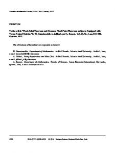
The peculiarity of Givens rotation algorithm is that it uses the first column of the matrix to find the angle of rotation and this angle is used by the rest of the columns for rotation. That means there is a regular pattern involved in computing the 𝑄𝑅 decomposition. This makes it easier to map the algorithm to a systolic array based architecture containing two different processing elements as shown in Figure 1. The main difference between the systolic array architectures proposed in the literature is in the processing elements. The processing elements involve multiplication, division, square root, and inverse square root operations. A direct implementation of these operations in the hardware involves large amount of resources and higher latency. To overcome these, many methods are discussed in the literature which approximates these functions using LUT based log domain arithmetic [2, 3, 7], LUT based Newton-Raphson [4, 5], CORDIC based architectures [9], and so forth. In [8], the square root operation is approximated using CORDIC and inverse square root is done by division. Implementation of the division operation and the CORDIC requires higher latency and consumes more area. In [4, 5], the division operation is replaced by an LUT based Newton-Raphson method. CORDIC based systolic array utilizes vectoring and rotation mode which requires proper selection of scale factor and number of iterations. To solve for the area constraint, control logic based designs are developed which reuses the resources with reduced throughput. Parameterized control logic based architecture [10], folded systolic array based architecture [17], and CORDIC core based architecture [6] are some of the architectures discussed in the literature, which can be made scalable by changing the control logic. In this work, a 16-bit fixed point scalable QRD architecture is proposed by utilizing LUT-N method for square root and inverse root logic. The proposed architecture is made scalable using DPR which reduces the area and power consumption, thus improving the throughput.
International Journal of Reconfigurable Computing
3 C1
C2
C3
C8
BC11
IC12
IC13
···
IC18
BC22
IC23
···
IC28
BC33
···
IC38
Cosine Sine
ain
.. .
.. .
BC77
IC78
ICXX-internal cell BCXX-boundary cell
Mult. Mult.
BC88
(a) 8 × 8 QRD core
Sub. Add
ain
aout Delay r(k − 1)
Cosine
Mult. Mult.
Add (b) Internal cell NR
1/r(k)
r2 (k)
x
Address Control Memory logic (LUT)
NR iteration equation Initial guess
1/√x
sqrt logic
Delay r2 (k − 1)
Mult.
Delay
Sine
r(k − 1)
(c) Boundary cell
(d) Newton-Raphson method
Base address generator Shifter logic
Index address generator
x(n) Address generator
Memory
Mult.
≫1
Add
y ≫1
Threshold value generator (e) NR control logic
(f) NR iteration equation
Figure 1: Block diagram representation of static 𝑚 × 8 QRD core.
3. Proposed Scalable QRD Architecture Figure 1 depicts the 𝑚 × 8 (𝑚 ≥ 8) QRD core with 𝐶1, 𝐶2, 𝐶3, 𝐶4, 𝐶5, 𝐶6, 𝐶7, 𝐶8 as the corresponding column inputs of the matrix, which has to be decomposed. There are mainly two types of processing elements present in the 2D MAC based systolic array: boundary cell (BC) for calculating the angle of rotation and the internal cell (IC) for performing the rotation operation. The processing element used for angle calculation is present only on the left most side of each row in systolic array (because for each row in the systolic array, the column containing the corresponding diagonal element is considered as the first column).
3.1. Boundary Cell. Boundary cell (BC) is responsible for the calculation of cosine and sine values which would be used by the internal cell for rotation operation. Computing the trigonometric functions involves square root and inverse square root operations (4). In [4, 5], the inverse square root is calculated using an LUT based NR method and the square root is computed based on CORDIC logic. In this work, we propose a method to compute the square root values from inverse square root values at the expense of just a delay and a multiplier. The proposed logic is based on the fact that each iteration of Givens rotation depends on the previous iteration. Also, from (4) and the equation updating the 𝑎𝑖𝑖 value, it can be observed that the numerator and denominator used in
4
International Journal of Reconfigurable Computing
computing the sine values are just the delayed versions. Using these two facts together with the mathematical concept, √𝑥 =
𝑥 , √𝑥
(6)
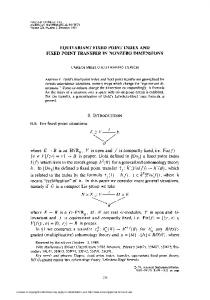
a modified boundary cell (from [4, 5]) is proposed (Figure 1(c)) which computes the square root utilizing the same LUT and NR blocks (square root is computed by delaying the input value sufficiently and then multiplying it with its inverse square root value obtained from NR logic), thus reducing the resource utilization. LUT-N method consists of a control logic, LUT blocks, and NR iteration equation. Since Newton’s method is an iterative technique, the accuracy of the final result is determined by two factors: the number of iterations and the initial guess value. The accuracy of the result is determined by the number of iterations whereas rate of convergence depends on initial value chosen. Also, the hardware implementation of an iterative algorithm has serious effects on the amount of resources utilized and the latency. A folded architecture has high latency, since available resources are utilized in a time sharing manner. In the case of an unfolded architecture, resource consumption will increase with the number of iterations. An unfolded architecture is more preferred for any iterative technique since a proper choice of the initial value ensures higher accuracy within a single iteration. In this method, the initial guess values for Newton’s method are generated and stored within the LUT [4, 5]. A parallel and pipelined control logic has been developed to map the inputs to the initial guess values (Figure 1(d)). The control logic (to generate the address to the LUT) is developed by making use of the binary representation of the values corresponding to which the inverse square root values are stored within the LUT. The LUT is divided into various blocks (each with 3 entries) depending on the number of zeros preceding the first 1. The block number is assigned as the base address for the corresponding initial guess. Using the 3 bits following the first “1,” the offset from the base address is calculated. Adding up the base address and the offset address gives the actual address to the initial guess value. After performing a systematic analysis of different available paths in the data flow graph, the critical path is identified and marked with red lines in Figure 1(e). Feed-forward cut-sets are used for breaking the critical path by introducing pipeline registers. The maximum number of pipeline stages is limited by the amount of latency acceptable to the system. Another feed-forward critical path exists within the unfolded architecture for Newton’s equation (Figure 1(f)) which includes the series of 2 multipliers. These paths are pipelined suitably to meet the timing requirements. 3.2. Internal Cell. The internal cell (IC) receives the trigonometric functions from the boundary cell and performs rotation operation on the inputs. These cells are currently implemented using multipliers and adders (Figure 1(b)). The critical path for the entire QRD core lies within the internal cell which includes an adder and a multiplier in a feedback
loop. Because of the feedback loop in the system, feedforward cut-sets are not feasible to achieve any further increase in the clock frequency. In order to reach the iteration bound [18] (give the maximum theoretical sample frequency), the multiplier block is internally pipelined to increase the clock speed (fine grain pipelining). Only single stage pipelining is possible within the cell, since further pipelining changes the functionality of the block. 3.3. Scalable QRD Architecture. Scalability is introduced into the QRD core using the concept of dynamic partial reconfiguration. The modular based DPR method divides the FPGA into static and dynamic partitions (Figure 2), where the dynamic partition can be adapted at run-time according to the user application without creating any integrity issue for other parts of the FPGA. Instead of having separate QRD cores for different sizes, based on the requirement, the size of core can be varied using the reconfigurable modules (RM). 3.3.1. Static Module. The static module contains internal cells and boundary cells enough to handle matrices of size 𝑚 × 4, where 𝑚 ≥ 4. The entries 𝐶1, 𝐶2, 𝐶3, 𝐶4 in Figure 2 represent the corresponding columns in the matrix which has to be decomposed by the QRD core. 3.3.2. Reconfigurable Modules. The reconfigurable partition in Figure 2 can be occupied by any of the reconfigurable modules RM1, RM2, RM3, or RM4 which makes the implementation 𝑚 × 𝑛 core with 𝑛 = 5, 6, 7, 8 and 𝑚 ≥ 𝑛, respectively. The number of interfaces between the static and the reconfigurable partition is such that they take into account the largest reconfigurable module that has to fit in the reconfigurable partition, in this case the one for 𝑚 × 8 matrix. Whenever a smaller RM is considered, the unused interfaces are tied to zero internally. As from Figure 2, it can be noticed that the number of internal cells and boundary cells increases linearly with the size of the matrix to be handled.
4. Results and Discussion Performance of the proposed scalable QRD core in terms of functionality, resource utilization, power, and latency is analysed step by step on a Virtex-6 FPGA. Further, the developed core has been tested for a variable length equalization where the number of taps can be varied from 4 to 8. Input data to the QRD core is represented using 16bit signed fixed point representation, with 1 bit for sign, 1 bit for integer, and 14 bits for fraction; hence, the range of values would be [−1.999, 1.999]. The hardware architecture is developed using Xilinx System Generator and error analysis is carried out in MATLAB. 4.1. Processing Elements. The input to the QRD core passes through a multiplier and an adder before it reaches the LUTN logic as depicted in Figure 1. Hence, the range of the input values to the LUT-N is [0, 3.999] (square of the input range to the QRD core). The initial guess values for LUT-N method are stored within a block RAM and are used for solving
International Journal of Reconfigurable Computing C1
C2
C3
BC11
IC12
BC22
5 C4
C5
C6
C7
C8
IC13
IC14
IC15
IC16
IC17
IC18
IC23
IC24
IC25
IC26
IC27
IC28
BC33
IC34
IC35
IC36
IC37
IC38
BC44
IC45
IC46
IC47
IC48
BC55
IC56
IC57
IC58
BC66
IC67
IC68
ICXX-internal cell
BCXX-boundary cell 4 × 4 static partition
RM1
RM2 BC77
IC78
RM3 BC88
RM4 Dynamic partitions
Figure 2: Block diagram representation of module based partial reconfiguration for the scalable QRD core.
LUT values 3 2.5 2 1.5 1.25 1 0.75 0.625 0.5
Q2.14 1100000000000000 1010000000000000 1000000000000000 0110000000000000 0101000000000000 0100000000000000 0011000000000000 0010100000000000 0010000000000000
Absolute error
Table 1: A section of input values corresponding to values stored in LUT.
0.01 0.009 0.008 0.007 0.006 0.005 0.004 0.003 0.002 0.001 0
Error analysis for isqrt and sqrt
0
0.5
1
1.5
2
2.5
3
Input value Inverse square root Square root
Figure 3: MSE plot for LUT-N based inverse square root and square root logic.
Newton’s equation. The initial guess values stored in the LUT are generated using the MATLAB code discussed in [4, 5]. The first value of the LUT corresponds to the inverse square root of 3 (as shown in Table 1). In this implementation, the range of the inputs to the LUT-N method is restricted to [0, 3] to avoid errors at larger values of input. The proposed method is compared with two different implementations from the literature (CORDIC method [8], NR + CORDIC method [4, 5]) for finding square root (sqrt) and inverse square root (isqrt) as mentioned in the Table 2. The error analysis for these blocks is carried out by passing 20, 000 random values generated from MATLAB
as inputs to these blocks. The mean squared errors in the results between the hardware implementation and MATLAB in built command for increasing values of inputs are plotted in Figure 3. Spikes occur in Figure 3 because for smaller input values the difference in the initial guess value and the actual value is large. These can be suppressed either by increasing the number of iterations for Newton’s method [4, 5] or by increasing the number of levels in the LUT which would further increase the latency and resource requirements.
6
International Journal of Reconfigurable Computing Table 2: Implementation results for square root and inverse square root logic.
Method
Proposed method
NR + CORDIC method [4, 5]
CORDIC method [8]
160 160
296 556
877 978
4 1 5
3 1 10
1 0 41
Operating frequency (MHz) Mean error for isqrt
351.865 3.4 × 10⁻³
234.917 3.4 × 10⁻³
200.88 1.4 × 10⁻³
Mean error for sqrt
6.1 × 10⁻³
1.6 × 10⁻⁴
1.6 × 10⁻⁴
Slice registers Slice LUTs DSP48Es BRAMs Latency
Table 3: Implementation results for the processing elements. Boundary cell
Internal cell
Type
Fine grain pipelining
Register in path
Resources Slice registers
289
Slice LUTs DSP48Es BRAMs
209 5 1
17 2 0
17 2 0
220.43 11
177.35 1
161.773 1
The square root and inverse square root blocks are integrated with required number of multipliers to form the boundary cell. The internal cell logic is implemented using multiplier and adder blocks. From the results in Table 3, it can be observed that fine grain pipelining helps in improving the speed of operation and resource utilization. Hence, for the rest of the implementations, fine grain pipelined internal cell is used. 4.2. Variable Length Adaptive Equalizer Using Scalable QRD Core. Different instances of boundary cell and internal cell are created and connected as shown in Figure 2 to develop the QRD core. Functionality of the developed core is verified by passing MATLAB generated random matrices as inputs. Also, the error analysis for static implementations of the QRD core for different matrix dimensions (from 𝑚 × 4 to 𝑛 × 8 with 𝑚 ≥ 4 and 𝑛 ≥ 8) was completed in system generator. MSE plot for square matrices of different dimensions is plotted in Figure 4. The computation time for 4 × 4 𝑄𝑅 decomposition using MATLAB in PC with Intel Xenon 3.07 GHz multicore is 2.8 msec, whereas the same with scalable QRD core of size 4 × 4 running on Virtex-6 FPGA is 0.291 𝜇sec. From the MSE plot for the matrices, it can be observed that the error increases linearly for the increasing matrix dimensions which is due to the accumulation errors of Givens rotation algorithm. As an initial test case, the static portion of the proposed core has been used for a QRD-RLS based adaptive equalizer as shown in Figure 5. The modulation scheme used is a basic BPSK with the simulation (transmission) environment as a random channel in presence of AWGN noise. Since, in order
32
MSE plot for different matrix dimensions
0.014 0.012 0.01 MSE
Operating frequency (MHz) Latency
Number used 0
0.008 0.006 0.004 0.002 0
4
4.5
5
5.5 6 6.5 Matrix dimension
7
7.5
8
Figure 4: MSE plot of QRD for different matrix dimensions.
to avoid overflow, the application considered involves a train of sequence to be passed (also, since the Givens algorithm used is recursive), the input sequence is scaled by a factor of one-tenth. Results are obtained after the initial latency of the QRD core together with the number of tap delays (QRD latency is not shown in Figure 6). The output of the equalizer is then passed through a thresholding logic to map it back to BPSK symbols. The initial test case has been extended to implement a variable length equalizer. The FIR filter structure is fixed to handle 8 taps with only the first 4 taps active all the time. The rest of the taps are tied to zero until they are used. Whenever the size of the channel varies, the QRD core resizes automatically from 4 × 4 to the required size, using the reconfigurable modules. Depending on the channel size, the equivalent number of filter coefficients is also updated.
International Journal of Reconfigurable Computing
Input data From workspace
Σ z−1
d
In Σ
[Desired]
C1
q
Register q
U
C3
UX = B
Register1
Gateway In d
d
q
Num
Digital filter
Out
FIR filter
B
D
Register2
Backward substitution
QRD core
In Σ
Desired From workspace4
In
X
C4 zΣ−1
Σ System generator
From
Rmat
C2
Σ z−1
d
7
Filtered To workspace2
Gateway In4 z−50 Delay2
[Desired] Goto
Figure 5: System generator model for a 4-tap QRD-RLS based adaptive equalizer.
d[n]
r[n]
h[n]
x[n]
Input sequence 1 0.5 0 −0.5 −1
1 0.8 0.6 0.4 0.2 0
2 1 0 −1 −2
1 0.5 0 −0.5 −1
0
10
0
1
0
10
0
10
20
30
2
20
20
40
3
30
50 n Channel
60
4
5 n Received sequence
70
6
40
50 60 n Equalized sequence
30
40
50
7
70
60
80
90
8
80
70
90
80
100
9
100
90
n
Figure 6: Performance results of an QRD-RLS adaptive equalizer for a 4-tap channel.
The static and reconfigurable partitions of the scalable QRD core, the FIR filter, and the back substitution logic are designed and synthesized using Xilinx System Generator. The input to the equalizer is stored within an SDRAM. These files are then exported as an intellectual property (IP) with a peripheral local bus (PLB) wrapper to the Xilinx Platform Studio (XPS) where it is integrated with the soft processor Microblaze. Microblaze controls the reconfiguration process and the peripherals like FIR filter and back substitution logic. The hardware setup developed in XPS is synthesized and the generated netlists are exported to Xilinx PlanAhead where the reconfigurable partitions are set and the bit files are generated. Finally, the control software running in Microblaze to perform DPR (selecting the appropriate partial bit files stored
within the compact flash memory) is developed in Xilinx Software Development Kit (SDK) as shown in Figure 7. The channel size is switched to different values based on timely inputs from the Microblaze. The resource and power utilization for each configuration (static part + a reconfigurable module) excluding control logic for reconfiguration are tabulated (Table 4) and the functionality of the system is verified using ChipScope Debugger. The variation in configuration time for each of the configuration is also tabulated. From the tabulated results, it can be observed that there are considerable savings in the amount of resources and power requirements by loading only the corresponding modules at the required time. Also, time required for configuring
8
International Journal of Reconfigurable Computing
Terminal BRAM Microblaze (control software)
UART
Partial bit files
System ACE controller
HWICAP core
Input column matrix
Compact flash
PLB bus wrapper ···
Static region (4 × 4)
HWICAP
RM2 RM1 (6 × 6) (5 × 5)
.. .
FPGA configuration memory Output upper triangular matrix QRD core
Figure 7: Block diagram representation of control logic for implementing DPR for scalable QRD core.
Table 4: Implementation results for scalable QRD core. Site type
Configurations Static
Static + RM1
Static + RM2
Static + RM3
Slice registers
1,536
1,940
2,559
3,113
3,700
LUTs DSP48E RAMB36
1,162 50 4
2,021 73 6
2,445 100 6
3,039 131 8
3,694 166 8
Power (W) Latency
3.424 51
3.612 64
3.678 77
3.748 90
3.823 103
— —
371 44.9
677 82
855 103.6
1357 164.48
Bit file size (KB) excluding static Config. time (ms) excluding static
the FPGA has been reduced since only the partial bit files need to be loaded instead of loading the bit file for the entire logic.
5. Conclusion A scalable, pipelined 2D systolic array based architecture for 𝑄𝑅 decomposition is proposed in this work. The functionality of the proposed core is verified for an adaptive equalizer with varying numbers of taps. The major difference between this work and the existing literature is in the computation of the square root and inverse square root values for the algorithm which is done using an LUT-N method. The proposed method is found to have fewer resource requirements and lower latency as compared to the CORDIC based architectures. Also, the scalable architecture based on the concept of dynamic partial reconfiguration is found to reduce the configuration time, area, and power requirements as compared to its static counterparts which makes it a suitable candidate for real time applications. Finally, the proposed
Static + RM4
core has been used in a variable length equalizer, simulating the real time scenario using the Microblaze processor. From the results, it is noticed that the operating frequency is bounded by the maximum operating frequency of the internal cell. The future work is expected to include (a) the modification in internal cell architecture for higher operating frequency, (b) a modified algorithm for LUT value generation thereby improving the accuracy, (c) implementations for larger matrix decomposition with an aim to reduce the error, and (d) a real time implementation of the proposed core in a multiuser shared system with multiple users having unequal priorities (some high privileged users require considering the effects of more numbers of channel taps than others) sharing the reconfigurable partition resulting in the reduction of power consumption and resource utilization.
Conflict of Interests The authors declare that there is no conflict of interests regarding the publication of this paper.
International Journal of Reconfigurable Computing
References [1] F. Riera-Palou, Reconfigurable structures for direct equalisation in mobile receivers [Ph.D. thesis], University of Bradford, Bradford, UK, 2014. [2] C. K. Singh, S. H. Prasad, and P. T. Balsara, “VLSI architecture for matrix inversion using modified gram-schmidt based QR decomposition,” Proceedings of the 20th International Conference on VLSI Design Held Jointly with 6th International Conference on Embedded Systems, pp. 836–841, 2007. [3] C. K. Singh, S. H. Prasad, and P. T. Balsara, “A fixed-point implementation for QR decomposition,” in Proceedings of the IEEE Dallas ICAS Workshop on Design, Applications, Integration and Software (DCAS ’06), pp. 75–78, Richardson, Tex, USA, October 2006. [4] S. Niu, S. Aslan, and J. Saniie, “FPGA based architectures for high performance adaptive FIR filter systems,” in Proceedings of the IEEE International Instrumentation and Measurement Technology Conference (I2MTC ’13), pp. 1662–1665, 2013. [5] U. Vishnoi and T. G. Noll, “A family of modular area- and energy-efficient QRD-accelerator architectures,” in Proceedings of the International Symposium on System on Chip (SoC '13), pp. 1–8, Tampere, Finland, October 2013. [6] B. Han, Z. Yang, and Y. R. Zheng, “FPGA implementation of QR decomposition for MIMO-OFDM using four CORDIC cores,” in Proceedings of the IEEE International Conference on Communications (ICC ’13), pp. 4556–4560, June 2013. [7] J. Rust, F. Ludwig, and S. Paul, “Low complexity QR-decomposition architecture using the logarithmic number system,” in Proceedings of the Conference on Design, Automation and Test in Europe, pp. 97–102, EDA Consortium, 2013. [8] S. Aslan, S. Niu, and J. Saniie, “FPGA implementation of fast QR decomposition based on givens rotation,” in Proceedings of the IEEE 55th International Midwest Symposium on Circuits and Systems (MWSCAS ’12), pp. 470–473, IEEE, August 2012. [9] D. Chen and M. Sima, “Fixed-point CORDIC-based QR decomposition by givens rotations on FPGA,” in Proceedings of the International Conference on Reconfigurable Computing and FPGAs (ReConFig ’11), pp. 327–332, IEEE, Canc´un, Mexico, December 2011. [10] F. Sobhanmanesh and S. Nooshabadi, “Parametric minimum hardware QR-factoriser architecture for V-BLAST detection,” IEE Proceedings: Circuits, Devices and Systems, vol. 153, no. 5, pp. 433–441, 2006. [11] D. Boppana, K. Dhanoa, and J. Kempa, “FPGA based embedded processing architecture for the QRD-RLS algorithm,” in Proceedings of the 12th Annual IEEE Symposium on FieldProgrammable Custom Computing Machines (FCCM ’04), pp. 330–331, April 2004. [12] I. H. Kurniawan, J.-H. Yoon, and J. Park, “Multidimensional Householder based high-speed QR decomposition architecture for MIMO receivers,” in Proceedings of the IEEE International Symposium on Circuits and Systems (ISCAS ’13), pp. 2159–2162, Beijing, China, May 2013. [13] M. Shabany, D. Patel, and P. G. Gulak, “A low-latency low-power QR-decomposition ASIC implementation in 0.13 𝜇m CMOS,” IEEE Transactions on Circuits and Systems I: Regular Papers, vol. 60, no. 2, pp. 327–340, 2013. [14] D. Patel, M. Shabany, and P. G. Gulak, “A low-complexity highspeed QR decomposition implementation for MIMO receivers,” in Proceedings of the IEEE International Symposium on Circuits and Systems (ISCAS ’09), pp. 33–36, Taipei, Taiwan, May 2009.
9 [15] R. Gayathri and J. Sheeba Rani, “Fixed point pipelined architecture for QR decomposition,” in Proceedings of the IEEE International Conference on Advanced Communication Control and Computing Technologies (ICACCCT ’14), pp. 468–472, IEEE, 2014. [16] C. K. Singh, S. H. Prasad, and P. T. Balsara, “A fixed-point implementation for QR decomposition,” in Proceedings of the IEEE Dallas/CAS Workshop on Design, Applications, Integration and Software, pp. 75–78, Richardson, Tex, USA, October 2006. [17] M. Karkooti, J. R. Cavallaro, and C. Dick, “FPGA implementation of matrix inversion using QRD-RLS algorithm,” in Proceedings of the 39th Asilomar Conference on Signals, Systems and Computers, pp. 1625–1629, November 2005. [18] K. K. Parhi, VLSI Digital Signal Processing Systems: Design and Implementation, John Wiley & Sons, 2007.
International Journal of
Rotating Machinery
The Scientific World Journal Hindawi Publishing Corporation http://www.hindawi.com
Volume 2014
Engineering Journal of
Hindawi Publishing Corporation http://www.hindawi.com
Volume 2014
Hindawi Publishing Corporation http://www.hindawi.com
Volume 2014
Advances in
Mechanical Engineering
Journal of
Sensors Hindawi Publishing Corporation http://www.hindawi.com
Volume 2014
International Journal of
Distributed Sensor Networks Hindawi Publishing Corporation http://www.hindawi.com
Hindawi Publishing Corporation http://www.hindawi.com
Volume 2014
Advances in
Civil Engineering Hindawi Publishing Corporation http://www.hindawi.com
Volume 2014
Volume 2014
Submit your manuscripts at http://www.hindawi.com
Advances in OptoElectronics
Journal of
Robotics Hindawi Publishing Corporation http://www.hindawi.com
Hindawi Publishing Corporation http://www.hindawi.com
Volume 2014
Volume 2014
VLSI Design
Modelling & Simulation in Engineering
International Journal of
Navigation and Observation
International Journal of
Chemical Engineering Hindawi Publishing Corporation http://www.hindawi.com
Volume 2014
Hindawi Publishing Corporation http://www.hindawi.com
Hindawi Publishing Corporation http://www.hindawi.com
Volume 2014
Hindawi Publishing Corporation http://www.hindawi.com
Advances in
Acoustics and Vibration Volume 2014
Hindawi Publishing Corporation http://www.hindawi.com
Volume 2014
Volume 2014
Journal of
Control Science and Engineering
Active and Passive Electronic Components Hindawi Publishing Corporation http://www.hindawi.com
Volume 2014
International Journal of
Journal of
Antennas and Propagation Hindawi Publishing Corporation http://www.hindawi.com
Shock and Vibration Volume 2014
Hindawi Publishing Corporation http://www.hindawi.com
Volume 2014
Hindawi Publishing Corporation http://www.hindawi.com
Volume 2014
Electrical and Computer Engineering Hindawi Publishing Corporation http://www.hindawi.com
Volume 2014