The International Archives of the Photogrammetry, Remote Sensing and Spatial Information Sciences, Volume XLII-2/W7, 2017 ISPRS Geospatial Week 2017, 18–22 September 2017, Wuhan, China
RESEARCH ON METHOD OF INTERACTIVE SEGMENTATION BASED ON REMOTE SENSING IMAGES Yi Yang, Haitao Li, Yanshun Han, Fan Yu Institute of Photogrammetry and Remote Sensing, Chinese Academy of Surveying and Mapping
[email protected] [email protected] [email protected] [email protected]
KEY WORDS: Interactive Segmentation, Intelligent Scissors, Graph cut, GrabCut
ABSTRACT: In this paper, we aim to solve the object extraction problem in remote sensing images using interactive segmentation tools. Firstly, an overview of the interactive segmentation algorithm is proposed. Then, our detailed implementation of intelligent scissors and GrabCut for remote sensing images is described. Finally, several experiments on different typical features (water area, vegetation) in remote sensing images are performed respectively. Compared with the manual result, it indicates that our tools maintain good feature boundaries and show good performance.
1. INTRODUCTION Image segmentation is an important but challenging problem in image processing. The aim of image segmentation is separating the desired object from background and obtaining accurate boundaries. Although automatic image segmentation have gained much success and been applied to many applications, it is still difficult to avoid separating the whole object into different parts. Therefore, interactive segmentation with a few simple user inputs would be a better choice. Interactive segmentation can accurately extract the object of interest from the image based on some prior knowledge, provided by the user, such as seed point, partial labelling, bounding box, or other constraints. Semi-automatic interactive segmentation method consists of a variety of generic image cues and specific object feature detectors to facilitate acceptable results with minimal user effort.
2. PREVIOUS METHOD Many efficient interactive segmentation algorithms have been proposed while the past few years. Generally, Interactive segmentation algorithm can be divided into two categories: boundary-based algorithm and region-based algorithm. Here is a brief introduction of the algorithm. 2.1 Boundary-based algorithm Active contour model (Kass, 1987), also called snakes, is a curve deformation method based on energy minimization. The algorithm evolves an initial contour to the desired boundary. Intelligent scissors (Mortensen and Barrett, 1995), also known as livewire, is a semi-automatic image segmentation technique that allows user to select regions of interest to be extracted quickly and accurately, using simple mouse clicks. It is well known as magnetic lasso tool in Photoshop.
2.2 Region-based algorithm Region growing is a simple region-based segmentation method. The user clicks on the image to specific a seed point, and then the method examines neighbours of the seed point and determines whether the pixel neighbours should be added to the region. The process is iterated on until there is no change in two successive iterative stages. Graph cut (Boykov, 2001) is a general purpose interactive segmentation technique that divides an image to two parts: “object” and “background”. The user imposes some certain hard constraints for segmentation by indicating some object seed and some background seed. The rest of the image is segmented automatically by a global optimum among all segmentations satisfying the hard constraints. Lazy snapping (Yin Li et al. 2004) is a novel coarse-to-fine tool for image cutout. It consists of two steps: a quick object marking step and a simple boundary editing step. The object marking step, working at a coarse scale, specifies the object of interest by a few marking lines. The simple boundary editing step, working at a finer scale, allows user to modify the object boundary by simple clicking and dragging polygon vertices. GrabCut (Rother et al. 2004) is an interactive foreground and background segmentation method based on graph cut. Firstly, user specifies a bounding box around the object to be segmented. Secondly, each pixel is initialized with a GMM model. Finally, a min-cut/max-flow algorithm is applied to achieve optimal segmentation. In this paper, we try to apply intelligent scissors and GrabCut on remote sensing images. Taking care of the characteristic of remote sensing images, a few changes have been taken in our implementation. 3. INTELLIGENT SCISSORS 3.1 Image transform In order to implement intelligent scissors on remote sensing images, several steps are required. Firstly, if the image has more
This contribution has been peer-reviewed. https://doi.org/10.5194/isprs-archives-XLII-2-W7-961-2017 | © Authors 2017. CC BY 4.0 License.
961
The International Archives of the Photogrammetry, Remote Sensing and Spatial Information Sciences, Volume XLII-2/W7, 2017 ISPRS Geospatial Week 2017, 18–22 September 2017, Wuhan, China
than one band, it is necessary to transform the multi-band image to a single band image. We use these methods as follows:
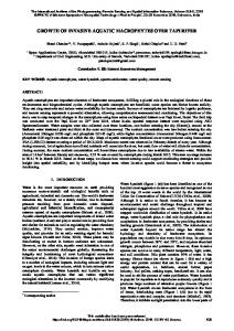
4. GRABCUT ALGORITHM Our implementation of GrabCut is as follows (Figure 1):
Situation Usually
Method The average value of multi-band
Formula 𝑛
𝑝=
1 ∑ 𝑏𝑎𝑛𝑑(𝑘) 𝑛
Draw a Rectangle
𝑘=1
RGB Image
Vegetation extraction (with NIR) Water area extraction (with NIR)
RGB image to gray image NDVI (Normalized Difference Vegetation Index) NDWI (Normalized Difference Water Index)
𝐺𝑟𝑎𝑦 = 𝑅 ∗ 0.299 +𝐺 ∗ 0.587 +𝐵 ∗ 0.114 𝑁𝐼𝑅 − 𝑅 𝑁𝐷𝑉𝐼 = 𝑁𝐼𝑅 + 𝑅 𝑁𝐷𝑊𝐼 =
Initialization Initialize GMMs
Learning GMM components
𝐺 − 𝑁𝐼𝑅 𝐺 + 𝑁𝐼𝑅
Assign GMMs Components
Learn GMMs
Table 1. Transform a multi-band image to a single band image
User Editing
Construct Graph Graph Cut
3.2 Graph building
Estimate Segmentation
Then the image goes through a Sobel filter so that edge features can be extracted. From the filtered image a graph is built by considering each pixel in the image as a node. Each node connects to its eight neighbours by edges. Each edge has a weight relating to the image local cost. Letting 𝑓𝐺 (𝑝, 𝑞) represents the local cost on the directed link from pixel p to a neighbouring pixel q, the local cost function is: 𝑓𝐺 (𝑝, 𝑞) = (1 −
𝐺(𝑞)−min(𝐺) max(𝐺)−min(𝐺)
)∙
1 𝑑𝑖𝑠𝑡𝑎𝑛𝑐𝑒(𝑝,𝑞)
(1)
No
Satisfied? Yes Final result
Figure 1. Our implementation of GrabCut 4.1 Initialization
where 𝐺 is the gradient magnitude. Considering an image 𝑇, the horizontal and vertical derivative approximations 𝐺𝑥 and 𝐺𝑦 are defined respectively as the following convolutions with 𝑇: −1 𝐺𝑥 = [−2 −1
0 +1 +1 0 +2] ∗ 𝑇 𝑎𝑛𝑑 𝐺𝑦 = [ 0 0 +1 −1
+2 +1 0 0 ] ∗ 𝑇 (2) −2 −1
The following expressions are used to obtain the gradient magnitude: 𝐺 = √𝐺𝑥2 + 𝐺𝑦2
(3)
The paper (Rother et al. 2004) introduced an incomplete trimaps to increasing versatility of user interaction. In our implementation, each pixel would be marked as foreground, background, the most probably foreground or the most probably background. User draws a rectangle around the object to be segmented, the pixels inside the ractangle are marked as the most probably foreground and the outside is background. Both the foreground GMM and the background GMM are taken to be a full-covariance Gaussian mixture with k components (typically k = 5). The foreground GMM is initialized with the pixel marked as foreground or the most probably foreground, and the background GMM is initialized with the pixel marked as background or the most probably background. Then the two models are initialized by k-means algorithm.
3.3 Algorithm flow 4.2 Learning GMM components The algorithm would work as follows: (1) The user clicks on the seed point somewhere along the desired image boundary. (2) A graph would be built by the pixels in the square area, which takes the seed point as square centre, in the image. Empirically, the width of the square is 500 pixels. (3) Dijkstra’s algorithm is used to find a minimum cost path from the seed point to every other pixel in the image. (4) As the mouse moves, the minimum cost path from the cursor position back to the last seed point is displayed. (5) The user clicks on the image boundary again to place another seed point, and the minimum cost path back to the last seed point is added to the boundary. (6) Repeated steps (2) to (5) until the path reaches the goal point or the start point.
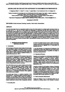
Each pixel marked as foreground or the most probably foreground is assigned to the most likely Gaussian component in the foreground GMM. Similarly, pixel marked as background or the most probably background is assigned to the most likely background Gaussian component. The new GMM parameters are learned from the pixel sets created in the previous step. 4.3 Graph cut The algorithm is computationally efficient, and it gives a globally optimal solution to the binary segmentation problem. In the approach, all pixels are connected by t-links to the additional two terminal nodes, called source and sink, respectively, as depicted in Figure 2.
This contribution has been peer-reviewed. https://doi.org/10.5194/isprs-archives-XLII-2-W7-961-2017 | © Authors 2017. CC BY 4.0 License.
962
The International Archives of the Photogrammetry, Remote Sensing and Spatial Information Sciences, Volume XLII-2/W7, 2017 ISPRS Geospatial Week 2017, 18–22 September 2017, Wuhan, China
4.4 User editing The user can specific some pixel to foreground, background, the most probably foreground or the most probably background by different mouse actions. Then we would restart the iterative process until we get a satisfied result. 5. EXPERIMENTAL RESULTS
Figure 2. A graph with two terminal nodes The weights of these edges are computed as the equations (see Table 2), so that pixels are more compatible with foreground or background region get stronger connections to the respective source or sink. The n-links between adjacent pixels are assigned weights 𝜔(𝑚, 𝑛). Point label Foreground
Terminal Source Sink Source Sink Source
Background
weight λ 0 0 λ − ln( 𝑝(𝑚|ℱ))
The most probably foreground & the most probably Sink − ln( 𝑝(𝑚|ℬ)) background Table 2. The weights of t-links
where − ln( 𝑝(𝑚|ℱ)) and − ln( 𝑝(𝑚|ℬ)) are the likelihood that the pixel belongs to the foreground and background respectively. λ is a large constant value calculated as follows to ensure that it is the largest weight in the graph: 𝛽 = (2 ∗ 𝑎𝑣𝑒𝑟𝑎𝑔𝑒(||𝑧𝑚 − 𝑧𝑛 ||2 )−1 𝜔(𝑚, 𝑛) =
𝛾 𝑑𝑖𝑠𝑡𝑎𝑛𝑐𝑒(𝑚,𝑛)
λ = max(𝜔(𝑚, 𝑛))
exp(−𝛽||𝑧𝑚 − 𝑧𝑛 ||2 )
(4) (5) (6)
where 𝑧𝑚 is the colour of pixel m. 𝛾 is a constant number. Empirically, we used 𝛾 = 50. A min-cut/max-flow algorithm (Boykov, 2004) on the graph with two terminal nodes is a portioning of the nodes in the graph into disjoint subsets 𝒮 (source) and 𝒯 (sink) , such that the node in 𝒮 is foreground and the node in 𝒯 is background.
(a) First seed point
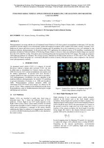
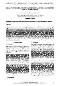
In order to test the applicability and stability of the methods, we study and analyse two basic types of features, including water area and vegetation. Figure 3-4 presents a water area extraction with our methods. Figure 5-6 presents a vegetation extraction with our methods. All these features are chosen from a WorldView-2 Image which is covering a test area in Hebei, China. In Figure 3 and 5, (a) shows specifying the start point, (b) shows the contour tracing step and placing another seed point, (c) shows placing the last seed point, which is closed to the start point, and (d) is the final result shown as a vector boundary. In Figure 4 and 6, (a) shows the initialization step by drawing a rectangle, (b) shows the first graph cut result and user editing step, (c) shows the last graph cut result, and (d) is the final result shown as a vector boundary. Quantitatively, we made a statistics of the area of vector boundaries and the runtime when comparing our final results with manual results. The computer used in our experiments is configured as Intel 2.40 GHz CPU, 4 GB RAM. Water area Vegetation Manual result 40902 64282 Intelligent scissors 40525 63915 GrabCut 40468 62424 Table 3. The area of vector boundaries Water area Vegetation Manual result 42s 29s Intelligent scissors 20s 16s GrabCut 45s 60s Table 4. The runtime of our experiments As shown in Table 3, compared with the manual result, the methods described in this paper can maintain good feature boundaries, and the accuracy can reach more than 95%. As shown in Table 4, the method based on intelligent scissors is much faster than the manual processing, but the method based on GrabCut is slower than the manual processing due to the graph cut step, which runs in time nearly linear in the number of graph nodes.
(b) Middle seed point (c) Last seed point Figure 3. Water area extraction with intelligent scissors
(d) Final result
This contribution has been peer-reviewed. https://doi.org/10.5194/isprs-archives-XLII-2-W7-961-2017 | © Authors 2017. CC BY 4.0 License.
963
The International Archives of the Photogrammetry, Remote Sensing and Spatial Information Sciences, Volume XLII-2/W7, 2017 ISPRS Geospatial Week 2017, 18–22 September 2017, Wuhan, China
(a) Initialization
(b) User editing (c) Graph cut Figure 4. Water area extraction with GrabCut
(a) First seed point
(b) Middle seed point (c) Last seed point Figure 5. Vegetation extraction with intelligent scissors
(b) User editing (c) Graph cut Figure 6. Vegetation extraction with GrabCut
(a) Initialization
6. CONCLUSIONS AND FUTURE WORK The paper has described two interactive segmentation methods for solving the problem of object extraction in remote sensing images. The first is based on intelligent scissors, while the other is based on GrabCut. The experimental results obtained on two different geographical categories in remote sensing images have shown that the proposed approach is easy to implement and effective in obtaining accurate boundaries. Future work may include reducing the delay due to the graph build step in intelligent scissors and the graph cut step in GrabCut. ACKNOWLEDGEMENTS This research was funded by: (1) the National Natural Science Foundation for Young Scientists of China (Project Nos. 41471299); (2) Central Public-interest Scientific Institution Basal Research Funds (Project Nos. 777161101 and 777161102). The interactive segmentation tools are integrated in the software FeatureStation, which is developed by the Chinese Academy of Surveying and Mapping.
(d) Final result
(d)Final result
(d) Final result
Boykov, Y., Kolmogorov, V., 2004. An experimental comparison of min-cut/max-flow algorithms for energy minimization in vision. IEEE Transactions on Pattern Analysis & Machine Intelligence, 26(9), pp. 1124-1137. Boykov, Y., Funka-Lea, G., 2006. Graph cuts and efficient n-d image segmentation. International Journal of Computer Vision, 70(2), pp. 109-131. Li, Y., et al. 2004. Lazy snapping. Acm Transactions on Graphics, 23(3), pp. 303-308. Mortensen, E. N., Barrett, W. A., 1995. Intelligent scissors for image composition. Conference on Computer Graphics and Interactive Techniques, pp.191-198. Kass, M. et al. 1987. Snakes: Active contour models. International Journal of Computer Vision, pp. 321-331. Rother, C., et al. 2004. "GrabCut": interactive foreground extraction using iterated graph cuts. ACM SIGGRAPH, Vol.23, pp. 309-314.
REFERENCES Boykov, Y., Jolly, M. P., 2001. Interactive graph cuts for optimal boundary & region segmentation of objects in N-D images. ICCV, Proceedings. Eighth IEEE International Conference on IEEE, vol.1, pp. 105-112.
This contribution has been peer-reviewed. https://doi.org/10.5194/isprs-archives-XLII-2-W7-961-2017 | © Authors 2017. CC BY 4.0 License.
964