Hindawi Publishing Corporation Mathematical Problems in Engineering Volume 2015, Article ID 120954, 6 pages http://dx.doi.org/10.1155/2015/120954
Research Article Research on Signal Processing of MEMS Gyro Array Xunsheng Ji Key Laboratory of Education Ministry of Light Industry Advanced Process Control, Jiangnan University, Wuxi 214122, China Correspondence should be addressed to Xunsheng Ji;
[email protected] Received 18 April 2015; Revised 11 June 2015; Accepted 14 June 2015 Academic Editor: Dapeng P. Du Copyright © 2015 Xunsheng Ji. This is an open access article distributed under the Creative Commons Attribution License, which permits unrestricted use, distribution, and reproduction in any medium, provided the original work is properly cited. A new random drift model and the measured angular rate model of MEMS gyro are presented. Based on such models, signal processing techniques are used to decrease gyro drift. Kalman filtering equations have been built for static measurement and dynamic measurement of the gyro array, which combines 𝑁 individual gyros into a single rate estimate. By selecting the favorable cross correlation coefficient between individual gyros in the noise correlation matrix, the gyro array performance can be significantly improved over that of any individual component device. A new gyro array dynamic measurement procession is also presented. Data fusion of the difference between individual gyro dynamic measurements can identify every gyro real-time drift out and get its noisy test. Based on the laws of the gyro curve motion, the tested dynamic signal is filtered to improve the gyro accuracy. All these processings have been implemented by digital signal processor. Simulation results show that the static drift can decrease from 22.1∘ /h to 0.184∘ /h and the dynamic drift can decrease from 22.1∘ /h to 8.98∘ /h.
1. Introduction Recently, the development of microelectromechanical system (MEMS) technologies [1–3] enables us to have a MEMS gyro small enough, which has a great potential to be applied to many applications such as virtual reality, car navigation, inertial navigation for small air vehicles, and space avionics. Moreover, for conventional gyros, such as mechanical or optical gyros, they have other good properties including (1) compact size, (2) small weight, (3) low power consumption, (4) low cost micromachining process, and (5) ease of mass production [4, 5]. These factors offer a wide range of applications for MEMS gyros, ranging from stability and navigation control in spacecraft to rollover detection for automotive applications, consumer electronics, robotics, and a variety of military applications. Compared to mechanical or optical gyros, MEMS gyro present performance is not high enough to substitute them. So it is necessary to improve the performance of MEMS gyros to extend their utilities. Gyro drift is the main factor that affects its performance. Therefore, how to eliminate the gyro drift effectively is the essential problem to guarantee the gyro accuracy. In general, the gyro drift is classified into systematic and random drift.
By use of proper mathematical model and drift compensation calculation, the effect of systematic drift on accuracy can be eliminated. However, random drift is weak. And it is a slow time-varying signal. It is often affected by some indeterminate factors such as exterior environment noise. Simple methods to compensate the random drift are not effective. The random drift error includes the drift instability, rate random walk (RRW), and angular random walk (ARW). Theoretically, the drift instability and the measured true rate can be modeled as random walk process, driven by the white noise. In the area of MEMS gyro, significant accuracy improvements in the designing and manufacturing process will require increased costs and are time-consuming. Thus, signal processing techniques applied to multiple sensor configurations are being examined and are expected to improve the accuracy of existing MEMS gyro. Appropriate processing of microsensor outputs appears to be the quickest and the most feasible method of improving sensor accuracy. Up to present, there appear many approaches proposed for signal processing techniques of the gyro drift data. Sensor modeling and the active control of the sensor dynamics for model identification and angular rate sensing were focused on to compensate the gyro drift [2, 6–10]. ARMA time series autoregression
2
Mathematical Problems in Engineering
model of the gyro original drift or its first-order difference was proposed to decrease the noise and predict the gyro measurement [11–17]. Neural network structure with the name of RBF [18, 19] and GRBF [20, 21] was applied to reduce drift influence on the gyro accuracy. The waveletbased denoising was employed to reconstruct outputs of the MEMS gyro and to increase the gyro accuracy [22–24]. All these processing techniques were based on single MEMS gyro output and often aimed at its static measurement, so the performance improvement of the gyro dynamic measurement was limited. In this paper, a signal processing technique for a MEMS gyro array, combining 𝑁 individual gyros into a single rate estimation [4, 5], is brought up to improve gyro accuracy. A new random drift model of gyro is presented firstly. The true angular rate is also modeled as a random walk driven by white noise. Based on these models, Kalman filtering equations are built to process gyro array static measurement and dynamic measurement. By setting favorable cross coefficients between individual gyros of the noise correlation matrix, the optimal procession result will be gotten from the gyro array static measurement. To the gyro array dynamics measurement, difference between individual gyros outputs can be served as a new variable and Kalman filtering equations will be built in order to get every gyro real-time drift and its noisy measurement indirectly. Based on the laws on the dynamic motion, the further Kalman filtering procession of the gyro noisy measurement can decrease noise of the detrained dynamic measurement and improve its signal-to-noise rate (SNR) evidently. The remainder of this paper is organized as follows. In Section 2, we present a new gyro random drift model of the single gyro and then get the Kalman filtering equations for the gyro array static measurement. New Kalman filtering equations for gyro array dynamic measurement have also been built to identify the individual gyro real-time drift and the measured true rate in this section. Subsequently, in order to decrease noise of the identified true rate, the filtering equation is also given out. All simulation examples together with performance comparison of different Kalman filters are contained in Section 3. Section 4 presents discussion, conclusions, and future research issues.
2. Signal Processing Techniques of MEMS Gyro Array Drift 2.1. Signal Processing Technique of Static Drift. The gyro noisy measurement 𝑥 of the true angular rate 𝜔 can be described as 𝑥 = 𝜔 + 𝑏 + 𝑛,
(1)
where 𝑏 is equal to slowly variant random quantity, which is denoted as the gyro drift, and 𝑛 is white noise process denoted as ARW noise. Mathematically, the gyro drift can be modeled as a random walk, driven by term 𝑤𝑏 , denoted as RRW noise [4, 5]. Consider 𝑏̇ = 𝑤𝑏 ,
(2)
where 𝑤𝑏 is delta-correlated process with correlation function 𝑞𝑏 ; that is, 𝐸 [𝑤𝑏 ] = 0, 𝐸 [𝑤𝑏 (𝑡) 𝑤𝑏 (𝑡 + 𝜏)] = 𝑞𝑏 ⋅ 𝛿 (𝜏) .
(3)
The true rate 𝜔 can be modeled as a random walk driven by a noise with intensity 𝑞𝜔 ; that is, [4, 5, 25, 26] 𝜔̇ = 𝑤𝜔 , 𝐸 [𝑤𝑤 ] = 0,
(4)
𝐸 [𝑤𝜔 (𝑡) 𝑤𝑤 (𝑡 + 𝜏)] = 𝑞𝑤 ⋅ 𝛿 (𝜏) . One of the main virtues of the silicon micromachined gyro is its easy mass production. Gyro array measurement can be used to increase the gyro accuracy. With the above statistical description, the gyro array measure equation can be written in the vector form as 𝑦𝑖 = 𝑏𝑖 + 𝜔 + V𝑖 ,
(5)
where 𝑦𝑖 is measure result of every gyro and 𝑏𝑖 is its drift and V𝑖 is its measuring noise and is a continuous-time 𝛿 correlative process. The measuring noise vector correlation matrix 𝑅 is as follows: 𝐸 [V (𝑡)] = 0, 𝐸 [V (𝑡) V𝑇 (𝑡 + 𝜏)] = 𝑅 ⋅ 𝛿 (𝜏) ,
(6)
where V = [V1 V2 ⋅ ⋅ ⋅ V𝑁]. When correlation matrix 𝑅 ∈ 𝑅𝑁×𝑁 is a non-diagonal matrix, ARW noise among every gyro is correlated with each other. Correlation scale function 𝑞𝑏 from every 𝜔𝑏 is the correlation, that is, 𝐸 [𝑤𝑏 ] = 0, 𝐸 [𝑤𝑏 (𝑡) 𝑤𝑏 (𝑡 + 𝜏)] = 𝑄𝑏 ⋅ 𝛿 (𝜏) ,
(7)
where the matrix 𝑄𝑏 ∈ 𝑅𝑁×𝑁 is nondiagonal matrix; the RRW noises among every gyro are correlated with each other. Based on measured model, the following discrete Kalman filtering equations can be gotten by (8). Consider 𝑋𝑘 = Φ𝑘/𝑘−1 𝑋𝑘−1 + Γ𝑘−1 𝑊𝐾−1 , 𝑌𝑘 = 𝐻𝑘 𝑋𝑘 + 𝑉𝑘 ,
(8)
Φ𝑘/𝑘−1 = 𝐼𝑁×𝑁, Γ𝑘−1 = 𝑇 ∗ 𝐼𝑁×𝑁, . 𝐻𝑘 = [𝐼 .. 1] ∈ 𝑅𝑁×(𝑁+1) ,
(9)
Mathematical Problems in Engineering
3
where 𝑇 = sampling internal of the measured signal; 𝑊𝑘 = system white noise series; 𝑉𝑘 = measurement noise series. Consider 1 0 ⋅⋅⋅ 0 1 [0 1 ⋅ ⋅ ⋅ 0 1] [ ] . [ ] [𝐼 .. 1] = [ . . ] . [. . ] . .] [. . d
𝑦2 (𝑘) = 𝑏3 − 𝑏2 + 𝑛3 − 𝑛2 , 𝑦3 (𝑘) = 𝑏3 − 𝑏1 + 𝑛3 − 𝑛1
.
(10)
[0 0 ⋅ ⋅ ⋅ 1 1]𝑁×(𝑁+1)
(14)
𝑛𝑏2 − 𝑛𝑏1 −1 1 0 [𝑛 − 𝑛 ] [ 0 −1 1] =[ ] × 𝑋 + [ 𝑏3 𝑏2 ] . [−1 0 1]
They have the following property:
[𝑛𝑏3 − 𝑛𝑏1 ]
All parameters of the filter are described as Φ = 𝐼3 ,
𝐸 [𝑊𝑘 ] = 0, Cov [𝑊𝑘 , 𝑊𝑗 ] = 𝐸 [𝑊 (𝑡) 𝑊𝑇 (𝜏)] = 𝑄𝑘 𝛿𝑘𝑗 =
Γ = 𝐼3 ,
𝑞 , 𝑇
(15)
𝑊 = [𝑛𝑏1 , 𝑛𝑏2 , 𝑛𝑏3 ] ,
𝐸 [𝑉𝑘 ] = 0,
𝑟 Cov [𝑉𝑘 , 𝑉𝑗 ] = 𝐸 [𝑉 (𝑡) 𝑉𝑇 (𝜏)] = 𝑅𝑘 𝛿𝑘𝑗 = , 𝑇
𝑉 = [𝑛𝑏2 − 𝑛𝑏1 , 𝑛𝑏3 − 𝑛𝑏2 , 𝑛𝑏3 − 𝑛𝑏1 ] . (11)
Cov [𝑊 (𝑡) , 𝑉 (𝜏)] = 𝐸 [𝑊 (𝑡) 𝑉 (𝜏)] = 0, 𝑄𝑘 = [
Measurement equation is as follows: 𝑦1 (𝑘) = 𝑏2 − 𝑏1 + 𝑛2 − 𝑛1 ,
𝑄𝑏 (𝑘)
0
0
𝑄𝜔 (𝑘)
],
𝑅𝑘 = [𝑄𝑎 (𝑘)] , where 𝑄𝑎 is covariance of the ARW noise and 𝑄𝜔 (𝑘) denotes noise intensity of a random walk, which is modeled as the true rate. 2.2. Signal Processing Technique of Dynamic Drift 2.2.1. Real-Time Identification of the Random Drift from the Dynamic Measurement. When the gyro is used to measure dynamics signal, the true rate 𝜔 cannot be gotten by the output of the Kalman filtering of (8). As seen from (1), 𝜔 is the measurement of the true rate and is similar to every gyro measurement. Difference between the two individual gyros measurements will become as 𝑥𝑖 (𝑡) − 𝑥𝑗 (𝑡) = 𝑏𝑖 − 𝑏𝑗 + 𝑛𝑖 − 𝑛𝑗 .
(12)
Difference between the two gyros measurements is equal to the difference between their drifts. When 𝑥𝑖 (𝑡) and 𝑏𝑖 + 𝑛𝑖 are, respectively, adopted as state variables of Kalman filter, Kalman filter state equation will become the same. Thus, real-time gyro drift can be identified and the true angular rate 𝜔 is the 𝐷 value between the individual gyro original measurement 𝑥𝑖 and its detrained drift 𝑏𝑖 + 𝑛𝑖 . For the 𝑁 = 3 gyro array dynamic measurement, Kalman filtering equations will be as state equation as follows:
𝑥3 (𝑘 + 1) = 𝜔 + 𝑏3 + 𝑛𝑏3 .
Further Kalman filtering can reduce the noise of the noisy tested out 𝜔. The gyro rotation is curve motion. When the angle 𝜑𝑘 , angular rate 𝜔𝑘 , and rate acceleration 𝛼𝑘 are the state variables of the Kalman filter, the state equations are as follows: 𝛼 𝑇2 𝜑𝑘 = 𝜑𝑘−1 + 𝜔𝑘−1 𝑇 + 𝑘−1 , 2 (17) 𝜔𝑘 = 𝜔𝑘−1 + 𝛼𝑘−1 𝑇, 𝑎𝑘 = 𝑎𝑘−1 + 𝑗𝑘−1 𝑇. 𝑗𝑘 = first-order derivative of 𝛼𝑘 and is often regarded as the white noise. When 𝑋 = [𝜑𝑘 , 𝜔𝑘 , 𝛼𝑘 ], the tested out 𝜔𝑘 can be denoised by following Kalman filtering equations. State equation is as follows: 𝑋𝑘 = Φ𝑘/𝑘−1 𝑋𝑘−1 + Γ𝑘−1 𝑗𝑘−1 .
(18)
Measurement equations are as follows: ̂𝑘 = 𝜔𝑘 + V𝑘 = 𝐻𝑘 𝑋𝑘 + V𝑘 , 𝜔 𝑇2 [1 𝑇 ] 2] [ Φ = [0 1 𝑇 ] , [ ] 0 0 1 [ ]
(19)
0
[ ] Γ = [0] , [𝑇]
𝑥1 (𝑘 + 1) = 𝜔 + 𝑏1 + 𝑛𝑏1 , 𝑥2 (𝑘 + 1) = 𝜔 + 𝑏2 + 𝑛𝑏2 ,
In this Kalman filtering equation, input variables are not the individual gyros direct measurement but are their difference. The output variables are not 𝜔 but 𝑏𝑖 +𝑛𝑖 . The noisy 𝜔 is as follows: 𝜔𝑖 = 𝑥𝑖 − (𝑏𝑖 + 𝑛𝑖 ) . (16)
(13)
𝐻 = [0 1 0] . Thus, 𝜔𝑘 can be Kalman-filtered to decrease the noise and increase gyro measurement SNR.
Mathematical Problems in Engineering
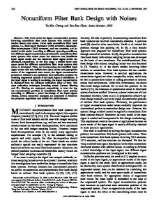
3. Simulation A simulation study, using the preliminary Kalman filtering, is conducted to testify the analytical results. 3.1. Simulation of the Static Drift. Kalman filtering can give out the globally optimal minimum-variance estimate. Correlation among the individual gyros measurements leads to correlation among the RRW noises and among the ARW noises. Noise variance matrix of 𝑄𝑎 and 𝑄𝑏 can be gotten by the Allan variance computation of gyro drift data [27]. By multiplying with 𝑇, unit of 𝑄𝑏 can be changed from deg2 /sec3 to deg2 /sec2 . Variance matrix 𝑄𝜔 of the white noise, driven by the true rate 𝜔, is decided by the rate stability of the tested platform. In this paper, correction coefficients among all the gyros are set as the same constant 𝜌. For 𝑁 = 3 gyro
Times of the bias reducing
4 120 100 80 60 40 20 0 −1
−0.8 −0.6 −0.4 −0.2 0 0.2 0.4 Cross correlation 𝜌
[ 𝑅𝑘 = [ [ [
0
0
var (𝑥1 )
0
0
var (𝑥2 )
0
0
0.8
1
Figure 1: Relation between cross correlation 𝜌 and the times of the gyro drift reduction.
array, covariance matrices 𝑄𝑘 and 𝑅𝑘 will be computed by the following equations:
𝜌√var (𝑥1 ) var (𝑥2 ) 𝜌√var (𝑥1 ) var (𝑥3 ) var (𝑥1 ) [ [ [𝜌√var (𝑥 ) var (𝑥 ) var (𝑥2 ) 𝜌√var (𝑥2 ) var (𝑥3 ) [ 1 2 𝑄𝑘 = [ [ [𝜌√var (𝑥 ) var (𝑥 ) 𝜌√var (𝑥 ) var (𝑥 ) var (𝑥3 ) 1 3 2 3 [ [
0.6
0
0 0 0
] ] ] ] ], ] ] ]
0.0001 ∗ var (𝑥)]
(20)
0
] ], ] var (𝑥3 )] 0
where 𝑥 = (𝑥1 + 𝑥2 + 𝑥3 )/3 is mean of the gyro array measurement. Var(𝑥) is the variance of the signal 𝑥. Data of the simulation are from our self-exploited micromachined gyro measurement. Every individual gyro drift of the gyro array is 22.1∘ /h and the scale factor is 4.3759 mv/∘ /sec. The initial filtering value 𝑋0 is set as [0 0 0 0]𝑇 . The same correlation coefficient 𝜌 is set with −1 ⩽ 𝜌 ⩽ 1 and its 0.05 interval during the filtering. Relations between the times of the zero-drift stability increase and the 𝜌 variation is shown in Figure 1. As seen from Figure 1, variation of 𝜌 affects the variation of gyro drift greatly. When 𝜌 = 0.5, the filtering result is the most optimal. The drift error decreases from 22.1∘ /h to 0.184∘ /h. When 𝜌 = 0.5, every gyro drift and gyro array overall drift are shown in Figure 2. Thus, when gyros are correlated and correlation coefficient 𝜌 is selected favorably, gyro array drift will be reduced greatly. 3.2. Simulation of the Dynamic Measurement. Gyro performance of the dynamic measurement simulation is the same as that of the static simulation. The detrained drift of one gyro from the gyro array and its original drift are compared in Figure 3.
The sinusoid, whose amplitude is 0.5 V and its frequency is 120 Hz, is added to the 𝐷 value between original drift and detached gyro drift as the true noisy gyro dynamic signal 𝜔. The filtered result is compared with the unprocessed dynamic signal shown in Figure 4. Finally, the drift reduces from 22.1∘ /h to 8.89∘ /h. It shows the effectiveness of such Kalman filtering of the dynamic measurement. The simulation also shows that the accuracy improvement of the gyro dynamic measurement nearly has no relation to the correlation coefficient 𝜌. The real-time of the Kalman filtering has been verified on the digital signal processor TMS320C67X.
4. Discussion and Conclusion A random drift model and the measured true rate model of single gyro are presented. Gyro array is used to increase gyro performance. Different Kalman filtering equations are built for the gyro static measurement, dynamic measurement, and the tested out noisy rate would be further processed. Setting the favorable correlation coefficient 𝜌, the gyro static drift can decrease from 22.1∘ /h to 0.184∘ /h. As sinusoid is used as the dynamics signal, the gyro dynamics drift decreases from 22.1∘ /h to 8.89∘ /h and the performance improvement nearly has no relation to the correlation coefficient 𝜌. The db4
5
×10−3 1
0.5 0 −0.5 −1
0
0.5
1
1.5
2
2.5
3
Signal number
3.5 ×10⁴
Signal magnitude (V)
Signal magnitude (V)
Mathematical Problems in Engineering
(a) Component gyros drift for 𝑁 = 3 correlated gyros simulation
×10−5 1.5 1 0.5 0 −0.5 −1 −1.5 0
0.5
1
1.5 2 Signal number
2.5
3
3.5 ×10⁴
(b) Kalman filtering result for 𝑁 = 3 correlated gyros simulation
0.0664 0.0662 0.066 0.0658 0.0656 0.0654 0.0652 0.065
0
0.5
1
1.5 2 Signal number
2.5
3
3.5 ×10⁴
Signal magnitude (V)
Signal magnitude (V)
Figure 2: 𝑁 = 3, 𝜌 = 0.5 correlated gyros simulation. 0.0664 0.0662 0.066 0.0658 0.0656 0.0654 0.0652 0.065
0
0.5
(a) Original gyro drift
1
1.5 2 Signal number
2.5
3
3.5 ×10⁴
(b) Tested out gyro bias
0.6 0.4 0.2 0 −0.2 −0.4 −0.6 −0.8
0
50
100
150 200 250 300 Numbers of signal
350
400
450
(a) Original noisy tested out dynamic rate
Signal magnitude (V)
Signal magnitude (V)
Figure 3: Dynamic measure simulation. 0.6 0.4 0.2 0 −0.2 −0.4 −0.6 −0.8
0
50
100
150 200 250 300 Numbers of signal
350
400
450
(b) Kalman-filtered noisy dynamic rate
Figure 4: Simulation of the further Kalman filtering of the noisy tested out dynamic rate.
wavelet is used as wavelet basis; the 6-level wavelet transformation (WT) denoising of gyro array measurement can make its static drift decrease from 22.1∘ /h to 5.1∘ /h and can make the dynamic drift decrease from 22.1∘ /h to 15.1∘ /h. Processing time of every signal is 0.13 ms. So the new approach in this paper is effective and will have its further application. In this paper, single gyros are made up of individual gyro and all data are also from every individual gyro measurement. The actual degree of performance improvement remains to be determined by experimental validation after the actual gyro array is manufactured. True noise model is not white noise but will be further ascertained. More emphases will be put on the establishment of accurate gyro array dynamic measurement model.
Conflict of Interests The author declares that there is no conflict of interests regarding the publication of this paper.
References [1] H. Yanling, L. Bo, and Z. Guangtao, “Design of a MEMS gyroscope array with high sensitivity,” Huazhong University of Science & Technology (Natural Science Edition), vol. 42, no. 3, pp. 42–47, 2014. [2] R. T. M’Closkey, S. Gibson, and J. Hui, “Modal parameter identification of a MEMS gyroscope,” in Proceedings of the American Control Conference, pp. 1699–1704, Chicago, Ill, USA, June 2000. [3] Y.-Q. Zhang and S.-R. Wang, “Research on closed-loop driving technology for silicon micro-gyroscope array,” Measurement Control Technology, vol. 33, no. 3, pp. 64–67, 2014. [4] W. Wang, X. Lv, and F. Sun, “Design of a novel MEMS gyroscope array,” Sensors, vol. 13, no. 2, pp. 1651–1663, 2013. [5] D. S. Bayard, “High accuracy inertial sensors from inexpensive components,” NASA JPL New Technology Report NPO, NASA, 2003. [6] S. B. David and R. P. Scott, “Combining multiple gyro outputs for increased accuracy,” NASA JPL New Technology Report NPO, 2003.
6 [7] R. P. Leland, “Adaptive mode tuning for vibrational gyroscopes,” IEEE Transactions on Control Systems Technology, vol. 11, no. 2, pp. 242–247, 2003. [8] X. He, M. Wu, and X. Hu, “Research on closed-loop driving technology for silicon micro-gyroscope array,” Measurement Control Technology, vol. 33, no. 3, pp. 64–67, 2014. [9] S. Park and R. Horowitz, “Adaptive control for the conventional mode of operation of MEMS gyroscopes,” Journal of Microelectromechanical Systems, vol. 12, no. 1, pp. 101–108, 2003. [10] A. Shkel, R. T. Howe, and R. Horowitz, “Modeling and simulation of micromachined gyros in the presence of imperfections,” in Proceedings of the International Conference on Modeling and Simulation of Microsystems, pp. 605–608, April 1999. [11] A. M. Shkel, R. Horowitz, A. A. Seshia, S. Park, and R. T. Howe, “Dynamics and control of micromachined gyroscopes,” in Proceedings of the American Control Conference (ACC ’99), vol. 3, pp. 2119–2124, IEEE, San Diego, Calif, USA, June 1999. [12] S. Baglio, N. Savalli, and S. Castorina, “Theoretical study, modeling and realization of resonant gyroscopes with optical output,” in Proceedings of the IEEE Sensors, vol. 2, pp. 1069–1074, IEEE, Orlando, Fla, USA, June 2002. [13] L.-J. Miao, F.-S. Zhang, J. Shen, and W. Liu, “Data analysis and modeling of fiber optic gyroscope drift,” Journal of Beijing Institute of Technology (English Edition), vol. 11, no. 1, pp. 50–55, 2002. [14] A. Duslman, “On gyro drift models and their evaluation,” IEEE Transactions on Aerospace and Navigation Electronic, vol. 5, no. 2, pp. 230–234, 2002. [15] S. M. Seong, J. Lee Gyu, and C. G. Park, “Equivalent ARMA model representation for RLG random errors,” IEEE Transactions on Aerospace and Electronic Systems, vol. 36, no. 1, pp. 286– 290, 2000. [16] H. Pan, B. Yang, and L. Wang, “Measurement of random gyro drift and establishment of mathematical model,” Aerospace Shanghai, vol. 20, no. 3, pp. 20–23, 2003. [17] R. Peesapati, S. L. Sabat, K. Kumar Anumandla, P. Karthik Kandyala, and J. Nayak, “Design and implementation of a realtime co-processor for denoising fiber optic gyroscope signal,” Digital Signal Processing, vol. 23, no. 5, pp. 1813–1825, 2013. [18] W. Hao and W. Tian, “Modeling the random drift of micromachined gyroscope with neural network,” Neural Processing Letters, vol. 22, no. 3, pp. 235–247, 2005. [19] R. Zhu, Y. Zhang, and Q. Bao, “A novel intelligent strategy for improving measurement precision of FOG,” IEEE Transactions on Instrumentation and Measurement, vol. 49, no. 6, pp. 1183– 1188, 2000. [20] L. Xue, C.-Y. Jiang, H.-L. Chang, Y. Yang, W. Qin, and W.-Z. Yuan, “A novel Kalman filter for combining outputs of MEMS gyroscope array,” Measurement, vol. 45, no. 4, pp. 745–754, 2012. [21] C. Jiang, L. Xue, H. Chang, G. Yuan, and W. Yuan, “Signal processing of MEMS gyroscope arrays to improve accuracy using a 1st order markov for rate signal modeling,” Sensors, vol. 12, no. 2, pp. 1720–1737, 2012. [22] R. Yuan, X. Wei, Z. Li et al., “De-noising algorithm for signal in FOG based on wavelet filtering using threshold value,” Journal of Chinese Inertial Technology, vol. 10, no. 5, pp. 43–47, 2014. [23] L.-J. Miao, “Application of wavelet analysis in the signal processing of the fiber optic gyro,” Journal of Astronautics, vol. 21, no. 1, pp. 42–46, 2014. [24] C.-B. Zhang and Z.-L. Deng, “A study on initial alignment technique for strapdown inertial navigation system based on wavelet analysis,” High Technology Letters, vol. 5, pp. 87–89, 2012.
Mathematical Problems in Engineering [25] Q. M. Lam, T. Wilson Jr., R. Contillo, and D. Buck, “Enhancing MEMS sensors accuracy via random noise characterization and calibration,” in Sensors, and Command, Control, Communications, and Intelligence (C3I) Technologies for Homeland Security and Homeland Defense III, vol. 5403 of Proceedings of SPIE, September 2004. [26] Q. M. Lam and N. Stamatakos, “Gyro modeling and estimation of its random noise sources,” AIAA 2003-5562, The American Institute of Aeronautics and Astronautics, 2003. [27] H. Hou and N. El-Sheimy, “Inertial sensors errors modeling using allan variance,” in Proceedings of the 16th International Technical Meeting of the Satellite Division of the Institute of Navigation (ION GPS/GNSS ’03), pp. 2860–2867, Portland, Ore, USA, September 2003.
Advances in
Operations Research Hindawi Publishing Corporation http://www.hindawi.com
Volume 2014
Advances in
Decision Sciences Hindawi Publishing Corporation http://www.hindawi.com
Volume 2014
Journal of
Applied Mathematics
Algebra
Hindawi Publishing Corporation http://www.hindawi.com
Hindawi Publishing Corporation http://www.hindawi.com
Volume 2014
Journal of
Probability and Statistics Volume 2014
The Scientific World Journal Hindawi Publishing Corporation http://www.hindawi.com
Hindawi Publishing Corporation http://www.hindawi.com
Volume 2014
International Journal of
Differential Equations Hindawi Publishing Corporation http://www.hindawi.com
Volume 2014
Volume 2014
Submit your manuscripts at http://www.hindawi.com International Journal of
Advances in
Combinatorics Hindawi Publishing Corporation http://www.hindawi.com
Mathematical Physics Hindawi Publishing Corporation http://www.hindawi.com
Volume 2014
Journal of
Complex Analysis Hindawi Publishing Corporation http://www.hindawi.com
Volume 2014
International Journal of Mathematics and Mathematical Sciences
Mathematical Problems in Engineering
Journal of
Mathematics Hindawi Publishing Corporation http://www.hindawi.com
Volume 2014
Hindawi Publishing Corporation http://www.hindawi.com
Volume 2014
Volume 2014
Hindawi Publishing Corporation http://www.hindawi.com
Volume 2014
Discrete Mathematics
Journal of
Volume 2014
Hindawi Publishing Corporation http://www.hindawi.com
Discrete Dynamics in Nature and Society
Journal of
Function Spaces Hindawi Publishing Corporation http://www.hindawi.com
Abstract and Applied Analysis
Volume 2014
Hindawi Publishing Corporation http://www.hindawi.com
Volume 2014
Hindawi Publishing Corporation http://www.hindawi.com
Volume 2014
International Journal of
Journal of
Stochastic Analysis
Optimization
Hindawi Publishing Corporation http://www.hindawi.com
Hindawi Publishing Corporation http://www.hindawi.com
Volume 2014
Volume 2014