Journal of Engineering and Fundamentals Vol. 1(1), pp. 43-47, December, 2014 Available online at http://www.tjef.net ISSN: 2149-0325 http://dx.doi.org/10.17530/jef.14.05.1.1
Research using finite element method of biomechanical behaviours of human femur model under the different loads Kadir Gok* Dumlupinar University, Kutahya Vocational School of Technical Sciences, Turkey
Betul Taspinar Dumlupinar University, School of Health Science, Department of Physiotherapy and Rehabilitation, Turkey
Ferruh Taspinar Dumlupinar University, School of Health Science, Department of Physiotherapy and Rehabilitation, Turkey
Emrah Afsar Dumlupinar University, School of Health Science, Department of Physiotherapy and Rehabilitation, Turkey
Arif Gok Amasya University, Technology Faculty, Department of Mechanical Engineering, Turkey
M. Burak Bilgin Amasya University, Technology Faculty, Department of Mechanical Engineering, Turkey Article history Received: 01.12.2014 Received in revised form: 31.12.2014 Accepted: 31.12.2014 Key words: finite element method, biomechanical behaviour, femur
*
In this study, analysed using finite element method (FEM) of biomechanical behaviours of human femur model under the different loads. Geomagic and Soldiworks program were used for 3D model human of femur model, and Ansysworkbench was used for finite element analysis (FEA). Compression, tension, bending and torsional loading were applied to 3D human femur model. Femur bone was exhibited that the best stabile behavior under the torsional loading. The reason is due to the bone structure. In contrary to this situation, the femur model under the bending loading type has lowest safety factor due to high stress and deformation. Therefore, type of loading on the femur is crucial for surgical procedure and rehabilitation approaches.
Correspondence:
[email protected]
Research using finite element method … K.Gok, B. Taspinar, F.Taspinar, E.Afsar, A. Gok & M.B.Bilgin
1. Introduction Biomechanics, investigates any organism's functions, and behaviors under different conditions interaction with artificial systems such as implants or prostheses, is a science. In today, biomechanics is conducted to parallel as with engineering science, and it is applied to in many parts of the human body. Biomechanics discipline is very important in many processes such as detection and diagnosis, surgical applications, orthotic prosthetic applications, pre and post rehabilitative applications and pre surgical planning. Modeling of biomechanical using the FEA may be useful for validation of experimental or analytical results and considered as a reliable tool to develop of new surgical techniques. Many studies using FEA in literature. Atmaca et al. [1] presented a study was to analyze the loading on the tibial articular cartilage following medial meniscectomy performed in various location and extent in the healthy knee, using FEA on the solid models. Inal et al. [2] conducted to examine and compare the pertrochanteric fixator (PTF) and dynamic hip screw (DHS) using FEA. Arif et al. [3] determined whether there are differences between fatique behaviours of different materials for schanz screws when they are used for intertrochanteric femoral fracture fixation. Atmaca et al. [4] evaluated whether the proximal tibial open wedge osteotomy (PTO) can achieve decreased stress-bearing on the tibia and tarsal bones in addition to correcting the mechanical axis of the lower limb in patients with tibia vara using finite element method. Bessho et al. [5] performed a simulation model that could accurately predict the strength and surface strains of the proximal femur using a CT-based finite
element method. Ota et al. [6] simulated a fracture procedure using FEM and to assess its usefulness. Sowmianarayanan et al. [7] presented the biomechanical behaviour of the femur with three different implant shapes for simple transverse subtrochanteric fracture and the undamaged femur using FEA. Yu et al. [8] investigated the fracture mechanism and stress distributions for proximal femur under the impact forces. Senalp et al. [9] performed the fatigue behavior of stem shapes using FEA. Kayabaşı et al. [10] investigated the static dynamic and fatigue behaviors of the implant. Kayabasi et al. [11] investigated the behavior of newly designed implants load under the body weight. In this study, analysed using FEM the biomechanical behaviours of human femur model under the different loads such as compression, tension, bending and torsional. 2. Computer Aided Modelling and Analysis The human femoral model was scanned using 3D scanner and point cloud was obtained. After that, IGES format was obtained using point cloud data by Geomagic Studio 10 program. 3D model of human femur was created using this IGES format in SolidWorks program as seen in Figure 1. Medullary cavity of 3D human femur model was created using SolidWorks program. The computer aided analyses were performed using AnsysWorkbench software. The 3D CAD models were imported into the AnsysWorkbench software to prepare the FEA. Load, boundary conditions and material models were defined in AnsysWorkbench.
Journal of Engineering and Fundamentals (JEF)
-44-
Journal of Engineering and Fundamentals (JEF), 1(1);43-47, 1 December, 2014
Figure 1. 3D model of human femur model human femur model. A load of 350N was 2.1. Loading and boundary applied in all loading types and the distal conditions Firstly, mesh process was end of the femur was fixed as seen in performed using hex dominant finite Figure 3. The mechanical properties femur element for the FEA as seen in Figure 2. model was given in Table 1. After the The FEA model has 103960 nodes, 33612 loading and the boundary conditions, the elements. The mesh size was chosen as 3 biomechanical properties of the materials mm. Compression, tension, bending and were identified and FEA simulations were torsional loading were applied to 3D solved.
Figure 2. The mesh structure of 3D human femur model
Figure 3. Loading types and boundary conditions, a) compression, b) tension, c) bending, d) torsional Journal of Engineering and Fundamentals (JEF)
-45-
Research using finite element method … K.Gok, B. Taspinar, F.Taspinar, E.Afsar, A. Gok & M.B.Bilgin
Table 1. Mechanical properties of compact bone Bone [12] 2100 17000 135 148 0.35
Parameters Density (kg m-3) Young’s Modulus (MPa) Yield Strength (MPa) Ultimate Strength (MPa) Poisson’s Ratio
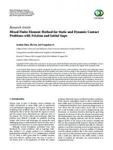
3. Results After entering the loading and boundary conditions, FEA analyses were solved. Von-Mises stress values occurred in femur was seen in Figure 4. While the highest stress and deformation have
occurred in bending loading type (172 MPa and 38.125 mm), the lowest stress and deformation (0.92 MPa and 0.04 mm) have occurred in torsional loading type as seen in Table 2. So, the bending loading type has lowest safety factor as 0.77.
Figure 4. von-Mises stresses under the different loading types Table 2. Stress values occurring in femur model No
Loading Type
1 2 3 4
Compression Tension Bending Torsional
Values Deformation (mm) 2.06 2.06 38.125 0.04
Stress (MPa) 15.70 15.70 172 0.92
4. Conclusions In this study, we analysed using finite element method of biomechanical behaviours of human femur model under the different loads. Femur bone was exhibited that the best stabile behavior under the torsional loading. The reason is due to the bone structure. On the contrary to this situation, the femur model under the bending loading type has lowest safety factor due to high stress and deformation and this data very important for post-op rehabilitation period. Therefore, type of loading on the femur is crucial for surgical procedure and rehabilitation approaches. The force was applied to only femur head
Safety Factor 11.64 8.69 0.77 >15
whereas there are many muscle forces. In addition to this situation, material properties of femur bone were considered as linear elastic material model. 5. References [1] Atmaca H, Kesemenli C, Memişoğlu K, Özkan A, Celik Y. Changes in the loading of tibial articular cartilage following medial meniscectomy: a finite element analysis study. Knee Surg Sports Traumatol Arthrosc 2013; 21(12):2667-2673.
Journal of Engineering and Fundamentals (JEF)
-46-
Journal of Engineering and Fundamentals (JEF), 1(1);43-47, 1 December, 2014
[2] Inal S, Taspinar F, Gulbandilar E, Gok K. Comparison of the biomechanical effects of pertrochanteric fixator and dynamic hip screw on an intertrochanteric femoral fracture using the finite element method. The International Journal of Medical Robotics and Computer Assisted Surgery: 2014;doi:10.1002/rcs.1584 [3] Gok A, Inal S, Taspinar F, Gulbandilar E, Gok K. Fatigue behaviors of different materials for schanz screws in femoral fracture model using finite element analysis. Optoelectronics and advanced materials-rapid communicatıons 2014; 8 (5-6):576-580 [4] Atmaca H, Özkan A, Mutlu İ, Çelik T, Ugur L, Kisioglu Y. The effect of proximal tibial corrective osteotomy on menisci, tibia and tarsal bones: a finite element model study of tibia vara. The International Journal of Medical Robotics and Computer Assisted Surgery 2014; 10 (1):9397. [5] Bessho M, Ohnishi I, Matsuyama J, Matsumoto T, Imai K, Nakamura K. Prediction of strength and strain of the proximal femur by a CT-based finite element method. Journal of Biomechanics 2007; 40 (8):17451753. [6] Ota T, Yamamoto I, Morita R. Fracture simulation of the femoral bone using the finite-element method: How a fracture initiates and proceeds. J Bone Miner Metab 1999;17 (2):108-112. [7] Sowmianarayanan S, Chandrasekaran A, Kumar RK. Finite element
analysis of a subtrochanteric fractured femur with dynamic hip screw, dynamic condylar screw, and proximal femur nail implants — a comparative study. Proceedings of the Institution of Mechanical Engineers, Part H: Journal of Engineering in Medicine 2008; 222 (1):117-127. [8] Yu X-z, Guo Y-m, Li J, Zhang Y-q, He R-x. Finite element analysis of impact loads on the femur. Chin J Traumatol 2007; 10 (1):44-48. [9] Senalp AZ, Kayabasi O, Kurtaran H. Static, dynamic and fatigue behavior of newly designed stem shapes for hip prosthesis using finite element analysis. Materials & Design 2007; 28 (5):1577-1583. [10] Kayabaşı O, Yüzbasıoğlu E, Erzincanlı F. Static, dynamic and fatigue behaviors of dental implant using finite element method. Advances in Engineering Software 2006; 37 (10):649-658. [11] Kayabasi O, Ekici B. The effects of static, dynamic and fatigue behavior on three-dimensional shape optimization of hip prosthesis by finite element method. Materials & Design 2007; 28(8):2269-2277. [12] Yuan-Kun T, Yau-Chia L, Wen-Jen Y, Li-Wen C, You-Yao H, YungChuan C, Li-Chiang L Temperature Rise Simulation During a Kirschner Pin Drilling in Bone. In: Bioinformatics and Biomedical Engineering , 2009. ICBBE 2009. 3rd International Conference; June 2009; 11-13:1-4. (Beijing)
Journal of Engineering and Fundamentals (JEF)
-47-