inverse conversion, from RNS to analog, has been satisfactory solved ... The paper is organized as follows: in section 2 the most diffused ... These methods are frequently oriented ..... Consequently our method doesn't limit either the number of ...
Residue Arithmetic Techniques for High Performance DSP ROBERTO LOJACONO, GIAN CARLO CARDARILLI, ALBERTO NANNARELLI, MARCO RE Electronics Engineering Department University of Rome “Tor Vergata” Via di Tor Vergata, 110 – 00133 Rome ITALY Abstract: - This paper is focused on the crucial point of the use of Residue Number System (RNS) arithmetic in actual applications, i.e. the conversion from residue arithmetic to binary representation. Some of the most recent contributions in literature are considered and compared with the work developed by the authors on this conversion problem. It is shown that all the reviewed methods present particular features, and that the best choice strongly depends on the particular DSP application involved. Key-Words: - RNS arithmetic, CRT conversion, RNS to binary conversion
1 Introduction Residue Number System arithmetic (RNS) for long time has been considered as an interesting theoretical topic without really actual applications. In the recent past years, however, it has gained increasing importance in key sectors as public-key cryptography, which requires multiplication of very large numbers [1], and, more recently, in the Code Division Multiple Access (CDMA) and parallel transmission systems [2,3]. The traditional use of this kind of arithmetic in fast DSP processing, initially limited to particular stand-alone processors, is also going to a complete integration with the binary systems. These new applications allow exploiting the advantages of the carry free characteristic of RNS arithmetic. That leads to obtain highly parallel data processing structures. However, the input and output conversions, from binary representation to RNS and, vice-versa, from RNS arithmetic to conventional binary, still remain the bottlenecks in the realization of RNS DSP processors. The input conversion, from binary to RNS, has been quite satisfactory solved many years ago [4]. The direct conversion, from analog to RNS, which represent a very hard problem from the point of view of the reliability of the results, is under study by many researchers and some interesting solutions have been proposed[5,6]. The inverse conversion, from RNS to analog, has been satisfactory solved [4] but, unfortunately, it is of poor interest in actual applications. Indeed in the present world, that is largely based on the digital technology, the most useful conversion is from RNS to binary representation. This paper focuses
on this last problem. Some of the conversion algorithms proposed in the recent literature are considered and compared to the work developed by the authors. The paper is organized as follows: in section 2 the most diffused methods for facing the conversion problem, namely those based on the Chinese Residue Theorem (CRT), are described. Section 3 recalls the CRT based implementation discussed in [7] (it improves the results described in [8]) Moreover, a comparison presented in [7] is discussed. In section 4, the CRT conversion developed in the past by the authors [9] is briefly reviewed. A discussion of the different features of the two methodologies, with reference also to other results available in the literature [10,11], is given in section 5. Concluding remarks are given in section 6.
2 RNS to Binary Conversion As already mentioned, there exist different methodologies for implementing RNS to binary converters. These methods are frequently oriented toward specific moduli sets and cannot be generalized to more general classes. Since new design approaches normally exploit automatic block generation and/or reusability, a main objective is the definition of general-purpose structures for the RNS to binary convertion. Using the CRT we can compute the binary number X starting from its RNS representation based on a
{m } , with
i = 1,2,.....N . Indeed, given a set of N residue numbers xi , there set of coprime moduli
i
exists only a number X < m1 m2 ... mN =M such that xi = X
mi
for i = 1,2,.....N . Using the CRT
we can compute this number by means of the following expressions N
X=
å m�
i
i =1
m� i−1 x i
mi
= H
M
� mi
mi
� mi−1
2 2n + 2 n 2 n −1 2n 2 −1 2n − 1 2 2n − 2 n 2 n −1 + 1 � � −1 Tab. 1. Values of mi and mi for the set
2n − 1 2n 2n + 1
(1)
M
(2 n − 1, 2 n , 2 n + 1)
ˆ i represents the partial modulus defined as where m m� i =
M � i−1 is and and its multiplicative inverse m mi
ˆ i−1mˆ i such that m
mi
= 1.
As shown in equation (1), the realization of a CRT based converter requires a final modulo computation. This operation represents one of the major bottlenecks in the hardware implementation. That is mainly due to the large value of the final M modulus and to the dynamic range of the term H. These difficulties increases with the growing of the number of moduli used in the RNS arithmetic. In fact, considering the CRT equation, we obtain the following bounds for H N
0 ≤ H = å m� i xi m� i −1 i =1
N
mi
≤å i =1
M (m − 1) < NM mi i (2)
modulo M operation is avoided by using a redundant representation N � � X = å mi mi−1 xi i =1
mi
−α M
(3)
The value of α is in the range [0, N-1], but its determination is not trivial. In [7] a particular decomposition of the CRT reconstruction formula is used
X =
ê x mi ê mˆ i L mˆ i ê å ê mˆ j i =1 ê ê ë L
x mi
i =1
mˆ i
+ å mˆ i
mi
ú ú ú ú ú ú û
mˆ j + (4) mj
−ε ⋅M mi
Equation (2) shows that the range of H is directly related to the number N. Moreover, if we are interested in maintaining the generality of the procedure, the final modulus M cannot be constrained and operation cannot be simplified.
Moreover, a theorem in [7] demonstrates that the value of ε is always zero for X in the range R < X < M, where R assumes the value
3 Method Suitable for Moduli Close to Powers of Two
é L é L ù ù R = ê å ê ∏ mk ú (mi − 1)ú − mˆ j úû ëêi =1,i ≠ j ë k =1,k ≠i ,k ≠ j û
As pointed above, the CRT reconstruction is a complex operation. In the literature, two main approaches are presented to address this problem. The first approach is limited to moduli sets, which are very close to powers of two. This particular set of moduli greatly simplifies the calculation of the � � quantities mi and mi−1 that are, respectively, the partial modulus and its multiplicative inverse mentioned above. This calculation, for the three moduli set ( 2 n − 1, 2 n , 2 n + 1) , gives the values shown in Table 1. The second approach directly addresses the CRT conversion problem in the general case, i.e. without constraints on the moduli set. Generally, the final
mˆ j
(5)
In [7] a comparison of the proposed general algorithm is given for the classical modulus set (2 n − 1, 2 n , 2 n + 1) . This comparison shows that, starting from the proposed general approach, the particularization of the algorithm gives some improvements with respect to other approaches proposed in the literature [10].
4 A Method for Computation
the
Modulo
In [9] the authors faced the problem of the CRT implementation proposing a new method for the computation of the modulo M operation.
To obtain a more suitable form of modulo operation, let us consider the number 2 k X , being k a suitable integer quantity. Applying CRT to the number 2 k X we obtain N
k
2 X
=
M
å m�
i
i =1
2 xi m� i k
−1
(6)
mi
M
The terms of the summation in Eq. (6) have the same dynamic range given by (2) since the factor 2 k appears inside a mod mi operation. The mod M operations in Eq. (6) can be rewritten as N
2 k X = å m� i 2 k xi m� i −1 i =1
mi
−α M
(7)
where α comes from the two modulo operations. From (7) we get N
X =
å m� i =1
i
2 k xi m� i −1
mi
−α M
2k
~ H −α M = 2k
(8)
The term αM of (8) can assume either positive or negative values. From the last term of (8), it is possible to bound the ~ value of α . In fact, if the term H is bounded in the ~ ~ range 0 ≤ H ≤ H + , α will lie in the interval (9)
Introducing the bounds given by Eq. (2) in Eq. (9) we obtain
− 2k < α < N
(10)
Eq. (8) suggests a very efficient method to ~ compute X starting from H . In order to obtain ~ integer values of X, the value H − αM must be a multiple of 2 k , i.e. the least significant k bits of ~ H − αM are zero. This means that the correct value of α belongs to the set
{
2k ≥ N − 1
αM
2k
~ = H
2k
}
(11)
where I is the set of integer numbers. This set only ~ depends on the k least significant bits of H .
(12)
the N + 2 k − 1 values of αM can be computed starting from the 2 k greatest values stored in a proper look-up table. In fact, since X must be a ~ positive number, the quantity H − αM must be positive. If this does not happens, the obtained value of α ∈Ω is incorrect. From (10) and (11) the correct value is obtained by subtracting 2 k from the incorrect one. So, if α ′ is the incorrect value obtained by the look-up table and α is the correct one, X is obtained by
~ ~ H − αM H − α ′M X= = +M 2k 2k
(13)
The following steps can summarize the procedure deriving from Eq. (13) • • •
~ H+ − 2k < α ≤ M
Ω = α ∈ I:
Using these bits we are able to select only 2 k values of αM , of the N + 2 k − 1 possible values, positive and negative, according to Eq. (10). If k is chosen such that
The term α ′M is read from the look-up table ~ addressed by the k least significant bits of H . ~ The sum H − αM is computed and the k least significant bits are discarded. If the result of the above step is negative the modulus M is added.
The conversion of the output number into a two’s complement representation can be performed by considering the following aspects. In general, if the number X is in the range [0, (M-1)/2] an output positive quantity is obtained. On the other hand, if (M+1)/2< X < M the output corresponds to a negative number. In the latter case a quantity M must be subtracted with a two’s complement subtractor to obtain the correct result. In our case initially we add the quantity (M-1)/2 obtaining that the positive numbers are now in the range [(M-1)/2, M-1] and the negative numbers are bounded in the remaining interval [0, (M-3)/2]. The two’s complement value can be obtained by ~ ~ subtracting from H the value [(M-1)/2, if H is positive, or adding the quantity [(M+1)/2] in the ~ case of negative value of H . The above algorithm corresponds to the following steps. 1. Computation of the quantities M −1 si = m� i 2 k m� i−1 ( x i + ) 2 m1
~ ~ H − α M 1641 − 3465 X= = = −456. 4 2k that is a negative number. Consequently, the final
N
~ 2. Computation of the summation H = å si ~ 3. Compute the quantity X~ = H − αk ′M 2
i =1
x1
x2
xN
Look-up Table
Look-up Table
4. The two’s complement result X C is obtained as
~
~ M +1 XC = X + 2
if X is negative Look-up Table
~ if X is positive
~ M −1 XC = X − 2
m�1 2 k m�1−1 ( x1 +
M −1 ) 2
m1
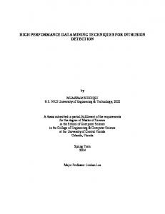
4.1 Hardware Architecture The implementation of the algorithm is shown in Fig. 1. The structure is based on an array of small look-up tables that store the terms M − 1 m� 2 k ( x + )m� −1 . The input look-up tables i
i
2
i
k
m� N 2 k m� N−1 ( x N +
Carry Save Adder Tree
M −1 ) 2
mN
s = élog 2 ( N * M )ù s-k
Look-Up Table
Adder
SIGN
mi
are very small and fast because we use a number of small moduli for implementing a large dynamic range. A tree of adders that implement the summation follows this input stage. The final modulo operation is obtained implementing Eq. (13) by using two adders and a look-up table containing 2 k words, each of n = log2 M bits. For example let us consider the implementation of a 32-bit arithmetic using the eighth moduli {7, 11, 13, 17, 23, 25, 27, 29}. With this moduli the lookup tables storing the terms m� 2 k ( x + M − 1)m� −1 i
i
2
i
mi
require for the addressing from 3 to 5 bits. Moreover the look-up table of the final modulo operation requires only 8 words of 32 bits each. This table can be realized by sparse logic or by using a set of multiplexers.
4.2 Numerical example Let consider the RNS composed by the six moduli {3,5,7,11 }, M=1155, N=4. For this set Eq. (12) give k=2. The look-up table stores all the multiples αM corresponding to positive value of α in the range 1≤ α ≤ 4. Considering for example the value X=122. It corresponds to the residue set {2,2,3,1}. Applying ~ CRT as described in Eq. (8) we obtain H =1641. Addressing the look-up table by using the two least ~ significant bits of H namely a bit string 01 the multiple of α M corresponding to α = 3 is
~
selected. Consequently X becomes
−
M −1 2
>0
Adder
Mux