1
Resolving Cross-layer Conflict between Overlay Routing and Traffic Engineering Srinivasan Seetharaman, Volker Hilt, Markus Hofmann, and Mostafa Ammar Abstract—Overlay routing is known to cause undesired instability in a network by operating in a selfish manner. The objectives of overlay routing, such as optimizing end-to-end latency, are often in conflict with the objectives of traffic engineering in the native layer, which is concerned about balancing load. In our work, we build on past research that has investigated the recurring non-cooperative interaction between overlay routing and traffic engineering, and develop strategies that improve the routing performance of a particular layer with incomplete information about the other layer. In our strategies, one layer acts as a leader that predicts the follower’s reaction and undertakes countermeasures to prevent future deterioration in performance. Specifically, we propose two classes of strategies – friendly or hostile – for each layer. By simulating under different network characteristics, we show that these preemptive strategies achieve near-optimal performance for the leader and increase the overall stability of the network. Furthermore, we observe that the best performance for a particular layer is achieved only when the goals of the other layer are completely violated, thereby motivating a higher level of selfishness. Index Terms—Overlay routing, Traffic engineering, Strategies, Interaction, Game theory
I. I NTRODUCTION Overlay networks have recently gained attention as a viable alternative to overcome functionality limitations (e.g., lack of QoS, difficulty in geo-positioning, multicast support) of the Internet. The basic idea of overlay networks is to form a virtual network on top of the physical network so that overlay nodes can be customized to incorporate complex functionality without modifying native routers. These virtual networks have been designed with the capability to sense changes in the underlying native network and dynamically adapt their routing tables. This is a selfish approach aiming to offer enhanced routing performance to the overlay network’s traffic. In a resource-constrained world, where the native layer performs traffic engineering (TE) to balance load on native links, the selfish behavior of overlay routing tends to backfire and causes all traffic to suffer route oscillations, increased routing cost and resource starvation[2], [3], [4]. Further, instability and sub-optimality is exacerbated when there is a conflict in objective between the two entities, viz. overlay routing that aims to minimize the latency between the nodes of a service overlay network[5], and traffic engineering that aims to balance the load S. Seetharaman is a member of Deutsche Telekom R&D Lab, Los Altos, CA 94022, USA. email:
[email protected] V. Hilt and M. Hofmann are with the Bell Laboratories, Alcatel-Lucent, Holmdel, NJ 07733, USA. emails: {volkerh,hofmann}@bell-labs.com M. Ammar is with the College of Computing, Georgia Institute of Technology, Atlanta, GA 30332, USA. email:
[email protected]. Srinivasan and Mostafa were supported in part by NSF grant CNS-0721559. An earlier version of this work was presented at IEEE INFOCOM 2007[1].
in the underlying native network[6], [7], [8]. Although this noncooperative interaction is a well-studied problem, past research does not suggest ways to avoid associated shortcomings and attain an optimal operating point. In this context, our goal is to propose strategies that obtain the best possible performance for a particular layer by predicting or counteracting the other layer’s reaction, while steering the system towards a stable state. This is similar to the Stackelberg approach where one player acts as a leader and the other players are selfish followers[9]. We refer to the layer that makes the first unconventional route adjustment as the leader and the layer that reacts to this change as the follower. As these strategies allow one layer to firmly assert its performance, without any future deterioration, we refer to them as preemptive strategies. The general idea is to insure that the leader picks those optimal routes for which the follower has no other alternative or volition but to retain the same routes. Specifically, we propose preemptive strategies for the following two scenarios: 1) When overlay applications can estimate the characteristics of the underlying native network and can sufficiently predict its behavior for a certain load distribution. In the context of service overlay networks, the objective of the leader is to minimize the end-to-end latency of the overlay paths. 2) When the native network is aware of the selfish overlay network and can sufficiently predict its behavior for a certain network topology. In the context of traffic engineering, the objective of the leader is either to minimize the maximum link utilization, or to minimize the overall network cost. Unfortunately, prediction in the true sense is not a pragmatic solution owing to three main issues. Firstly, overlay networks and native networks maintain independent routing tables and have different network span, making it unrealistic to procure complete knowledge about the other layer’s functioning. Secondly, the prediction process makes it essential to contrive a relation between the latency objective and the load balancing objective, which does not exist in reality. Lastly, determining the exact routes to be prescribed by each layer, even in the presence of complete information, is a hard problem[10]. We work around these limitations by profiling the crosslayer interaction, and propose simple strategies for the leader to proactively prepare itself for the follower’s reaction (response). As this represents a repeated game[11], where the players have continuous sequential interaction, it is possible to capitalize on historical observations and to gradually learn the desired action. Specifically, we propose two classes of strategies – friendly or hostile – for each layer. In the friendly strategy, one layer picks routes in such a manner that it improves its performance without defeating the objective of the other layer. The fundamental idea behind the
Yong et al.[15] propose proactive overlay routing algorithms that provide shortest paths, while constantly improving the headroom on each link. This tends to have the same effect as minimizing the maximum utilization and reduces the impact of overlay traffic, thereby reducing the conflict in objective. However, this solution is plagued with instability issues, which is precisely what our strategies eliminate. Jiang et al. [16] study interactions among multiple selfish routing overlays using a game theoretic model, where each overlay seeks to minimize its weighted average delay. Their work helps improve routing performance, but fails to capture the effects of cross-layer interaction. In the past, we investigated the interaction between BitTorrent file-sharing protocol and inter-domain TE[17]. The selfish behavior of the BitTorrent protocol, where the performanceawareness constantly alters the routing decisions (peer and piece selection), causes serious fluctuations in the load experienced by the underlying native network. When the native layer deploys inter-domain TE, we observe cross-layer conflict similar to that in service overlay networks. However, the conflict manifests more as a contention for bandwidth between the BitTorrent peers and inter-domain TE. Korilis et al.[9] investigate using Stackelberg approaches for optimizing the overall network performance, by deploying a manager that distributes its traffic after predicting the response of the other users in the network. However, in their work, the objective of all players are aligned and reflect the M/M/1 delay function. Hence, it is not as applicable when the objective is conflicting. Moreover, they assume knowledge of the follower’s response (input + objective function), which is not feasible in reality. Similarly, the work in [10], which uses a Stackelberg approach to improve the performance of the overlay layer, also assumes complete information of the follower and a M/M/1 cost function for the two layers. Our preemptive strategies do not make these assumptions, and considers conflicting objectives between the two layers, without requiring complete information about the other layer. Furthermore, they use a gradient projection search to obtain an approximate solution, which is locally optimal and closer to the initial point, in one iteration. In contrast, our strategies arrive directly at the optimal choice within a few rounds, and is unrestricted by the original solution space.
friendly design being that the follower does not get instigated to react if the leader operates within certain bounds acceptable to the follower. On the other hand, a hostile strategy improves the performance of one layer primarily by defeating the objective of the other layer, with minimal chance for recuperation. The fundamental idea behind the hostile design being that the leader can cause irrecoverable problems for the follower in an effort to leave the follower no viable option to react. As overlay applications proliferate[12], it is highly likely that the amount of selfish overlay traffic will experience significant growth in the future. Moreover, network virtualization through overlay networking is seen by many as a potential future for the Internet[13]. This tends to alarm the current ISPs about the impending destabilization of its network. In such a context, deploying our strategies in either layer is crucial to eliminate the instability (persistent route oscillations) generally observed in the non-cooperative interaction[3], [4], [14], without compromising on route optimality. Though we do not recommend the hostile strategies, we propose and analyze them in this paper to prepare each layer for possible hostile attacks from the other layer in the future. Our contributions are four-fold: 1) We provide an understanding of the objective conflict in the cross-layer interaction and its detrimental effects. 2) We develop means to mitigate the inherent instability in the system without compromising on the routing performance. 3) We propose simple, yet effective, strategies that help a particular layer achieve near-optimal performance, with limited information of the other layer. 4) We illustrate the effectiveness of our strategies, and show that when both layers adopt a preemptive strategy the cross-layer interaction is similar to the Prisoner’s dilemma game. The remainder of this paper is organized as follows. We briefly describe related work in Section II. We present the issues involved in the interaction and the model for evaluation in Section III. We characterize the behavior of the cross-layer interaction in Section IV by a simulation study. Sections V and VI propose preemptive strategies that improve the performance of the overlay layer and native layer respectively. Section VII presents the performance achieved when both layers adopt a preemptive strategy. In Section VIII, we discuss the issues with deploying multiple overlays and present some special strategies for the inter-domain scenario. We summarize this paper in Section IX.
III. C ROSS - LAYER I NTERACTION : M ODEL In this section, we describe the exact behavior model of each layer and list the important performance metrics of the crosslayer interaction. We assume that the two layers are independently operated by different administrative entities, which is often the case. This introduces a certain level of selfishness.
II. R ELATED W ORK Our work builds directly on [2], which addresses the question of whether the multi-layer system with conflicting objectives will reach a steady state. However, unlike our work, they do not derive means to resolve the detrimental effects. Another related work analyzes the cross-layer interaction as a Nash routing game with each layer aiming to optimize its cost[3]. Even though the two players in the system are non-cooperative, their objective is similar. This similarity in objective is, however, unrealistic in most scenarios where no direct transformation exists between the application specific metric (like end-to-end latency) and native link load.
A. Network Model We investigate the interaction between the following two entities: 1) Traffic Engineering: TE is a crucial procedure in modern ISP networks to balance load and remove bottlenecks. Typically, it uses a particular snapshot of the traffic demand matrix to derive the set of routes that achieve a specific load-balancing 2
objective. The frequency of re-engineering the routes depends on the amplitude of change in the traffic matrix or the desired periodicity. This operation can be performed both on interdomain links and on intra-domain links. The behavior and the methodology vastly differ with both flavors. Intra-domain TE is used to balance load across all links within the AS. We study the effects of adopting one of the following two intra-domain TE objectives: •
•
Overlay routing
Overlay layer Native link delays
demands Demand on each overlay link
Prop. delay
Minimize the overall cost of the network (as proposed by [7]), where the cost φ(a) of a native link a is modeled using a piecewise-linear, increasing, convex function of the load. Minimize the maximum link utilization in the network (as used by [18], [19]), where the utilization of an individual link a is defined as the ratio between the cumulative load Xa in the link and the capacity Ca of the link.
Native routes
Queuing delay computation
Fig. 2.
Traffic Engg
Load on each link
TM
Background traffic demands
The indirect feedback loop between overlay routing and TE.
where the queuing delay is negligible in comparison to the propagation delay and one where it is non-negligible. 2) Overlay Routing: We focus on a service overlay network, which is managed by a single operator, and which offers latency-optimized paths to actual end systems. To achieve this, the overlay layer maintains a routing table that is independent of the underlying network[21], [22], [23] and deploys some form of dynamic routing to adapt to changing conditions in the native network. Following standard terminology, an overlay link represents the direct native route between two overlay nodes, which in turn comprises of one or more native links, and an overlay path is made up of one or more overlay (virtual) links. This overlay path represents the end-to-end route taken by the application traffic. We model the overlay network as a directed graph G′ = (V ′ , E ′ ), with V ′ being the set of nodes and E ′ being the set of edges. We assume that the overlay topology is given and aim to improve over current performance. We assume complete mesh connectivity of overlay links between the overlay nodes. The overlay network periodically monitors the state of the overlay links and the latency incurred by each of them. Based on the collected data, the overlay performs some form of link state routing to optimize its objective.
Intra-domain TE can be implemented by means of MPLS[20], where the traffic between two nodes is partitioned and transported over one or more pre-configured tunnels, or by means of OSPF/ISIS[7], where the IGP link metrics are optimized to approximate the solution of MPLS-TE. On the other hand, inter-domain TE is used to balance load across all ingress or egress inter-domain links. It is also possible that an AS will want to reduce the overall cost incurred, when the individual inter-domain links have certain weights (often to reflect the monetary cost incurred). In our work, we focus on ingress and egress TE that attempts to solve the following optimization problem: •
Overlay routes
Minimize the maximum link utilization across interdomain access links. For each source or destination AS, the optimal solution will determine the amount of traffic routed over each access link.
Inter-domain TE for egress links can be achieved by using a combination of local_pref attribute and IGP weights to include the choice of the appropriate border router, once the route for each destination prefix is computed. Inter-domain TE for ingress links can be achieved through a combination of selective advertisements, wherein an AS advertises certain prefixes through a particular inter-domain link, and AS-path prepending, wherein an AS artificially concatenates more AS numbers on the advertised path so as to inflate the AS path length attribute[8]. We understand that the reality in inter-domain TE solutions cannot achieve this level of granularity, especially when some strategies aim to influence the decision of ASes a few hops beyond their adjacent ASes. However, we still adopt this model in our work in order to get an idea of worst case behavior. Most of the discussion in this paper is targeted at intradomain TE, although the observations and results are equally common to inter-domain TE as well. Further, we only present results from the interaction between overlay routing and MPLSTE, as MPLS achieves the optimal TE objective. We model the native network as a directed graph G = (V, E), where V is the set of nodes and E is the set of directed links with finite capacity constraints. The latency of each physical link is the sum of the propagation delay and the queuing delay. We analyze two different cases in the rest of the paper: one
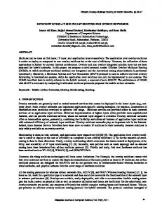
B. Interaction between the Layers Each entity described above operates solely on the results of the network monitoring process and is otherwise oblivious to the dynamics of the other layer. However, the independent routing decision of each layer influences the operation of the other layer, as illustrated in the closed control loop in Fig. 2. This independent operation of routing protocols in the two layers, as seen in today’s networks, has the following two inherent drawbacks: • Misalignment of objectives: In the attempt of deriving shortest paths, overlay routing tends to reuse a short overlay link in multiple paths1 . This causes the load on that native route to escalate beyond the expected demand, thereby upsetting traffic engineering. Similarly, in an effort to balance load, TE may offer native routes that span under-utilized routes in remote regions of the network, causing a stretch in the overlay link latency. This shows a serious misalignment in objectives leading to contention and associated route oscillations. 1 It has been shown on a Planetlab testbed that the popularity (betweenness) of certain nodes in the overlay network is non-uniformly distributed[24].
3
0 14 ms
Overlay node
3 4 ms
A
Link load
Multihop paths: A−>B−>C A−>B−>D 2 6 ms
Multihop paths: A−>B−>C A−>B−>D 2 4 ms
C
B
3 5 ms
A
1 5 ms
2 10 ms
0 23 ms
0 14 ms
Multihop paths: A−>B−>C−>D A−>B−>C B−>C−>D 4 4 ms
C
B
3 4 ms
A
1 5 ms
2 10 ms
0 23 ms
D
0 14 ms
3 5 ms
0 10 ms
0 23 ms
D
C
B
D
OVERLAY NATIVE
2 10ms
E 0 2ms
0 2ms
F
Native router
1
B
A
4ms
2 3ms
2 3ms
I
2 10ms
2 2ms
2 3ms
G 1 6ms
J
2 10ms
E
F
C
4 2ms
Overlay link Native link
4 2ms
2 10ms
1 2ms
H
SPLIT A
2 2ms
1 3ms
D
1 2ms
3
B
4ms
AFTER OVERLAY TRAFFIC IS INTRODUCED t=1
4 2ms
2 3ms
G 1 6ms
2 10ms
J
2 10ms
E
F
C
2 2ms
1 3ms
I
2 2ms
2 10ms
AFTER TE REACTS t=2
D
1 2ms
H
SPLIT A
2 2ms
1 3ms
C
0 2ms
1 2ms
5
B
4ms
1 3ms
I
0 2ms
2 10ms
4 2ms
0 3ms
H
G 3 6ms
J
2 10ms
0 2ms
D
AFTER OVERLAY REACTS t=3
Fig. 1. Illustration of 1 round of interaction between overlay routing and intra-domain TE. A routing decision at the overlay layer changes load experienced by the native layer, while a routing decision at the native layer changes latency experienced by the overlay layer.
set of edges E and φ is the summation of the piecewise integral of the cost increase function. • Maximum utilization, if the objective of the ISP is to minimize the maximum link utilization observed in its network, or across inter-domain access links. The maximum utilization is computed as maxa∈E X(a) C(a) , where a represents a link in the set of edges E . In our work, we focus on service overlays that offer lowest latency routing service. Hence, the routing performance of the overlay layer can be measured by: • Average latency, which is defined as the average of the end-to-end latencies observed across all overlay paths with non-zero traffic demand. When there exists a conflict in the objective between the two layers, the system tends to become unstable, leading to frequent alterations in the route taken by existing traffic. These changes in route can happen to all flows at the end of traffic engineering, or just to overlay flows at the end of overlay routing. Each such route change is referred to as a route flap. Route flaps can be a serious problem in case of TCP, VoIP and other traffic that relies on packet ordering and is sensitive to jitter[25]. This results in poor performance for the end-user. Moreover, the route flaps serve as an important indication of the instability in the system. Hence, the next performance metric of interest is: • Number of route flaps, which is the sum of route changes observed in existing flows after a routing operation. During the cross-layer interaction between overlay routing and TE, there are operating points where the performance of a particular layer is the best it can be. We refer to this performance as the best-case, or optimal, performance of that layer. This best-case performance can be computed as the minimum of the objective value attained in any of the rounds. However, that layer is usually unable to retain this best-case performance, as the other layer annuls it during its routing operations. The preemptive strategies we propose attempt to steer the system towards the best-case performance of the leader. However, as shown later, the leader is not always able to achieve the best-case performance, and sometimes incurs a minor loss of routing performance, as a tradeoff against the gain in system
Misdirection of traffic matrix estimation: The TE operation used by the ISPs relies heavily on the estimate of the traffic matrix. In the case of overlay networks, irrespective of the TE protocol or objective, the drawback is that the estimated traffic matrix is not reflective of the actual end-to-end source-destination demand[2], [4]. Hence, there is a certain amount of misdirection in the load-based optimization procedure of TE. For instance, consider the traffic on two overlay paths A − B and A − B − C . The traffic on the overlay link AB cannot be differentiated based on the true destination. This makes the load distribution process rigid. The interaction between overlay routing and traffic engineering is non-cooperative and recurring. Each layer optimizes the routes to suit its local objective in succession. We refer to the duration between two iterations of TE as a round. The number of overlay routing operations between two TE operations may vary based on the probing frequency. Fig. 1 illustrates this cross-layer interaction by means of a simple example. In the figure, the numbers indicate the available bandwidth on each native link and the latency value of each link in ms. We do not show the IGP metrics. We assume that the traffic is split evenly between available equal cost multipaths and the latency value of each native link is a constant parameter. The overlay traffic matrix contains 1Mbps of traffic from each node to every other node. We notice that any reconfiguration in one layer’s routes leads to a substantial change in the other layer’s state (link load profile in the case of TE or link latency profile in the case of overlay routing). Such a system takes longer to stabilize in the presence of resource constraints. The system in the example takes longer than 10 rounds to reach steady state. •
C. Performance metrics Based on the particular TE objective, the routing performance of the native layer can be measured by one of the following two variants: • Native cost, in the event the ISP chooses to minimize the overall cost incurred by its network. The native cost is P computed as a∈E φ(a), where a represents a link in the 4
overlay network. The overlay traffic and the background traffic together represent the total load on the native network. We vary the amount of traffic in the network by tuning two parameters – average link utilization u and the overlay traffic scale factor p. The former parameter determines the total load in the network and the latter determines the fraction of traffic on an overlay link that belongs to the overlay network. We configure the capacity of each native link in our topology to be 10Mbps. Once we determine the total load l (sum of all demands), we determine the source-destination pairs in the native network that are also part of the overlay. In all those pairs, we set the fraction of the overlay traffic to be p times the total load in those pairs. The remaining load becomes part of the background traffic. Once we know the total load in different sections of the native and overlay network, we randomly generate traffic demands between each source-destination pair. This traffic assignment is similar to that in [3]3 . We keep this traffic matrix the same all through our experimentation in order to analyze the dynamics for each load distribution. It is worth noting that the overlay traffic matrix has to be combined with the overlay routes to determine the overlay networks’ contribution to the real traffic matrix, as shown in the feedback loop of Fig. 2. An example of this operation can also be seen in Fig. 1. We configure the probing frequency in such a manner that each round of the interaction has one instance of TE, followed by three instances of overlay routing. After each TE, we update the latency of each overlay link and after each overlay routing operation, we update the real traffic matrix to reflect the changes. Thus, each layer’s action influences the other layer’s reaction. In our simulation, we determine the exact routes for MPLSTE by solving the linear program (LP) formulated in [7]. To solve this LP, we use the GNU linear programming kit[27]. We understand that our simulation setup can be considered simplistic i.e., it considers only a fixed native topology size of 20 nodes, intra-domain scenario and a single overlay network. However, we believe that this approach is well-suited to study each interacting element. We reserve consideration of multiple ASes deploying intra-domain TE and multiple coexisting overlay networks for future study.
stability. We use the following performance metric to estimate the effectiveness of the preemptive strategies we propose: • Inflation factor, which is defined for each layer as: Inflation factor =
•
Steady state obj value with strategy mint=0..∞ Obj value without strategy
In the leader’s case, this factor is used to determine if the leader achieved the best-case performance at the steady state, or if the leader had to accept a minor tradeoff to retain its stable performance. In the follower’s case, this factor reflects the amount of sub-optimality incurred by the follower, due to the leader’s preemptive action. Stabilization time, which is defined as the time taken for the route flaps to cease and the multi-layer system to attain an operating point acceptable to both layers. This value, represented in terms on the number of rounds needed to stabilize, gives an idea of the system’s stability.
IV. C ROSS - LAYER I NTERACTION : A SIMULATION STUDY In this section, we describe the setup of our simulation of the interaction between overlay routing and intra-domain traffic engineering, present results from the simulation study, and discuss about ideal routing choices for the leader. A. Simulation Setup In this subsection, we describe the simulation setup that we used to evaluate the performance of the cross-layer interaction in the intra-domain scenario (with or without the preemptive strategies). Clearly, the routing performance in this multi-layer scenario is topology-specific and load-specific. Hence, we simulate multiple overlay topologies over multiple native networks, with varying levels of traffic, to improve the generality of the results. We use GT-ITM[26] to generate random network topologies for the simulations. We generate 5 native network topologies of 20 nodes each2 , along with 5 random mappings of a fullyconnected 5-node overlay topology to the native topology and 5 random mappings of an 8-node overlay topology. This gives us 50 possible combinations, over which all observations in this paper have been verified. However, we present the results from only one topology to monitor the trend accurately. The results observed for this topology are representative of those observed in the other topologies, unless otherwise mentioned. The overlay links used in the simulation are bi-directional and we deploy a ping-like delay estimation scheme to determine the latency across an overlay link, i.e. we compute the round-trip time across each overlay link and halve the result to determine the one-way latency. We believe this to be the most realistic approach towards simulating overlay link metrics. This causes symmetric routing at the overlay layer, though the native TEbased routing over the set of directed links E is asymmetric. We posit there are a few overlay nodes in a domain that exchange a certain amount of overlay traffic among each other. In addition, all nodes in the domain exchange a certain other amount of background traffic, i.e. background relative to the
B. Simulation Results Fig. 3 presents results for the interaction between the two layers for a specific scenario, without applying any of our preemptive strategies. We observe that each TE procedure leads to an increase in the average end-to-end latency of existing overlay paths, while each overlay routing operation leads to an increase in the maximum utilization of the native network. This shows a clear conflict in objective between the two layers, and gives sufficient reason for the instability. Owing to the probing frequency, we observe that the duration of sub-optimality for TE is longer in comparison to that for overlay routing. Though we plot only 10 rounds of interaction, the conflict in objective extends even beyond 100 rounds.
2 We are restricted to a small native network owing to the huge computational complexity of the linear programming solution of MPLS-TE
3 There is a minor difference that we preset the total load first and then subtract the overlay traffic from it to determine the background traffic.
5
Min(Max util), with queuing delay, AvgLinkUtil=0.2, Scale p=0.8 (Overlay traffic=13%) 1
40
Max util
10
10 5
20 0 TE OR TE OR TE OR TE OR TE OR TE OR TE OR TE OR TE OR TE OR TE Event sequence
(a) Without queuing delay
Avg.latency
15
15
0.6 25
StdDev latency
Avg.latency
20
StdDev latency
0.6
0.8
15
# route flaps
0.8
# route flaps
Max util
Min(Max util), without queuing delay, AvgLinkUtil=0.2, Scale p=0.8 (Overlay traffic=13%) 1
40
20 15
10 5
20 0 TE OR TE OR TE OR TE OR TE OR TE OR TE OR TE OR TE OR TE OR TE Event sequence
(b) With queuing delay
Fig. 3. The progression of observed performance for a particular topology with 8 overlay nodes and 20 native nodes. The above results represent the base performance, without using any of our preemptive strategies. Here, the objective of intra-domain TE was to minimize the maximum utilization. Each TE event is followed by 3 overlay routing events.
of a second feedback loop in Fig. 2. In our simulation, the overlay layer did not employ any form of hysteresis to dampen these minor queuing delay-based route flaps. We extended our analyses by varying different parameters of the simulation (namely, TE objective, number of overlay nodes, amount of overall traffic, percentage of overlay traffic, and the queuing delay), in an effort to completely profile the scenarios where the conflict is exacerbated. We observed a performance similar to those plotted above, wherein the routes flap persistently without attaining steady state. Table I presents the ratio of the worst possible performance of a particular layer to its best performance (referred to as “max/min” in the table). Each value is an average of results from simulating 25 different overlay network combinations, as described earlier. We consider as “base scenario” the case with 8 overlay nodes, 20 native nodes, 0.2 average link utilization, 0.8 overlay traffic scale factor p, no queuing delay, and an objective of minimizing maximum utilization. Each entry in the table, thus, denotes a deviation from that scenario. The following is the summary of our observations:
The number of route flaps gives a numerical estimate of the instability in the network. We observe that the system suffers from persistent route flaps and does not attain a stable operating point even after 100 rounds elapse. This is accordance with earlier findings[2], which used both synthetic topologies and real tier-1 ISP topologies for verification. Note that the number of route flaps observed during TE serves as an estimate of the instability prevalent in all native routes, though we only plot the route flaps observed in the overlay traffic. We observe that the amplitude of variation in the maximum utilization and average latency values is different between Fig. 3(a), where the queuing delay is negligible compared to the propagation delay, and Fig. 3(b), where queuing delay is comparable to the propagation delay. We used the M/M/1 formulation of queuing delay for lack of an accurate model. This is sufficient since we qualitatively seek a delay function that is inversely proportional to the available bandwidth on the link. Moreover, we are only focussed on comparing the temporal variation of the layer’s outcome. On comparing Fig. 3(a) and Fig. 3(b), we observe that the introduction of queuing delay has reduced the amount of variation caused in the maximum utilization value. This can be attributed to the closed loop feedback inherent to queuing; when overlay routing picks a low delay link for multiple routes, it tends to increase the load on that link, leading to an increase in queuing delay, and consequently a cessation of using that link and a reduction of the load on that link. This indicates that the objectives of the two layers are less conflictive in the second scenario. Another interesting feature in Fig. 3(b) is the flapping of overlay routes triggered by the change in queuing delay, which in turn was caused by the shifting of load during the previous overlay routing operation4 . This shows minor unrest in overlay routing in the presence of substantial queuing delay, despite the absence of TE. We expect this behavior owing to the presence
•
4 Note that any change in the overlay routing table leads to a change in the real traffic matrix seen by TE, though we do not change the native or overlay traffic matrix.
6
When the TE objective is to minimize the native cost, the trend is fairly similar to that shown in plot Fig. 3. The max/min value of TE performance presented in Table I is much lower than that when the TE objective is to minimize the maximum utilization because the native cost is a sum of individual link costs, each of which have low influence on the total except during congestion. The max/min value of overlay routing is, however, almost equal to that observed when the TE objective is to minimize the maximum utilization. Thus, adopting native cost as the TE objective also leads to crosslayer conflict. The main difference is when the queuing delay is nonnegligible, wherein we observe that the objective of TE and overlay routing are lesser in conflict with each other. This is because the objective of minimizing native cost tends to keep the load on all links low (and not just the heavily congested link), thereby reducing queuing delay and consequentially
Base With With With With With With
•
•
•
•
scenario TE objective of min(cost) AvgLinkUtil = 0.1 AvgLinkUtil = 0.3 queuing delay scale p=0.4 only 5 overlay nodes
Max/Min for TE perf. 2.529 1.408 2.665 2.43 2.386 1.733 1.403
Max/Min for Overlay perf. 1.432 1.415 1.465 1.458 1.581 1.412 1.236
4.5
0.5 AS 1239; 315 nodes AS 6461; 141 nodes AS 3257; 161 nodes AS 3967; 79 nodes AS 1755; 87 nodes AS 1221; 108 nodes GT−ITM; 20 nodes
0.4 0.3 0.2 0.1 0 0.05
0.1 0.15 0.2 Fraction of nodes in overlay
(a) Level of misdirection
0.25
Avg paths using each overlay link
Scenario
Avg. fraction of paths that are multi−hop
TABLE I AVERAGE MAX / MIN RATIO OBSERVED IN DIFFERENT SCENARIOS .
4 3.5 3 2.5 2
AS 1239; 315 nodes AS 6461; 141 nodes AS 3257; 161 nodes AS 3967; 79 nodes AS 1755; 87 nodes AS 1221; 108 nodes GT−ITM; 20 nodes
1.5 1 0.5 0 0.05
0.1 0.15 0.2 Fraction of nodes in overlay
0.25
(b) Level of stress
Fig. 4. Reasons for potential cross-layer conflict in commercial ISP topologies. We plot our analysis of 6 ISPs inferred by the Rocketfuel project.
the average latency of the overlay paths. On the other hand, overlay routing avoids overloading links when queuing delay is non-negligible, thereby reducing the native cost. Hence, the conflict is lesser, yet significant, in the case where the TE objective is to minimize native cost and the queuing delay is non-negligible. We analyzed two sets of overlay topologies with 5 nodes and 8 nodes each. From the table, we observe that a higher fraction of overlay nodes causes higher conflict. This can be explained by inspecting the number of multi-hop overlay paths, defined as the overlay path which is not the same as the direct native route. A multi-hop overlay path is the primary reason why the native layer traffic matrix estimation is misdirected, i.e. when two nodes always communicate along the direct native route, then TE is able to load balance easily. Thus, more the number of multi-hop overlay paths, more the conflict between TE and overlay routing. In the 5node topologies, we observed few multi-hop overlay paths. This caused the smaller topology to have low level of conflict, while the 8-node topology profiled above possessed 20 multihop overlay paths, causing a higher level of conflict and a substantial number of route flaps. Irrespective of the size of the native topology and overlay topology, the occurrence of route flaps depends mainly on how conducive the overall network is to forming multi-hop overlay paths. Thus, we are justified in adopting a small native network, as long as there are sufficient overlay nodes. The total load in the network has little bearing on the level of conflict, although the seriousness of the congestion in the intra-domain links increases with increasing load. Further, we start seeing considerable amplitude in variation, even at an average link utilization of 0.1. We analyzed the effect of overlay traffic by setting the scale factor at 0.4, 0.8, 1.2 and 1.6. We observe higher variations in the TE objective as the scale factor is high. When the amount of overlay traffic is very small, overlay routing has minimal impact on TE outcome. This is inline with our intuition and with past research results[3]. Consequently, we find very low amplitude of variation when the scale is 0.4 (which represents overlay traffic that is 6.4% of the total traffic). This is confirmed by the results in Table I.
overlay nodes in each of the native networks. We, specifically, inspect the following two parameters: • Fraction of multi-hop overlay paths: This fraction gives an idea of the level of misdirection caused by overlay routing. As mentioned earlier, this parameter tends to be proportional to the level of cross-layer conflict. We observe that the fraction of multi-hop overlay paths grows rapidly as the number of overlay nodes increases from 5% to 15% of the number of native nodes. Furthermore, the fraction is much higher than that observed in our simulation setup, primarily due to the bigger scale of the overlay topology. • Average number of overlay paths using each overlay link: This parameter indicates the level of stress experienced by each overlay link, and consequentially by the native link. Higher the stress, higher is the objection and conflict from TE. We observe that this value also increases steadily as the number of overlay nodes in a topology increases. Furthermore, the value is much higher than that observed in our simulation setup. These parameters indicate that cross-layer conflict can be a serious issue in commercial ISPs when the size of the overlay network grows and the amount of overlay traffic surges. D. Time-scale of Traffic Engineering Efforts The aforementioned results are specific to relatively short time-scale of operation, viz. TE is performed after three instances of overlay routing. This can be considered too frequent from the perspective of the ISP and thus represent a worst case scenario. In the event TE is performed at a much lower frequency, the native layer suffers a much longer duration of sub-optimality. The peak in the maximum utilization objective of Fig. 3 will persist for a long duration, although the route flaps may not persist. Despite the improved stability, this situation is still objectionable to the native ASes. Thus, irrespective of the time-scale at which TE operates, the native layer TE objective is disrupted by overlay routing and there is a need to adopt mitigation strategies like those presented in Section VI. E. Social Optimum
C. Applicability to ISP Topologies
The social optimum is defined as the action-reaction pair that produces the best outcome for both the layers, and thereby serve as the ideal operating point for both layers. However, lack of sufficient knowledge to exactly predict the other layer’s response, makes it non-trivial to derive the social optimum. For
We inspect several real ISP topologies inferred by the Rocketfuel project[28] to get an idea of how susceptible these networks are to cross-layer conflict, and compare it with the simulation topology. Fig. 4 presents this analysis for different fractions of 7
TABLE II S TRATEGY PROFILE FOR EACH INPUT LOAD / LATENCY PROFILE P 1
P1
Action A3
Reaction R2 Reaction R3
Max util
Action A2
Follower Reaction R1
Outcome Latency′1 Load′1 Latency′2 Load′2 Latency′3 Load′3
instance, an overlay network that spans only a fraction of the native network, can only choose among the set of native routes it is exposed to and is unaware of a potential shorter route with lower load. Furthermore, the social optimum can also be inexistent in certain scenarios of conflicting objectives. Hence, we proceed to determine the best possible performance for a particular layer, even at the expense of the other layer.
0.8 0.6
Avg.latency
P1
Effect Latency1 Load1 Latency2 Load2 Latency3 Load3
20
StdDev latency
Leader Action A1
15
# route flaps
Initial P1
Load−constrained LP, Min(Max util), without queuing delay, AvgLinkUtil=0.2, Scale p=0.8 1
40
15 10
10 5
20 0 TE
Fig. 5.
F. Ideal Solution
OR
TE
OR
TE OR TE Event sequence
OR
TE
OR
TE
Performance results for the load-constrained LP strategy.
Given infinite learning time and memory, one can create a because TE does not find any alternatives besides the current map (as in Table II) of peremptory actions for the leader, which routing table. cause a specific reaction by the follower and an associated The strategies are classified, based on their nature towards change in outcome for the leader. Each entry can be created the native layer, as friendly or hostile. The friendly strategy based on history and by trying out all possible routing decisions. picks routes in such a manner that the TE objective is not The general idea is for the leader to replay any action that is altered much and the native layer still has a well-balanced load, known to yield a favorable (or favorable enough) outcome. It while the hostile strategy performs extra operations to achieve is worth noting that any choice in the strategy profile will be the overlay layer objective by defeating the TE objective. The acceptable to both layers, i.e. when the leader picks a certain observations made in this section apply to both TE objectives action, the final outcome after the reaction is bound to be and to both levels of queuing delay. agreeable to the follower. Clearly, there are intractable number of possibilities, for each load/latency profile. This makes it infeasible to determine in polynomial time the appropriate A. Friendly: Load-constrained LP routing decisions for each layer. In this strategy, we make use of the fundamental idea that In the following two sections, we propose preemptive strate- the TE sees only the real traffic matrix and not the end-togies targeting a particular layer, with the assumption that the end overlay traffic matrix. Hence, if we determine the load other layer does not deviate from its general objective. In distribution in the network after TE’s load balancing operation, addition, we assume that each layer has a general notion of the and ensure that any future routing at the overlay layer always other layer’s objective. Our strategies apply certain heuristics, contributes the same load to the real traffic matrix, then TE has based on the above study, to converge at a near-optimal routing no reason to be triggered. Using this reasoning, we adopt the table within polynomial time. Moreover, they do not require following algorithm for overlay routing: any other information besides what is report by basic network 1) Determine the available bandwidth on each overlay link using monitoring. Lastly, they require no cooperation or interface tools like Pathload[29]. Let us refer to the minimum of this between the two layers, and exercise sufficient control over value over all links as min(availbw). We insure that the the follower indirectly. Thus, these strategies can be easily available bandwidth on all links are kept above this value. implemented in a realistic environment. All simulations results 2) Set the maximum allowable load on each overlay link to the presented use native networks of 20 nodes, overlay networks amount of overlay traffic on that link, computed by a product of 8 nodes, average link utilization of 0.2, and an overlay of the overlay demand matrix and the overlay routing table. traffic scale p of 0.8. However, the results were verified over This is conservative because there might be more leeway. all synthetic topologies generated, as explained in Section III. 3) Set the maximum allowable load on each unused overlay link a, i.e. an overlay link that transports no overlay traffic, to a V. OVERLAY L AYER S TRATEGIES value of availbw(a) - min(availbw). This ensures that the TE objective is still respected. In this section, we present strategies that help the overlay (s,t) 4) Let F layer preemptively steer the cross-layer interaction towards a (x,y) represent the fraction of traffic between nodes s and t that goes over overlay link (x, y), and L(x, y) represent converging point, wherein the performance of the overlay is the maximum allowable load in the current round. Run the almost as good as the case when there is no reprisal from the following linear program (LP), with the last additional connative layer TE. By making certain calculated routing decisions straint, to determine the overlay routes. This LP minimizes at the overlay layer, we ensure that TE does not get triggered; the sum of latency of each overlay path, while insuring that because its network monitoring has not sensed any change, or 8
Dummy traffic, Min(Max util), without queuing delay, AvgLinkUtil=0.2, Scale p=0.8 1
X
(s,t)
F(x,y) −
X
(s,t)
F(y,z)
(y,z)∈E ′
(x,y)∈E ′
−1, if y=s = 1, if y=t 0, otherwise ∀y, s, t ∈ V ′
latency(s, t) =
X
delay(x, y) ×
(s,t) F(x,y)
(x,y)∈E ′
∀(s, t) ∈ V ′ × V ′ X
overlay demand(s, t) ×
(s,t) F(x,y)
0.6
Avg.latency
subject to:
0.8
30
StdDev latency
′ ×V ′
15
# route flaps
(s,t)∈V
Max util
the load on each overlay link is within the allowable limit. X latency(s, t) minimize Total Latency =
40
20 10
10 5
20 0 TE
≤ L(x, y)
(s,t)∈V ′ ×V ′
Fig. 6.
∀(x, y) ∈ E ′
OR
TE
OR
TE OR TE Event sequence
OR
TE
OR
TE
Performance results for the dummy traffic injection strategy.
Shift concern of TE: By sending dummy traffic, the overlay layer shifts concern of TE to the over-utilized native links and allows the other less loaded native routes to use the least possible resources. Thereby, making it more probable to obtain shorter native routes for the overlay links. Thus, sending dummy traffic prevents deterioration in overlay routing performance during future rounds. This strategy is counter-productive with regards to the overall system health. However, as long as the overlay links with dummy traffic do not intersect with overlay links we are truly concerned about, the risk incurred (in the form of queuing delay or packet loss) is minimal. Thus, we take special care that the links over which we send dummy traffic are i) unused by any overlay route, ii) non-overlapping with links under use. The latter constraint might require us to execute the traceroute program between the endpoints of each overlay link. Fig. 6 plots the simulation results for the case where we choke unused non-overlapping links. We observe that the overlay layer achieves good performance by completely violating the TE objective; The overlay layer incurred an inflation of 1.023, while the native layer incurred 1.992. The strategy was able to achieve good performance in the second round itself with no knowledge of previous load distribution and suffers no more route flaps. We realize that this strategy may not fare as well in the case where multiple overlay networks, coexisting over the same native network, inject dummy traffic simultaneously. This is especially problematic when the dummy traffic sent by one overlay network enters links used for regular traffic of another overlay network. In such cases, it is not feasible to guarantee good performance for every overlay network’s objective. An artifact of using a ping-like protocol for latency estimation in our simulation is that the queuing delay of the reverse links also matter. Hence, we take special care that the overlay links over which we send dummy traffic are non-overlapping in both the forward and reverse direction. •
Fig. 5 presents the simulation results for this strategy. In the first round of the simulation, we run a normal version of overlay routing (by setting all values in L to be ∞) to get an estimate of the optimal overlay routing performance. After the first round, we run the LP-version of overlay routing with finite load constraints. We notice that the overlay is able to reduce the average latency achieved without causing a substantial increase in the maximum utilization; The overlay layer incurred an inflation of 1.082, while the native layer incurred 1.122. Hence, it is a friendly strategy. Moreover, the above algorithm stabilized within one round and required data from only the previous round. The only drawback with this strategy being the added complexity in maintaining multipath overlay connections. The exact details of that are outside the scope of this paper. We also experimented with a gradient projection strategy, that shifts overlay paths from highly used overlay links to less used overlay links, while accepting a minor loss in performance. This serves as a form of load-balancing at the overlay layer, so as to prevent the TE from reacting. The reasoning behind such a strategy is that the popularity (betweenness) of certain nodes or links in an overlay network is much more than few others[24]. Hence, the gradient projection strategy tries to reduce this nonuniformity without causing a substantial increase in end-toend latency. However, the simulation results indicated that the overlay routing performance achieved by deploying this strategy is inferior to that achieved by the load-constrained LP strategy. B. Hostile: Dummy traffic injection In this strategy, the overlay layer sends high amounts of dummy traffic on unused overlay links with the following two motives: • Render TE ineffective: By sending high amounts of traffic, the overlay layer ensures that the objective of TE is stretched upto an extent where it becomes ineffective and has no effect on existing overlay routes. This gives the overlay layer complete freedom in picking routes and overloading certain links.
C. Performance Comparison Table III presents the values of the inflation incurred by each layer at the steady state and the time taken to stabilize, when the 9
TABLE III AVERAGE INFLATION FACTOR AND STABILIZATION TIME INCURRED BY
Max util
Hopcount−constrained LP, Min(Max util), without queuing delay, AvgLinkUtil=0.2, Scale p=0.8 1
OVERLAY LAYER STRATEGIES
Stabilization time (rounds) 2.92 4.92
Avg.latency
Load-constrained LP Dummy traffic injection
Inflation factor Overlay TE 1.058 1.151 1.072 2.613
# route flaps StdDev Latency
Strategy
overlay layer is the leader. Each value is an average of results from simulating 25 different overlay network topologies. We observe that the two strategies attain close to optimal average latency values. The friendly strategy sacrificed some of its performance to prevent distortion of the TE’s objective, while the hostile strategy achieved the best possible performance for the leader at the expense of the follower’s performance. From the stabilization time, we observe that the stability of the overall system is greatly improved.
0.8 0.6 30 20 10 15 10 5 40 20 0 TE
Fig. 7.
VI. NATIVE L AYER S TRATEGIES In this section, we present strategies that help the native layer preemptively steer the cross-layer interaction towards a favorable converging point. Similar to the previous section, the strategies are classified, based on their nature towards the follower, as friendly or hostile. The observations made in this section apply to both objectives of TE and to both levels of queuing delay.
OR
TE
OR
TE
OR TE OR Event sequence
TE
OR
TE
OR
TE
Performance results for the hopcount-constrained LP strategy.
load(x, y) =
X
(s,t)
demand(s, t) × f(x,y)
(s,t)∈V ×V
∀(x, y) ∈ E X
(s,t) f(x,y)
≤ 1.02 × H(s, t)prev
(x,y)∈E
∀(s, t) ∈ V × V A. Friendly: Hopcount-constrained LP In this strategy, we adjust the MPLS-TE formulation in such a manner that during each load balancing effort, it takes special care to keep the native routes at the same length as before. Thus, we insure that the overlay layer does not notice any change in the perceived overlay link latencies. This simple constraint on the native route length keeps overlay routing from being triggered, and helps retain the good load balance. To achieve this, we adopt the following algorithm at the native layer: (s,t) 1) Let f(x,y) represent the fraction of traffic between nodes s and t that goes over native link (x, y). This fraction is the output of the MPLS-TE’s LP formulation. 2) After each TE operation, compute the total hopcount H(s, t) of each native route (s, t). This can be computed as: P (s,t) (x,y)∈E f(x,y) . This hopcount profile H tends to approximate the latency profile of the overlay layer. 3) Using the hopcount profile of the previous round as input, compute the new set of native routes that are of almost the same length. The LP of MPLS-TE, with an objective of minimizing the maximum utilization, can be augmented to enforce this constraint in the following manner: minimize Maximum util = max
(x,y)∈E
The last constraint has been introduced to remove the need for overlay route change. We multiply the upper bound of the hopcount by 1.02 to allow the native layer a bit more flexibility in adjusting its routes, thereby allowing us to steer closer to the optimal load balance. Though, we restrict the hopcount and not the actual latency value, we reason that this approximation reduces implementation complexity and is sufficient to achieve good performance. Fig. 7 shows the simulations results for this strategy. TE learns the hopcounts used by each native route over the first 4 rounds and eventually obtains a hopcount profile that correlates well with the overlay link latencies. At that point, the LP was able to balance the load and keep the overlay link latencies the same, thereby leading to steady state. Moreover, we were able to achieve good performance for both the layers, as observed in the plot of the two objectives. The native layer incurred an inflation of 1.184, while the overlay layer incurred 1.027. We also experimented with an alternate strategy that tweaks the objective of traffic engineering, with an intent to attain stability indirectly. The goal of the strategy is to skew the load balancing process in such a way that it causes many links to achieve a link utilization in the range 0.3 - 0.6, and verify if this benefits system stability in the multi-layer scenario. The fundamental idea is similar in spirit to the work in [30], that makes the case for load unbalancing in server task assignment to improve the fairness in scheduling. For this counter-intuitive load unbalancing strategy, we observed near-optimal TE performance, while causing the oscillations to converge in 7 rounds. However, its performance is inferior to the hopcount-constrained LP strategy.
load(x, y) capacity(x, y)
subject to:
X
(x,y)∈E
(s,t)
f(x,y) −
X
(y,z)∈E
(s,t)
f(y,z)
−1, if y=s = 1, if y=t 0, otherwise ∀y, s, t ∈ V
10
TABLE IV AVERAGE INFLATION FACTOR AND STABILIZATION TIME INCURRED BY NATIVE LAYER STRATEGIES
0.8
Avg.latency
0.6 40
# route flaps # multihop paths StdDev latency
Max util
Increase latency, Min(Max util), without queuing delay, AvgLinkUtil=0.2, Scale p=0.8 1
15
Strategy Hopcount-constrained LP Load-based Latency tuning
20
Inflation factor Overlay TE 1.114 1.228 2.102 1.181
Stabilization time (rounds) 6.58 3.24
0
The above procedure gradually learns which native links are key to overlay network and tends to dissuade usage of those links. When we simulated this strategy in our topology, we observed that the native layer was able to rapidly decrement the number of multi-hop overlay paths and attain steady state within 1 round. By indirectly increasing the latency, it avoided having to explicitly identify the overlay traffic in its network. Fig. 8 shows the simulations results for this strategy when c = 1. We see that the native layer is able to achieve the best load balance at the expense of the overlay layer, and also able to rid the system of further route flaps. Seemingly, this strategy is not as counter-productive as the hostile strategy proposed for the overlay layer in Section V. The native layer incurred an inflation of 1.072, while the overlay layer incurred 1.938.
10 5 40 20 0 40 20 0 TE
Fig. 8.
OR
TE
OR
TE OR TE Event sequence
OR
TE
OR
TE
Performance results for the load-based latency tuning strategy.
C. Performance Comparison Table IV presents the values of the inflation incurred by each layer at the steady state and the time taken to stabilize, when the native layer is the leader. Each value is an average of results from simulating 25 different overlay network topologies. Both strategies yield a low inflation factor, indicating nearoptimal performance for the leader. Similar to the results in Table III, we observe that the hostile strategy achieves the best possible performance for the leader, viz. native layer, at the expense of the follower’s performance. Moreover, the stability of the overall system is greatly improved when we use these preemptive strategies.
B. Hostile: Load-based latency tuning Traffic engineering is capable of adjusting the network to an optimal load distribution for most traffic matrices. However, it does not account for future alterations of the traffic matrix that may be committed by overlay routing. Thus, the ideal strategy towards retaining a good load balance is to restrict changes caused by overlay routing. This may be achieved by: • Restricting the relay of overlay traffic in certain parts of the network in an effort to prevent the overlay layer from changing its current routes. • Distributing load in such a manner that the overlay finds insufficient resources (or) high queuing delay on heavily used overlay links. • Manipulating the latency (or any other metric that is of interest to the overlay) of all traffic on certain native links in such a manner that the overlay layer is offered an incentive or discentive to maintain the same routing table. All these strategies lead to a deterioration in overlay performance and can potentially affect the experience of the end user. However, they have a difference in their motivation. The first two approaches discriminate against overlay traffic (and thereby raising concerns of net neutrality), while the third approach equally affects all traffic. We implement the third approach in the following manner: 1) Constantly monitor the utilization on all native links. 2) If utilization is greater than or equal to 1, then increase the latency on the specific link by 3 times a constant c ms5 . 3) Else if utilization is greater than the maximum utilization observed at the end of TE, then increase the latency on the specific link by the constant c ms. 4) Repeat this process until we attain an acceptable maximum utilization value.
VII. O N D EPLOYING S TRATEGIES AT B OTH L AYERS It is conceivable that the preemptive strategies can be simultaneously deployed by both the native and overlay layers. In this section, we present and discuss the simulation results for the different combinations of strategies each layer can adopt. Specifically, we present results for the same scenarios analyzed in Sections V and VI: The objective of the native layer is to minimize the maximum utilization, there is no queuing delay, the native network has 20 nodes, the overlay network has 8 nodes, average link utilization is configured at 0.2, and the overlay traffic scale p at 0.8. However, the observations made in this section apply to the other scenarios as well. Although each layer adopts a preemptive strategy, the interaction still remains a sequential repeated game. Each layer performs its own network monitoring operation and reacts to any changes it detects, in order to achieve its local objective. However, we assume that the decision process of choosing the strategy remains independent i.e., Each layer only has a general knowledge of the other layer’s objective and not the other layer’s strategy. Table V presents the values of the inflation factor incurred by each layer at the steady state and the time taken to attain steady
5 We assume that the native layer is capable of increasing the latency of certain links by some means.
11
TABLE V AVERAGE INFLATION FACTOR AND STABILIZATION TIME INCURRED BY
TABLE VI M AX /M IN AND INFLATION FACTOR INCURRED FOR TWO OVERLAY
DEPLOYING STRATEGIES AT BOTH LAYERS
SCENARIO
Strategy Native Overlay Friendly Friendly Friendly Hostile Friendly Hostile Hostile Hostile
Inflation Overlay 1.242 0.982 1.471 1.84
factor Native 1.058 1.899 1.06 2.077
Stabilization time (rounds) 3.84 5.92 5.36 7.8
Max/Min: Base scenario Inflation factor: Friendly Inflation factor: Hostile
Coordinated Overlay 1.324 1.12 1.084
Native 2.544 1.158 2.544
B. Multiple Overlay Networks It is possible that the native layer is shared by multiple coexisting overlay networks, with each overlay network operated by a different authority. From the perspective of one overlay network, the traffic from other overlay networks is only seen as background traffic. However, each of those overlays can potentially deploy added intelligence in its routing, thereby making the situation complex and sub-optimal. Their interoverlay interaction has been studied in the past by [4], [16]. The resulting instability can be resolved by using a common routing underlay (similar to one proposed in [31]) that can deploy the preemptive strategies just once, instead of having each overlay duplicate the task and conflict with each other. We evaluated this case in our simulation by operating two overlays of 8 nodes each, randomly placed over the native network of 20 nodes. The amount of overlay traffic was scaled down to ensure that the total traffic was similar to that in earlier simulations. In Table VI, we present the max/min value incurred when two overlay networks without any strategy are being operated over the same native layer, and the inflation factor incurred when the two overlay networks are operated, with a friendly or hostile strategy, in a coordinated manner. We observe that the coordinated operation using a routing underlay insures good performance for the overlay layer.
state, when both layers adopt a preemptive strategy. Each value is an average of results from simulating 25 different overlay network topologies. We observe that the performance achieved by each layer mainly depends on the other layer’s strategy; The simple rule of thumb being that a layer’s performance deteriorates when the other layer adopts a hostile strategy. Nevertheless, the stability of the overall system is greatly improved when we use these preemptive strategies. We make the following two interesting observations for the case where the overlay layer adopts the friendly loadconstrained LP strategy: • When the native layer adopts the friendly hopcountconstrained LP strategy, the LP is not as effective as in V, because the overlay link latency is not constant and varies with the load. This causes the system to stabilize at a point where each overlay link is slightly longer than ts earlier value, causing the higher inflation. • When the native layer adopts the hostile load-based latency tuning strategy, the inflation is not as high as it was in Section VI-B. This is because the load-constrained LP strategy adapts itself to the current environment and does not exert as much load on the native layer. Thus, the hostile native layer has minimal effect on the latency of overlay links, causing a low inflation of the overall latency.
C. Multiple Native ASes When the native layer is spread over multiple ASes, with each AS applying its own preemptive strategy independently, the performance of the overlay layer depends on the exact ASes spanned by each of its overlay paths. If an AS i used by an overlay path P adopts a hostile strategy, then the overlay layer reroutes the path P to use overlay links that are not affected by any other hostile AS. Thus, after a few iterations, each overlay path will converge and, if possible, be routed over ASes that least affect its end-to-end latency. At this steady state, the preemptive strategy applied by each AS will give good performance for TE of that AS, while insuring that the route oscillations subside. Thus, having multiple ISPs does not cause any change in the way preemptive strategies perform at the native layer.
A. Similarity to Prisoner’s Dilemma The formulation in Table V is similar to the payoff seen with the Prisoner’s dilemma game, a non-cooperative repeated game where the prisoners need to cooperate to achieve the best possible payoff and the player that cooperates without reciprocation incurs poor payoff relative to the other player[11]. This motivates the need for cooperation between the two layers. VIII. D ISCUSSION A. Traffic Variations In the previous sections, the simulations assumed constant traffic levels. To establish generality of our solutions, we conducted simulations with varying volumes of background and overlay traffic. Since traffic engineering only inspects the time average of the traffic load on each native link, and not the instantaneous load, the overlay strategies perform just as well when we use the average available bandwidth as input to the algorithm. The performance of the native layer strategies do not vary since the routing decision of the follower (overlay layer) is not affected by variations in bandwidth. Thus, as long as the preemptive strategies of the overlay layer use average bandwidth values of each round, the traffic variation has no significant effect.
D. Incremental Inter-domain Traffic Engineering The cross-layer interaction and the strategies described earlier are also applicable to scenarios where inter-domain TE is in play. The main reason being that the same reasons of objective conflict, which in turn cause overloading at native layer and longer routes at overlay layer, is common to inter-domain scenarios as well. Our earlier case study[24] over the PlanetLab network[32], indicated that multi-hop overlay paths are quite 12
common in the Internet6 . The only difference being that the native layer cannot control the complete end-to-end native route i.e., its decisions are only pertaining its own access links. This makes it impossible for the native layer to use the LP-based friendly solution in inter-domain scenarios. In this subsection, we present an alternate friendly strategy for the native layer. The simulation setup is quite different in the inter-domain scenario7 . We randomly picked 100 stub ASes, each with different levels of multi-homing, from a list of 21,416 ASes observed in a large set of actual BGP route dumps obtained from 6 RouteViews servers[33], 14 RIPE RCCs[34], 30 public routeservers and 1 lookingglass server[35] in November 2005. The maximum out-degree (multihoming) of these stub ASes was bound to 6, in order to prevent the outgoing traffic from being too diluted across inter-domain links. We assigned 1 overlay node to each of these ASes, and formed a fullyconnected overlay topology. We compute the AS-level route of each overlay link by using the BGP routes collected from multiple vantage points as input and performing policy routing between the two host ASes i.e., we computed the shortest ASpath that does not violate native layer policy8 . In order to obtain the inter-AS relationships that policy routing needs as input, we adopt Gao’s algorithm[36], supplemented by the partial AS relationship information[37] as well as heuristics presented in [24] to eliminate the algorithm’s inaccuracies. We vary the amount of traffic in the network by tuning two parameters: average access link utilization u, and the fraction of overlay traffic f . The former parameter determines the total load in each access link of the host AS and the latter determines the fraction of that traffic that belongs to the hosted overlay node. The volume of overlay traffic and background traffic is then randomly subdivided among each source-destination pair at each layer. We keep this traffic matrix the same all through our experimentation in order to analyze the dynamics for each load distribution. We implemented, at all ASes, ingress and egress TE that attempts to minimize the maximum utilization across interdomain access links. Based on the optimal solution, we route the individual demands over different access links. At the higher layer, we adopt the same implementation of overlay routing that we used in earlier sections, where the objective is to minimize the latency of all overlay paths. Fig. 9 presents the ensuing interaction from the perspective of a randomly picked vantage AS. We observe that the conflict in objective is quite similar to that observed in intra-domain scenarios. As mentioned earlier, the friendly strategy for intra-domain TE is ineffective in the inter-domain scenario. Hence, to resolve this conflict, we adopt an alternate friendly strategy that applies TE incrementally without rerouting too many demands, i.e. we reroutes the least number of source-destination demands at each step. With this approach, TE gradually converges to identify the mutually agreeable routing table and leads to steady state for both the layers. Fig. 10 presents the simulation results for
Incremental TE without queuing delay, AvgLinkUtil=0.2, Fraction Overlay=0.6 Max util
0.2
0.15
0.1
Avg.latency
45
40
35 TE OR TE OR TE OR TE OR TE OR TE OR TE OR TE OR TE OR TE OR TE
Fig. 9.
Performance results when inter-domain TE is applied. Incremental TE without queuing delay, AvgLinkUtil=0.2, Fraction Overlay=0.6
Max util
0.2
0.15
0.1
Avg.latency
40 38 36 34 TE OR TE OR TE OR TE OR TE OR TE OR TE OR TE OR TE OR TE OR TE
Fig. 10. Performance results when inter-domain TE is applied incrementally.
this strategy. Both objectives converge within a few rounds and achieve low inflation factor; The native layer incurred an inflation of 1.143, while the overlay layer incurred 1.028. Thus, tweaking the inter-domain TE leads to improved performance and route stability for both layers. IX. C ONCLUDING R EMARKS In this paper, we investigate the cross-layer interaction between overlay routing and traffic engineering, and propose strategies to steer this interaction towards an improved routing performance for one of the two entities. The motivation behind our work is the sub-optimality and instability, caused by the two layers having a conflict in objective and repeatedly altering their routes to achieve selfish goals. To our knowledge, our work is the first to characterize cross-layer conflict in inter-domain scenarios, and the first to propose strategies to resolve conflict in both intra-domain and inter-domain scenarios. The strategies we propose make one layer a leader and the other layer a selfish follower. In such a scenario, it is possible for the leader to achieve its desired performance within a few rounds of the interaction, thus ridding the network of the inherent instability. Specifically, we propose two strategies for the overlay layer: load-constrained LP and dummy traffic injection, and two strategies for the native layer: hopcountconstrained LP and load-based latency tuning. From simulation under various network conditions, we observe that our strategies achieve near-optimal performance and converge within a few rounds of interaction, for both the overlay and native layers. Our preemptive strategies i) are simple and easily deployable, ii) do not require any cooperation or interface between the two layers, and iii) work with negligible information about each layer.
6 Nearly 56.5% of the overlay paths in our case study overlay network of 58 nodes preferred a multi-hop route over the direct route. 7 Refer to [24] for more information on the simulation setup 8 This is an approximation as the actual routing tables and the policies are unavailable.
13
Some strategies breach the follower’s objective, leading to unavoidable sub-optimality in the follower. We call such strategies hostile. We observe that the leader achieves the best performance when deploying a hostile strategy, showing a higher level of selfishness. Hostile strategies are counterproductive, while friendly strategies improve the performance of both layers.
[27] “GNU Linear Programming Kit,” http://www.gnu.org/software/glpk. [28] N. Spring, R. Mahajan, and D. Wetherall, “Measuring ISP topologies with Rocketfuel,” in Proceedings of ACM SIGCOMM, October 2002. [29] M. Jain and C. Dovrolis, “Pathload: A measurement tool for end-to-end available bandwidth,” in Proceedings of the PAM Workshop, 2002. [30] B. Schroeder and M. Harchol-Balter, “Evaluation of task assignment policies for supercomputing servers: The case for load unbalancing and fairness,” in Proceedings of HPDC, 2000. [31] A. Nakao, L. Peterson, and A. Bavier, “A routing underlay for overlay networks,” in Proceedings of ACM SIGCOMM, August 2003. [32] “Planetlab,” http://www.planet-lab.org. [33] “Route Views Project,” http://www.routeviews.org/. [34] “RIPE Routing Information Services,” http://ripe.net/ris. [35] “Looking Glass servers,” http://www.traceroute.org. [36] Lixin Gao, “On inferring autonomous system relationships in the internet,” IEEE/ACM Trans. Netw., vol. 9, no. 6, 2001. [37] J. Xia and L. Gao, “On the evaluation of AS relationship inferences,” in Proceedings of IEEE GLOBECOM, Dec. 2004.
R EFERENCES [1] S. Seetharaman, V. Hilt, M. Hofmann, and M. Ammar, “Preemptive Strategies to Improve Routing Performance of Native and Overlay Layers,” in Proceedings of IEEE INFOCOM, May 2007. [2] L.Qiu, R.Y.Yang, Y.Zhang, and S. Shenker, “On Selfish Routing in Internet-Like Environments,” in Proceedings of ACM SIGCOMM, 2003. [3] Y. Liu, H. Zhang, W. Gong, and D. Towsley, “On the Interaction Between Overlay Routing and Traffic Engineering,” in Proceedings of IEEE INFOCOM, 2005. [4] R. Keralapura, N. Taft, C. N. Chuah, and G. Iannaccone, “Can ISPs take the heat from Overlay Networks?,” in Proceedings of ACM HotNets-III, November 2004. [5] Z. Duany, Z. Zhangy, and Y. Houz, “Service Overlay Networks: SLAs, QoS and Bandwidth Provisioning,” in Proceedings of ICNP, Nov 2002. [6] “Multiprotocol label switching (MPLS),” http://www.ietf.org/html.charters/mpls-charter.html. [7] B. Fortz and M. Thorup, “Internet Traffic Engineering by Optimizing OSPF Weights,” in INFOCOM, 2000, pp. 519–528. [8] B. Quoitin, S. Uhlig, C. Pelsser, L. Swinnen, and O. Bonaventure, “Interdomain traffic engineering with BGP,” IEEE Communications Magazine, 2003. [9] Y. Korilis, A. Lazar, and A. Orda, “Achieveing Network Optima using Stackelberg Routing Strategies,” IEEE/ACM Transactions on Networking, vol. 5, no. 1, pp. 161–173, 1997. [10] H. Zhang, Y. Liu, W. Gong, and D. Towsley, “Understanding the interaction between overlay routing and MPLS traffic engineering,” Tech. Rep. UM-CS-2004-063, University of Mass. at Amherst, 2004. [11] D. Fudenberg and J. Tirole, Game Theory, MIT Press, 1991. [12] “The Continuing Boom of P2P File Sharing,” www.ipoque.com/en/pressrelease ipoque 241006.html, October 2006. [13] S. Shenker, L. Peterson, and J. Turner, “Overcoming the Internet Impasse through Virtualization,” in Proceedings of ACM HotNets-III, Nov 2004. [14] S. Seetharaman and M. Ammar, “On the Interaction between Dynamic Routing in the Overlay and Native Layers,” in Proceedings of IEEE INFOCOM, April 2006. [15] Y. Zhu, C. Dovrolis, and M. Ammar, “Dynamic Overlay Routing Based on Available Bandwidth Estimation: A Simulation Study,” Computer Networks Journal (Elsevier), vol. 50, no. 6, pp. 739–876, April 2006. [16] Joe W.J. Jiang, Dah-Ming Chiu, and John C.S. Lui, “On the Interaction of Multiple Overlay Routing,” Journal of Performance Evaluation, October 2005. [17] S. Seetharaman and M. Ammar, “Managing Inter-domain Traffic in the Presence of BitTorrent File-Sharing,” in Proceedings of ACM SIGMETRICS (Poster paper), June 2008. [18] S. Kandula, D. Katabi, B. Davie, and A. Charny, “Walking the Tightrope: Responsive Yet Stable Traffic Engineering,” in Proceedings of ACM SIGCOMM, August 2005. [19] H. Wang, H. Xie, L. Qiu, R. Yang, Y. Zhang, and A. Greenberg, “COPE: Traffic Engineering in Dynamic Networks,” in Proceedings of ACM SIGCOMM, September 2006. [20] B. Davie and Y. Rekhter, MPLS: Technology and Applications, San Francisco, CA, Morgan Kaufmann, 2000. [21] D. Andersen, H. Balakrishnan, M. Frans Kaashoek, and R. Morris, “Resilient Overlay Networks,” in Proceedings of 18th ACM SOSP, October 2001. [22] S. Savage et al., “Detour: a Case for Informed Internet Routing and Transport,” Tech. Rep. TR-98-10-05, U. of Washington, Seattle, 1998. [23] J. Touch, “Dynamic Internet Overlay Deployment and Management Using the X-Bone,” Computer Networks, pp. 117–135, July 2001. [24] S. Seetharaman and M. Ammar, “Characterizing and Mitigating Interdomain Policy Violations in Overlay Routes,” in Proceedings of IEEE ICNP, November 2006. [25] E. Blanton and M. Allman, “On making TCP more robust to packet reordering,” ACM Computer Communication Review, January 2002. [26] K. Calvert, M. Doar, and E. Zegura, “Modeling Internet Topology,” IEEE Communications Magazine, June 1997.
Srinivasan Seetharaman is a Senior Research Scientist with Deutsche Telekom R&D Lab, USA. He received his Ph.D. in Computer Science from the Georgia Institute of Technology in 2007 and Masters degree in Computer Science from The Ohio State University in 2001. His research interests include overlay networks, networking architectures and protocols, network monitoring. Volker Hilt is a member of Bell Labs/AlcatelLucent in the Services Infrastructure Research Domain. In this role, he is leading a team of researchers that has generated many break-through results in the areas of multimedia communication and sensor networks. His research interests include P2P technologies, content distribution networks, real-time and group communication, signaling protocols and multimedia applications. He has contributed to several standards in the area of multimedia communication at the IETF and is chairing the peer-to-peer research group at the IRTF. He received his Masters degree in Computer Science and Business Administration in 1996 and his Ph.D. in Computer Science in 2001, both from the University of Mannheim in Germany. Markus Hofmann is currently Sr. Director of Service Infrastructure Research at Bell Labs/AlcatelLucent in Holmdel, New Jersey, USA. In this role, he is leading a team of about 80 researchers in the USA, Germany, Belgium, and France. For the Spring 2005-2007 semesters, he also served as adjunct professor at Columbia University in New York, USA, teaching a graduate course on Content Networking. His research focus has been on nextgeneration content networking solutions, multimedia networking, network architectures and protocols for services converging the Web with telephony, digital TV, messaging and other means of communications. Prior to joining Bell Labs, Markus was a research assistant at University of Karlsruhe, Germany, where he received his Ph.D. degree in 1998. Mostafa Ammar is a Regents’ Professor with the College of Computing at Georgia Tech. He has been with Georgia Tech since 1985. He received the S.B. and S.M. degrees from the Massachusetts Institute of Technology in 1978 and 1980, respectively and the Ph.D. in Electrical Engineering from the University of Waterloo, Ontario, Canada in 1985. Prof. Ammar’s research interests are in network architectures, protocols and services. He has contributions in the areas of multicast communication and services, multimedia streaming, content distribution networks, network simulation and most recently in disruption tolerant networks. He served as the Editor-in-Chief of the IEEE/ACM Transactions on Networking from 1999 to 2003. Prof. Ammar is a Fellow of the IEEE and the ACM.
14