plates. The currents on the quadrilateral plates are expressed in terms of .... 3. = 0. (5a). Equation (5a) can be written in component form as. Exs (Jx) + Exs. 0 ..... Geometry of circular patch with radius a = 1:88 cm, d = z0 = 0:16 cm, "r = 2:53, and.
NASA Technical Paper 3386 CECOM Technical Report 93-E-1 October 1993
Resonant Frequencies of Irregularly Shaped Microstrip Antennas Using Method of Moments
Manohar D. Deshpande, David G. Shively, and C. R. Cockrell
NASA Technical Paper 3386 CECOM Technical Report 93-E-1 1993
Resonant Frequencies of Irregularly Shaped Microstrip Antennas Using Method of Moments
Manohar D. Deshpande ViGYAN, Inc. Hampton, Virginia David G. Shively Joint Research Program Office Electronics Integration Directorate Communications Electronics Command Langley Research Center Hampton, Virginia C. R. Cockrell Langley Research Center Hampton, Virginia
Abstract This paper describes an application of the method of moments to determine resonant frequencies of irregularly shaped microstrip patches embedded in a grounded dielectric slab. For analysis, the microstrip patch is assumed to be excited by a linearly polarized plane wave that is normal to the patch. The surface-current density that is induced on the patch because of the incident eld is expressed in terms of subdomain functions by dividing the patch into identical rectangular subdomains. The amplitudes of the subdomain functions, as a function of frequency, are determined using the electric- eld integral equation (EFIE) approach in conjunction with the method of moments. The resonant frequencies of the patch are then obtained by selecting the frequency at which the amplitude of the surface-current density is real. The resonant frequencies of the equilateral triangular and other nonrectangular patches are computed using the present technique, and these frequencies are compared with measurements and other independent calculations.
Introduction Microstrip patch antennas have been studied extensively in recent years because they o�er many practical advantages, such as being lightweight, able to conform to the body of a host object, and relatively easy and inexpensive to fabricate compared with other types of antennas. As a result, many analytical approaches have been proposed to analyze microstrip patch antennas (ref. 1). The electric- eld integral equation (EFIE) approach in conjunction with the method of moments is the most widely used technique to study microstrip patch antennas (refs. 2 to 6). Early work (refs. 2 to 6) on the application of the EFIE approach to patches is limited to microstrip patches of regular shapes, such as those that are rectangular, circular, or elliptical. Furthermore, these earlier works (refs. 2 to 6) use an approach in which the surface-current density on the patch is expressed in terms of entire domain functions. This paper describes the EFIE approach in conjunction with the method of moments for solving the problem of irregularly shaped microstrip patch antennas by expressing the surface currents in terms of subdomain functions. Several authors (refs. 7 and 8) have used the EFIE approach to analyze irregularly shaped antennas. The work in references 7 and 8, however, is applicable to irregular plates in free space. In these papers, a nonrectangular plate is viewed as an interconnection of quadrilateral plates. The currents on the quadrilateral plates are expressed in terms of nonrectangular surface modes. Although the segmentation techniques used in reference 7 completely ll the area of the nonrectangular plate, extra current modes are required to ensure continuity of surface-current density at the joining plates of the junctions. Furthermore, when nonrectangular surface modes are used to express the surface currents, the resulting matrix in the method of moments solution is of a symmetrical but not of a Toeplitz nature; therefore, the computational time increases. Mosig (ref. 9) and Michalski and Zheng (ref. 10) use a mixed potential integral equation approach to solve the problem of irregularly shaped microstrip patches. In these studies, the EFIE is solved by using numerical techniques in the spatial domain which may require special care to handle the singularity in the Green's function. Martinson and Kuester (ref. 11) use generalized edge boundary conditions to accurately analyze irregularly shaped microstrip patches. This approach, however, is valid only for thin substrates (e.g., d=�0 � 0:01). This work describes a segmentation technique to analyze irregularly shaped microstrip patch antennas. We assume that an irregularly shaped patch is enclosed by a rectangle with sides equal
to W and W . After dividing W into (M + 1) sections and W into (N + 1) sections, the surfacecurrent density over the rectangle is expressed in terms of overlapping triangular functions in the current ow direction and pulse functions in the orthogonal direction. A shape function in the current expansion function is introduced to ensure zero current outside the patch. The shape function is equal to 1 if the subdomain lies inside the irregularly shaped patch antenna, and it is equal to 0 if the subdomain lies outside the irregularly shaped patch antenna. However, for the truly irregular shaped patch, the subdomain that is close to the boundaries of the patch may be partly occupied by the patch. In such cases, the subdomain is considered to be inside the patch if the area occupied by the patch in that subdomain is more than 50 percent of the area of the subdomain. This process of nding the shape function, however, becomes tedious and time consuming for complicated geometries. x
y
x
y
The EFIE equation is reduced to a matrix equation that is solved using standard matrix equation solver subroutines when the testing functions are selected to be the same as the expansion functions (i.e., a Galerkin solution). The surface-current density is then used to determine the resonant frequency of the patch. One of the disadvantages of the present method is that a large number of subdomains are required to achieve convergence because the edge conditions for the surface-current distributions are not explicity expressed. However, the Toeplitz nature of the impedance matrix is still maintained, thus considerably reducing the matrix lling time (ref. 12).
Symbols ab ; ab ; ab x
y
unit vectors along x, y , and z axes
z
dielectric substrate thickness, cm
d
E
incident electric- eld vector
i
intensity of incident electric eld
0
Ei
E (J )
scattered electric- eld vector caused by
Jx
E (J )
scattered electric- eld vector caused by
Jy
E
tangential electric- eld vector
s
x
s
y
ti
Exi ; Eyi
x
and y components of incident electric eld
( )
x
component of scattered electric- eld caused by
Jx
( )
x
component of scattered electric eld caused by
Jy
( )
y
component of scattered electric eld caused by
Jx
( )
y
component of scattered electric eld caused by
Jy
Exs Jx Exs Jy Eys Jx Eys Jy E
10
electric- eld amplitude for perpendicular polarization, V/m
E
20
electric- eld amplitude for parallel polarization, V/m (
Fxmn x; y
(
Fxp x; y
)
(
Fymn x; y
(
Fyp x; y
0
f ;:::;
5
)
)
expansion function for x-directed current on (m; n)th subdomain expansion function for x-directed current on pth subdomain
)
expansion function for y -directed current on (m; n)th subdomain expansion function for y -directed current on pth subdomain resonant frequencies of various modes, GHz
xp
0
Fourier transform of
F
fyp0
Fourier transform of
Fyp0 x; y
f
xp
(
)
(
)
0 x; y
2
H
i
(
)
(
)
ix m; n
iy m; n
() () ( ) ( )
ix p iy p
Jx x; y Jy x; y j
0
k
k
i
+1
M
m; n
y
m; n
x
p
y
p
x
y
m; n
+1
y
P
x
() ()
Pm x
x
Pn y
y
p
m; n
0
0
m ;n
p
Q
() ()
0
x
y
Qn x
r
x
y
Qm y
x
( ) ( ) 0
0
vx p
p
0
vy p
p
Wx
0
x ;y ;z
0
m
xm 0
0
p;p
Zxx
0
p;p
Zxy
Exi
y
Eyi
y
x; y; z 0
0
x
x
Wy
Z
x
x
m; n N
incident magnetic eld vector complex amplitude of -directed current density on ( )th subdomain, A/unit area complex amplitude of -directed current density on ( )th subdomain, A/unit area complex amplitude of -directed current density on th subdomain, A/unit area complex amplitude of -directed current density on th subdomain, A/unit area -directed induced surface-current density on plate, A/unit area -directed induced surface-current density on plate, A/unit area = p01 propagation constant/wave number in free space propagation vector of plane wave number of subdivisions in -direction ( )th subdomain of induced current number of subdivisions in direction total number of -directed subdomains on plate piecewise linear distribution in -direction piecewise linear distribution in -direction equivalent to ( )th -directed subdomain equivalent to ( )th -directed subdomain total number of -directed subdomains on plate pulse distribution in -direction pulse distribution in -direction position vector in direction of plane wave reaction of th -directed subdomain testing function with reaction of th -directed subdomain testing function with maximum dimension of plate in -direction, cm maximum dimension of plate in -direction, cm Cartesian coordinates of eld point Cartesian coordinates of source point = 1 location of patch, cm mutual impedance between th and th -directed subdomain currents, ohm mutual impedance between th -directed and th -directed subdomain currents, ohm x
0
p
p
p
x
0
y
p
3
x
mutual impedance between pth x-directed and p th y-directed subdomain currents, ohm mutual impedance between pth and p th y-directed subdomain currents, ohm wedge angle, deg x = +1 = +1y relative dielectric constant of slab material free-space wave impedance, ohm direction of angle of incident wave, deg wavelength in free space, cm
0
Z
p;p
0
yx
0
Z �
p;p
0
yy
1x 1y
W
M
W
N
" �0 � ;� �0 r
i
i
Abbreviation: TM transverse magnetic
Theory
General Theory
Consider an irregularly shaped thin patch embedded in a dielectric slab and illuminated by a plane wave as shown in gure 1. The incident eld can be expressed as 2 3 (1) E (x; y; z ) = E 0 0ab sin (� ) + ab cos (� ) exp [(jk0k ) 1 r] for perpendicular polarization, and i
x
i
y
i
i
i
3 E02 b 0 a sin (� ) + ab cos (� ) exp [(jk0k ) 1 r] (2) �0 for parallel polarization, where �0 and k0 are the free-space wave impedance and the wave number, respectively, and (� ; � ) is the direction of the angle of incident wave. In equations (1) and (2), E 0 is the incident electric- eld intensity; the quantities ba , ab , and ba are the unit vectors along the x, y, and z axes, respectively; and
H (x; y; z ) =
i
x
i
i
y
i
i
i
i
x
i
y
z
= ba sin (� ) cos (� ) + ab sin (� ) sin (� ) + ab cos (� ) r = ba x + ab y + ba z The tangential electric eld in the plane of the patch when the patch is absent (ref. 12) is then obtained as 2 3 8 2 3 9 (3) E = E10 0ab sin (� ) + ab cos (� ) exp fj [(k0k ) 1 ba ] xg + j (k0k ) 1 ab y for perpendicular polarization, and 2 3 8 2 3 9 (4) E = E20 0ab cos (� ) + ab sin (� ) exp fj [(k0k ) 1 ba ] xg + j (k0k ) 1 ab y for parallel polarization, where 0 1 j 2E 0 cos (� ) sin k0z k exp [jk0d cos (� )] E10 = k cos (k0dk ) + j cos (� ) sin (k0dk ) k
i
x
i
x
y
y
i
i
z
i
i
z
ti
x
i
y
i
i
x
i
y
ti
x
i
y
i
i
x
i
y
i
0
i
z
i
z
z
i
4
z
0 1 0 j 2Ei0 kz cos (�i ) sin k0z kz E20 = exp[jk0d cos (�i)] "r cos (�i ) cos (k0dkz ) + jkz sin (k0dkz ) q and kz = "r 0 sin2(�i). Let Jx(x ; y ) and Jy(x ; y ) be the x- and y-directed induced electric surface-current densities on the patch and Es(Jx) and Es(Jy) be the scattered electric elds caused by the x- and y-directed currents, respectively. Setting the total tangential electric eld over the patch to zero yields 0
0
0
0
0
2
abz 2 Es (Jx) + Es
0
3 1 y + Ei = 0
(5a)
J
Equation (5a) can be written in component form as 0 1 ) Exs (Jx) + Exs Jy + Exi = 0 (5b) 0 1 Eys (Jx) + Eys Jy + Eyi = 0 where the su�xes x and y are used to indicate the x and y components of the scattered and incident elds. To solve equations (5) for Jx(x ; y ) and Jy(x ; y ), the x- and y-directed currents on the patch are expressed as M NX +1 X 0 1 0 1 ix (m; n) Fxmn x ; y (6a) Jx x ; y = m=1 n=1 N MX+1 X 0 1 0 1 iy (m; n) Fymn x ; y (6b) Jy x ; y = m=1 n=1 In deriving equations (6), the irregularly shaped patch is rst enclosed by a rectangle with sides Wx and Wy, and this rectangle is then divided into M + 1 and N + 1 sections along the x and y directions, respectively, as shown in gure 1(b). The quantities ix(m; n) and iy(m; n) in equations (6) are the amplitudes of surface-current densities at the (m; n)th subdomain. The expansion functions Fxmn(x ; y ) and Fymn(x ; y ) in equations (6) are given by 0 1 0 1 0 1 Fxmn x ; y = Pm x Qn y 0 1 0 1 0 1 Fymn x ; y = Qm x Pn y where 8 0 < 1 0 xm0x (xm 0 1x) � x0 � xm1 0 1 1 x Pm x = 0 1 : 1 0 x 10xxm xm � x0 � (xm 0 1x) ( 0 1 (n 0 1)1y � y0 � n 1y1 0 01 Qn y = 0 (Otherwise) 1x = MW+x 1 1y = NW+y 1 In the above expressions, Pn(y0) is obtained by replacing m and x0 in the expression for Pm(x0) by n and y0, respectively. Similarly, Qm(x0) is obtained by replacing n and y0 in the expression for Qn(y0) by m and x0, respectively. For simplicity, the double summation with respect to m and n in equations (6) can be represented by a single summation with respect to p. If P and Q are 0
0
0
0
0
0
0
0
0
0
0
0
0
0
0
0
0
0
0
0
0
0
0
0
0
5
0
0
the maximum numbers of the x- and y -directed subdomain cells, respectively, on the patch, then equations (6) may be rewritten as 0
1
P P
J x ;y = 0
0
0
i (p) F
=1 + 0 1 P J x ;y = i (p) F = +1 x
x
x ;y
xp
0
p
P
0
y
y
p
9 1> > > > =
(7)
1> > > x0 ; y 0 > ;
0
Q
0
0
yp
P
Using the method of moments and test modes that are identical to expansion modes, equations (5) yield ZZ
E (J ) F xs
x
0
xp
(x; y ) dx dy +
ZZ
0
E
1
J F
xs
y
xp
0
(x; y ) dx dy +
ZZ
E F
0
E F
0
xi
xp
(x; y ) dx dy = 0
(8a)
(x; y ) dx dy = 0
(8b)
where p = 1; 2; 3; : : : ; P , and 0
ZZ
E (J ) F ys
x
0
yp
(x; y ) dx dy +
ZZ
0
E
ys
1
J F y
0
yp
(x; y ) dx dy +
ZZ
xi
yp
where p = P + 1; P + 2; P + 3; : : : ; P + Q, the surface integrals in equations (8a) and (8b) are carried out over the p subdomain. Equations (8a) and (8b) can be written in the following convenient matrix form: 2 0 1# 0 03" # " v p Z Z i (p) 4 5 (9) = 0 1 0 0 i (p) v p Z Z 0
0
p;p
p;p
xx
xy
x
x
p;p yx
p;p yy
y
y
0
0
0
0
where p = 1; 2; 3; : : : ; (P + Q) and Z and Z are the self and mutual impedances between pth and p th current basis functions. Detailed expressions for these impedances are given in reference 5. The elements of excitation vectors in equation (9) are given by p;p xx
0
p;p xy
0
0 01
v p = 0E10 sin (� ) f x
i
xp
0 01
v p = E10 cos (� ) f y
i
yp
0
2
0
x
0 01
i
xp
0 01
0
0
13
(k0k 1 ab ) ; k0k 1 ab i
x
13
0
x
2
i
0
x
2
i
(11)
y
(k0k 1 ba ) ; k0k 1 ba i
13
(12)
y
0
13
v p = E20 sin (� ) f 0 (k0k 1 ba ) ; k0k 1 ba for parallel polarization, where f 0 and f 0 are the Fourier transforms of F y
i
xp
i
yp
x
i
(13)
y
xp
yp
(10)
y
i
(k0k 1 ab ) ; k0k 1 ab i
for perpendicular polarization, and
v p = E20 cos (� ) f
2
0
and F
yp
, respectively.
0
Resonant Frequency The current density that is excited by an incident plane wave is obtained by solving the matrix equation (9). The current amplitudes i (p) and i (p) are in general complex quantities; however, at resonance, i (p) and i (p) are real numbers. The resonant frequency of the patch may therefore be de ned as a frequency at which the real part of i (p) and i (p) is maximum and the imaginary part is zero. The dominant and higher order resonances of an irregularly shaped patch can therefore be determined by nding the frequencies at which the real part of the surface-current density is maximum and the imaginary part of the surface-current density is zero. x
x
y
y
x
Numerical Results
y
In this section, resonant frequencies of irregularly shaped patch antennas are obtained and compared with the measured data and the results obtained using the cavity model (refs. 13 and 14).
6
The induced currents ix(p) and iy (p) are determined using equation (9) as a function of frequency. The dominant and higher order resonances of the patch are determined from the knowledge of the variation of ix(p) and iy (p) as a function of frequency. Resonant Frequencies of Equilateral Triangular Patch As a rst example, we select an equilateral triangular patch with dimensions a = 10 cm, "r = 2:32, and d = z = 0:16 cm, as shown in gure 2. For resonant frequency calculations, the patch is assumed to be excited by a parallel polarized plane wave at normal incidence with �i = 0� or �i = 90�. 0
The triangular patch is assumed to be enclosed by a rectangle with Wx = 10 cm and = 8:66 cm, as shown in gure 2. Selecting values of M and N (e.g., M = N = 11) and de ning the (m; n)th subdomain for the x- and y -directed currents to be inside the triangular patch if more than 50 percent of the subdomain area lies inside the patch, the matrix equation (9) is solved for ix (p) and iy(p). The current densities ix (p) and iy (p) that are normalized to the incident eld at the center of the patch are then plotted in gures 3(a) and 3(b) for the two incidence angles (�i = 0�, �i = 90�) and (�i = 0�, �i = 0�), respectively. From gures 3(a) and 3(b), we see that the resonant frequencies at which the real part of the current density is maximum and the imaginary part of the current density crosses zero are f0 = 1:210 GHz and f1 = 1:256 GHz. Wy
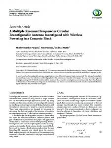
To test the dependence of these resonant frequencies on M and N , the resonant frequencies are calculated as a function of M and N and are plotted in gure 4. This gure clearly shows that M = N � 19 gives stable numerical results and that the rst resonance occurs at f0 = 1:249 GHz and the second resonance occurs at f1 = 1:276 GHz. Microstrip patch resonances are usually associated with the cavity modes described in reference 14. To identify the above two resonances with cavity modes, we must plot a vectorial representation of the surface-current density over the patch that is excited by an incident plane wave at resonant frequencies f0 = 1:249 GHz and f1 = 1:276 GHz, as is done in gures 5(a) and 5(b). These gures show that the magnitude of the surface-current density is proportional to the length of the vector, while the direction of the current ow is indicated by the arrow direction. Upon careful examination of the resonances of the TM01 (transverse magnetic) and TM10 cavity modes given in reference 14, it is clear that the resonance at f0 = 1:249 GHz corresponds to the TM01 mode, and that the resonance at f1 = 1:276 GHz corresponds to the TM10 cavity mode. Note that the cavity model discussed in references 13 and 14 predicts that the resonant frequencies of the TM10 and TM01 modes are identical. This technique, however, gives slightly di�erent resonant frequencies of these modes; this di�erence may be attributed to discretization of the patch. To study higher order resonances of the triangular patch, surface-current densities that are excited by plane waves for the incident angles of (�i = 0�, �i = 0�) and (�i = 0�, �i = 90�) are plotted in gures 6 and 7, respectively, over a wider frequency band. The resonant frequencies of higher order modes of the patch are determined from these gures, and they are presented in table 1 with the corresponding cavity modes calculated using the cavity model (ref. 14) and measured results given in reference 13. The resonant frequencies of the TMmn and TMnm modes are identical, as seen from the cavity model formulations. As noted earlier, the present method that is based on discretization predicts the resonant frequencies of these modes to be slightly di�erent from each other. Corresponding vectorial representations of the surface-current densities at incident angles of (�i = 0�, �i = 0�) and (�i = 0�, �i = 90�) are depicted in gures 8 and 9, respectively, for higher order resonant frequencies. Resonant Frequencies of Circular Patch As a second example, we consider a circular patch with a = 1:88 cm, as shown in gure 10. This patch is assumed to be excited by a parallel polarized plane wave at normal incidence with �i = 0� 7
or �i = 90�. The induced current density ix (p) and iy(p) as a function of frequency at the center of the patch is obtained after solving equation (9), and it is plotted in gures 11(a) and 11(b). Values of M and N were arbitrarily selected to be M = N = 11. These gures show that the frequency at which the real parts of the current densities are maximum and the imaginary parts of the current densities are zero is f0 = 2:760 GHz. The rst resonance of the patch is therefore at 2.760 GHz. To test the dependence of the rst resonance on M and N , f0 is determined as a function of M and N , and it is plotted in gure 12. Figure 12 clearly shows that M = N � 19 gives stable numerical results. This gure also gives the rst resonant frequency of the circular patch obtained using the method described in reference 15. Good agreement exists between the two results for M = N � 19. The vectorial representations of the surface-current density over the circular patch, excited by the x- and y -directed linearly polarized plane waves at the rst resonant frequency, are shown in gures 13(a) and 13(b), respectively. Comparison of this representation with the cavity model representation (ref. 14) indicates that the resonant mode at a frequency of 2.760 GHz corresponds to the TM11 cavity mode. Higher order resonances of the circular patch are determined, and they are given in table 2. This table also gives higher order resonances that are calculated using the cavity model (ref. 14). Good agreement exists between the two methods. A vectorial representation of the surface-current densities at higher order resonant frequencies is given in gure 14. A comparison of these representations with the representations obtained by the cavity model con rms that resonances at frequencies of 4.685 GHz, 5.855 GHz, and 6.360 GHz correspond to the TM21, TM02, and TM31 cavity modes (ref. 14).
Resonant Frequency of Trapezoidal Patch As a third example, we consider a trapezoidal patch with dimensions as shown in gure 15. Figures 16(a) and 16(b) present the variation of current density as a function of frequency at the center of the trapezoidal patch for two angles of incidence. These plots show that the frequency at which the real part of the current density is maximum while the imaginary part is zero is 1.342 GHz. The rst resonance of the patch therefore occurs at a frequency of 1.342 GHz. To test the dependence of the rst resonance on M and N , the rst resonance frequency of the patch is calculated as a function of M and N , and it is given in table 3. Table 3 clearly shows that M � 12 and N � 6 give stable numerical results. Figure 17 gives the vectorial representation of the surface-current density on the patch at the rst resonance for incident angle of (�i = 0�, �i = 0�).
Conclusions An electric- eld integral equation approach in conjunction with the method of moments has been used to determine the resonant frequencies of irregularly shaped microstrip patches. Numerical results obtained using this approach compare well with experimental results and other independent calculations. Discretization of an irregular patch into symmetrical rectangular subdomains, in the present technique, results in a symmetrical and block Toeplitz impedance matrix. The discretization scheme used, however, does not explicitly enforce the proper edge conditions on the surfacecurrent distribution. As a result, a large number of subdomains are required to achieve numerical convergence. NASA Langley Research Center Hampton, VA 23681-0001 August 16, 1993
8
References 1. Carver, Keith R.; and Mink, James W.: Microstrip Antenna Technology.
IEEE Trans. Antennas & Propag.
,
vol. AP-29, no. 1, Jan. 1981, pp. 2{24. 2. Newman, Edward H.; and Tulyathan, Pravit: Analysis of Microstrip Antennas Using Moment Methods.
Trans. Antennas & Propag.
IEEE
, vol. AP-29, no. 1, Jan. 1981, pp. 47{53.
3. Newman, Edward H.; and Forrai, David: Scattering From a Microstrip Patch. vol. AP-35, no. 3, Mar. 1987, pp. 245{251.
IEEE Trans. Antennas & Propag.
,
4. Pozar, David M.: Input Impedance and Mutual Coupling of Rectangular Microstrip Antennas.
Antennas & Propag.
, vol. AP-30, no. 6, Nov. 1982, pp. 1191{1196.
5. Bailey, M. C.; and Deshpande, M. D.: Integral Equation Formulation of Microstrip Antennas.
Antennas & Propag.
IEEE Trans. IEEE Trans.
, vol. AP-30, no. 4, July 1982, pp. 651{656.
6. Bailey, M. C.; and Deshpande, M. D.: Analysis of Elliptical and Circular Microstrip Antennas Using Moment Method.
IEEE Trans. Antennas & Propag.
, vol. AP-33, no. 11, Sept. 1985, pp. 954{959.
7. Newman, Edward H.; and Tulyathan, Pravit: A Surface Patch Model for Polygonal Plates.
& Propag.
IEEETrans.Antennas
, vol. AP-30, no. 4, July 1982, pp. 588{593.
8. Singh, J.; and Adams, A. T.:
Antennas & Propag.
A Nonrectangular Patch Model for Scattering From Surfaces.
, vol. AP-27, July 1979, pp. 531{535.
IEEE Trans.
9. Mosig, Juan R.: Arbitrarily Shaped Microstrip Structures and Their Analysis With a Mixed Potential Integral Equation.
IEEE Trans. Microw. Theory & Tech.
, vol. 36, no. 2, Feb. 1988, pp. 314{323.
10. Michalski, Krzysztof A.; and Zheng, Dalian: Analysis of Microstrip Resonators of Arbitrary Shape.
Microw. Theory & Tech.
IEEE Trans.
, vol. 40, no. 1, Jan. 1992, pp. 112{119.
11. Martinson, Thomas M.; and Kuester, Edward F.: Accurate Analysis of Arbitrarily Shaped Patch Resonators on Thin Substrates.
IEEE Trans. Microw. Theory & Tech.
, vol. 36, no. 2, Feb. 1988, pp. 324{331.
12. Deshpande, Manohar D.; Cockrell, C. R.; Beck, Fred B.; Vedeler, Erik; and Koch, Melissa B.:
Electromagnetic Scattering From Irregularly Shaped, Thin, Metallic Flat Plates
Analysis of
. NASA TP-3361, 1993.
13. Lee, Kai-Fong; Luk, Kwai-Man; and Dahele, Jashwant S.: Characteristics of the Equilateral Triangular Patch Antenna.
IEEE Trans. Antennas & Propag. Microstrip Antennas
, vol. 36, no. 11, Nov. 1988, pp. 1510{1518.
14. Bahl, I. J.; and Bhartia, P.:
. Artech House, Inc., c.1980.
15. Chew, W. C.; and Kong, J. A.: Analysis of a Circular Microstrip Disk Antenna With a Thick Dielectric Substrate.
IEEE Trans. Antennas & Propag.
, vol. AP-29, no. 1, Jan. 1981, pp. 68{76.
9
Table 1. Calculated and Measured Resonant Frequencies of Equilateral Triangular Patch for = = 19
M N
[Patch shown in g. 2] Resonant frequency, GHz Mode
Present method
Measured results (ref. 12)
Cavity model (ref. 13)
TM01
1.249
1.280
1.299
TM10
1.276
TM11
2.172
2.242
2.252
TM02
2.525
2.550
2.599
TM20
2.510
TM12
3.265
TM21
3.356
3.400
3.439
Table 2. Calculated Resonant Frequencies of Higher Order Modes of Circular Patch [Patch shown in g. 10] Resonant frequency, GHz Mode
Present method
Cavity model (ref. 13)
TM11
2.816
2.818
TM21
4.685
4.674
TM02
5.855
5.864
Table 3. Resonant Frequencies of Trapezoidal Patch for Various Values of and
M
N
[Patch shown in g. 15]
M
7 12 14 16 18 20
N
Resonant frequency, GHz 1.370 1.345 1.342 1.343 1.343 1.342
5 6 7 8 9 10
10
z
H i ( E i) E i ( H i) Perpendicular (parallel) polarized plane wave θi
Microstrip patch
εr
d Z'
x y Ground plane (a) Side view of microstrip antenna.
y Patch antenna
(m,n)th subdomain (y-directed current)
N .
φi
. . x n . (m,n)th subdomain (x-directed current)
1 1
2
.
.
m
.
.
.
M
Wx (b) Top view of microstrip antenna. Figure 1. Geometry of microstrip antenna.
11
Wy
y
N+1
Wx
Wy
1 2
3 4 5
x
1 2
3
M+1
4 5
a Figure 2. Geometry of equilateral triangular patch with dimen sions a = 10 cm,
"r
:
:
= 2 32, and loss tangent = 0 002.
12
d = z0
:
= 0 16 cm,
5.0
i x ( 25 )/ E i , A/unit area
Real part Imaginary part 2.5
0.0
-2.5
-5.0 1.000
1.050
1.100
1.150
1.200
1.250
1.300
1.350
1.250
1.300
1.350
Resonant frequency, GHz
15
Real part Imaginary part
i y ( 67 ) / E i , A/unit area
10
5
0
-5
-10
f0 -15 1.000
1.050
1.100
1.150
1.200
Resonant frequency, GHz
(a) (�i = 0�, �i = 90�); f0 = 1:210 GHz. Figure 3. Normalized current density as function of resonant frequency for equilateral triangular patch (shown in g. 2) for angles of incidence of (�i = 0�, �i = 90�) and (�i = 0�, �i = 0�), M = N = 11, f0 = 1:210 GHz, and f1 = 1:256 GHz.
13
i x ( 25 )/ E i , A/unit area
15 10
Real part Imaginary part
5 0 -5
f1
-10 -15 1.000
1.050
1.100
1.150
1.200
1.250
1.300
1.350
1.250
1.300
1.350
Resonant frequency, GHz
5.0
i y ( 67 ) / E i , A/unit area
Real part Imaginary part 2.5
0.0
-2.5
-5.0 1.000
1.050
1.100
1.150
1.200
Resonant frequency, GHz (b) (�i = 0�, �i = 0� ); f1 = 1:256 GHz. Figure 3. Concluded.
14
f 0 , GHz
1.350
1.300
1.250
1.200 11
12
13
14
15
16
17
18
19
20
21
22
23
19
20
21
22
23
M=N
(a) Variation of
f0.
f 1, GHz
1.350
1.300
1.250
1.200 11
12
13
14
15
16
17
18
M=N
(b) Variation of
f 1.
Figure 4. First two resonant frequencies of equilateral triangular patch (shown in g. 2) for
15
M = N.
(a) (�i = 0�, �i = 90�); f0 = 1:249 GHz (TM01 mode case). Figure 5. Vectorial representation of surface-current density on equilateral triangular patch (shown in g. 2) excited by plane wave with angles of incidence of (�i = 0�, �i = 90�) and (�i = 0�, �i = 0�), f0 = 1:249 GHz (TM01 mode case), and f1 = 1:276 GHz (TM10 mode case).
16
(b) (�i = 0�, �i = 0�); f1 = 1:276 GHz (TM10 mode case). Figure 5. Concluded.
17
1.0
i x ( 57 )/ E i , A/unit area
Real part Imaginary part 0.5
f6 0.0
-0.5
-1.0 1.0
f1
f3
1.5
2.0
2.5
3.0
3.5
4.0
3.5
4.0
Resonant frequency, GHz
1.0
i y ( 226 ) / E i , A/unit area
Real part Imaginary part 0.5
0.0
-0.5
-1.0 1.0
1.5
2.0
2.5
3.0
Resonant frequency, GHz
Figure 6. Normalized current density as function of resonant frequency for equilateral triangular patch (shown in g. 2) excited by plane wave at angle of incidence of (�i = 0�, �i = 0�) and M = N = 19. The terms f1 (1.276 GHz), f3 (2.510 GHz), and f6 (3.355 GHz) are resonant frequencies of TM10, TM20, and TM21 modes, respectively.
18
1.0
i x ( 57 )/ Ei , A/unit area
Real part Imaginary part 0.5
0.0
-0.5
-1.0 1.0
1.5
2.0
2.5
3.0
3.5
4.0
Resonant frequency, GHz
1.0
i y ( 226 ) / E i , A/unit area
Real part Imaginary part
f4
0.5
Higher mode
0.0
-0.5
f0
f2 f5
-1.0 1.0
1.5
2.0
2.5
3.0
3.5
4.0
Resonant frequency, GHz
Figure 7. Normalized current density as function of resonant frequency for equilateral triangular patch (shown in g. 2) excited by plane wave at angle of incidence of (�i = 0�, �i = 90�) and M = N = 19. The terms f0 (1.249 GHz), f2 (2.172 GHz), f4 (2.525 GHz), and f5 (3.265 GHz) are resonant frequencies of TM01, TM11, TM02, and TM12 modes, respectively.
19
(a) f2 = 2:172 GHz (TM11 mode case). Figure 8. Vectorial representation of surface-current density on equilateral triangular patch (shown in g. 2) excited by plane wave with angle of incidence of (�i = 0�, �i = 0�) and resonant frequencies f2 = 2:172 GHz (TM11 mode case), f4 = 2:510 GHz (TM20 mode case), and f5 = 3:355 GHz (TM21 mode case).
20
(b)
f
4 = 2:510 GHz (TM20 mode case). Figure 8. Continued.
21
(c)
5 = 3:355 GHz (TM21 mode case).
f
Figure 8. Concluded.
22
(a) f2 = 2:172 GHz (TM11 mode case). Figure 9. Vectorial representation of surface-current density on equilateral triangular patch (shown in g. 2) excited by plane wave with angle of incidence of (�i = 0�, �i = 90�) and resonant frequencies f2 = 2:172 GHz (TM11 mode case), f4 = 2:510 GHz (TM02 mode case), and f5 = 3:265 GHz (TM12 mode case).
23
(b)
f
4 = 2:510 GHz (TM02 mode case). Figure 9. Continued.
24
(c)
5 = 3:265 GHz (TM12 mode case).
f
Figure 9. Concluded.
25
y
N+1
Wx
a
x
1 2
3
4
5
Wy
1
2
3 4
5
M+1 :
Figure 10. Geometry of circular patch with radius a = 1 88 cm,
:
Loss tangent = 0 002.
26
d = z0
:
= 0 16 cm,
"r
:
= 2 53, and
2.0
i x ( 43 )/ E i , A/unit area
1.5
Real part Imaginary part
1.0 0.5 0.0 -0.5 -1.0
f0
-1.5 -2.0 2.00
0 2.25
2.50
2.75
3.00
2.75
3.00
Resonant frequency, GHz
2.0
i y ( 120 ) / E i , A/unit area
1.5
Real part Imaginary part
1.0 0.5 0.0 -0.5 -1.0 -1.5 -2.0 2.00
2.25
2.50
Resonant frequency, GHz
(a) (�i = 0�, �i = 0�). Figure 11. Normalized current density as function of resonant frequency for circular patch (shown in g. 10) for angles of incidence of (�i = 0�, �i = 0�) and (�i = 0�, �i = 90�), M = N = 11, and f0 = 2:76 GHz.
27
2.0
i x ( 43 )/ Ei , A/unit area
1.5
Real part Imaginary part
1.0 0.5 0.0 -0.5 -1.0 -1.5 -2.0 2.00
2.25
2.50
2.75
3.00
Resonant frequency, GHz
2.0
i y ( 120 ) / E i , A/unit area
1.5
Real part Imaginary part
1.0 0.5 0.0 -0.5 -1.0
f0 -1.5 -2.0 2.00
2.25
2.50
Resonant frequency, GHz (b) (� i = 0�, �i = 90� ). Figure 11. Concluded.
28
2.75
3.00
3 .0 0
Resonant frequency of TM11 mode, GHz
2 .9 0
Result from reference 14
2 .8 0
Present method 2 .7 0
2 .6 0
2 .5 0 11
12
13
14
15
16
17
18
19
20
21
22
23
M=N
Figure 12. Resonant frequency of circular patch TM11 mode (shown in g. 10), excited by plane wave at angle of incidence of (�i = 0�, �i = 0�) as function of M = N .
29
(a) (�i = 0�, �i = 0�). Figure 13. Vectorial representation of surface-current density on circular patch (shown in g. 10) excited by plane wave with angles of incidence of (�i = 0�, �i = 0�) and (�i = 0�, �i = 90�) and f0 = 2:796 GHz (TM11 mode case).
30
(b) (� i = 0�, �i = 90� ). Figure 13. Concluded.
31
(a) f1 = 4:685 GHz (TM21 mode case). Figure 14. Vectorial representation of surface-current density on circular patch (shown in g. 10) excited by plane wave with angle of incidence of (�i = 45�, �i = 90�) and resonant frequencies f1 = 4:685 GHz (TM21 mode case), f2 = 5:855 GHz (TM02 mode case), and f3 = 6:360 GHz (TM31 mode case).
32
(b)
f
2 = 5:855 GHz (TM02 mode case). Figure 14. Continued.
33
(c)
3 = 6:360 GHz (TM31 mode case).
f
Figure 14. Concluded.
34
y
N+1
b
c x
3 2 1 1
2
3
4
M+1
a
:
Figure 15. Geometry of trapezoidal patch with radius a = 8 08 cm,
� = 45, "r = 2:65, and Loss tangent = 0:002.
35
b = c = 4:04 cm, d = z
0
:
= 0 16 cm,
5.0
i x ( 70 )/ E i , A/unit area
Real part Imaginary part 2.5
0.0
-2.5
-5.0 1.00
f0 1.25
1.50
1.75
2.00
Resonant frequency, GHz
2.0
Real part Imaginary part
i y ( 205 ) / E i , A/unit area
1.5 1.0 0.5 0.0 -0.5 -1.0 -1.5 -2.0 1.00
1.25
1.50
1.75
2.00
Resonant frequency, GHz
(a) (�i = 45�, �i = 0�). Figure 16. Normalized current density as function of resonant frequency for trapezoidal patch (shown in g. 15) excited by plane wave at angles of incidence of (�i = 45�, �i = 0�) and (�i = 45�, �i = 90�), M = 20, and N = 10.
36
2.0
Real part Imaginary part
i x ( 70 )/ E i , A/unit area
1.5 1.0 0.5 0.0 -0.5 -1.0 -1.5 -2.0 1.00
f0 1.25
1.50
1.75
2.00
Resonant frequency, GHz
2.0
Real part Imaginary part
i y ( 205 ) / E i , A/unit area
1.5 1.0 0.5 0.0 -0.5 -1.0 -1.5 -2.0 1.00
1.25
1.50
Resonant frequency, GHz (b) (� i = 45�, �i = 90� ). Figure 16. Concluded.
37
1.75
2.00
Figure 17. Vectorial representation of surface-current density on trapezoidal patch (shown in g. 15) excited by plane wave with angle of incidence of (�i = 0�, �i = 0�), f0 = 1:345 GHz, M = 20, and N = 10.
38
REPORT DOCUMENTATION PAGE
Form Approved OMB No. 0704-0188
Public reporting burden for this collection of information is estimated to average 1 hour per response, including the time for reviewing instructions, searching existing data sources, gathering and maintaining the data needed, and completing and reviewing the collection of information. Send comments regarding this burden estimate or any other aspect of this collection of information, including suggestions for reducing this burden, to Washington Headquarters Services, Directorate for Information Operations and Reports, 1215 Je�erson Davis Highway, Suite 1204, Arlington, VA 22202-4302, and to the O�ce of Management and Budget, Paperwork Reduction Project (0704-0188), Washington, DC 20503. 1. AGENCY USE ONLY(Leave blank)
2. REPORT DATE
October 1993
3. REPORT TYPE AND DATES COVERED
Technical Paper
4. TITLE AND SUBTITLE
Resonant Frequencies of Irregularly Shaped Microstrip Antennas Using Method of Moments
5. FUNDING NUMBERS
WU 505-64-70-01 PR 1L162211AH85
6. AUTHOR(S)
Manohar D. Deshpande, David G. Shively, and C. R. Cockrell
7. PERFORMING ORGANIZATION NAME(S) AND ADDRESS(ES)
NASA Langley Research Center Hampton, VA 23681-0001
Joint Research Program O�ce Electronics Integration Directorate Communications Electronics Command Langley Research Center Hampton, VA 23681-0001
9. SPONSORING/MONITORING AGENCY NAME(S) AND ADDRESS(ES)
8. PERFORMING ORGANIZATION REPORT NUMBER
L-17160
10. SPONSORING/MONITORING AGENCY REPORT NUMBER
National Aeronautics and Space Administration Washington, DC 20546-0001 and U.S. Army Communications Electronics Command Fort Monmouth, NJ 07703-5603
NASA TP-3386 CECOM TR-93-E-1
11. SUPPLEMENTARY NOTES
Deshpande: ViGYAN, Inc., Hampton, VA; Shively: Joint Research Program O�ce, EID-CECOM, Langley Research Center, Hampton, VA; Cockrell: Langley Research Center, Hampton, VA. 12a. DISTRIBUTION/AVAILABILITY STATEMENT
12b. DISTRIBUTION CODE
Unclassi ed{Unlimited Subject Category 32 13. ABSTRACT (Maximum 200 words)
This paper describes an application of the method of moments to determine resonant frequencies of irregularly shaped microstrip patches embedded in a grounded dielectric slab. For analysis, the microstrip patch is assumed to be excited by a linearly polarized plane wave that is normal to the patch. The surface-current density that is induced on the patch because of the incident eld is expressed in terms of subdomain functions by dividing the patch into identical rectangular subdomains. The amplitudes of the subdomain functions, as a function of frequency, are determined using the electric- eld integral equation (EFIE) approach in conjunction with the method of moments. The resonant frequencies of the patch are then obtained by selecting the frequency at which the amplitude of the surface-current density is real. The resonant frequencies of the equilateral triangular and other nonrectangular patches are computed using the present technique, and these frequencies are compared with measurements and other independent calculations.
14. SUBJECT TERMS
Antennas; Microstrip; Resonant frequency; Method of moments
15. NUMBER OF PAGES
39
16. PRICE CODE
A03
17. SECURITY CLASSIFICATION OF REPORT
Unclassi ed
NSN 7540 -01-280-55 00
18. SECURITY CLASSIFICATION 19. SECURITY CLASSIFICATION 20. LIMITATION OF THIS PAGE OF ABSTRACT OF ABSTRACT
Unclassi ed
Unclassi ed
Standard Form 298(Rev. 2-89)
Prescribed by ANSI Std. Z39-18 298-102