arXiv:cond-mat/0505510v1 [cond-mat.mes-hall] 20 May 2005. Resonant three-dimensional ... Yablonovich1 and John2 in 1987. Since then this term is used for ...
Resonant three-dimensional photonic crystals E.L. Ivchenko and A.N. Poddubny
arXiv:cond-mat/0505510v1 [cond-mat.mes-hall] 20 May 2005
A.F. Ioffe Physico-Technical Institute, Russian Academy of Sciences, St. Petersburg 194021, Russia We have developed a theory of exciton-polariton band structure of resonant three-dimensional photonic crystals for arbitrary dielectric contrast and effective mass of the exciton that is excited in one of the compositional materials. The calculation has been carried out for a periodic array of spheres embedded in a dielectric matrix. It has been shown that the position of the lower branches of the polariton dispersion curve monotonously depends on the exciton effective mass and is determined by the coupling of light with the first few states of the mechanical exciton quantum confined inside each sphere. Particularly, we have studied the role of excitonic effects on the photonic-crystal band gap along the [001] direction of the Brillouin zone and presented an analytic description of the polariton dispersion in terms of the two-wave approximation. PACS numbers: 71.35.-y, 71.36.+c, 42.70.Qs
1.
INTRODUCTION
The concept of photonic crystals was put forward by Yablonovich1 and John2 in 1987. Since then this term is used for media with the dielectric susceptibility varying periodically in the space and allowing the Bragg diffraction of the light. The theory of photonic crystals has been developed in a number of subsequent works, see, e.g., Refs. 3,4,5,6,7. The main goal of these studies was to determine the photon band structure and analyze the sequence of allowed bands and stop-bands (gaps) for different directions of the wave vector in the first Brillouin zone. The simplest model realization of a photonic crystal is a structure grown from two materials, A and B, with different dielectric constants εA and εB : a periodic layered medium ...A/B/A/B... in case of one-dimensional photonic crystals and periodic arrays of cylinders and spheres of the material A embedded in a dielectric matrix B, in case of two-dimensional and three-dimensional photonic crystals, respectively. Periodic structures where the dielectric susceptibility of one of the compositional materials, as a function of the frequency ω, has a pole at a certain resonance frequency are grouped into a special class of resonant photonic crystals. In such systems the normal light waves are excitonic polaritons. In Refs. 8,9 the dispersion of light waves has been calculated taking into consideration the frequency dependence of the dielectric susceptibility in the frame of the local material relation D = εA (ω)E between the electric displacement and the electric field. In Ref. 10 the dispersion of excitonic polaritons in a resonant photonic crystal has been calculated taking into account only one level of the quantum-confined exciton in a sphere A and neglecting the difference between the dielectric constant εB and the background dielectric constant εa of the material A. In the present work we have studied theoretically the dispersion of excitonic polaritons in a resonant photonic crystal making allowance for all available exciton quantumconfinement levels as well as for the dielectric contrast, i.e., for εa 6= εB .
2.
PROBLEM DEFINITION AND METHOD OF CALCULATION
In this work the theory of resonant photonic crystals is developed for a periodic array of spheres A arranged in a face-centered cubic (FCC) lattice and embedded in the matrix B. The structure under consideration is characterized by seven parameters: R, a, εB , εa , ωLT , ω0 and M . Here R is the radius of the spheres A, a is the lattice constant for the FCC lattice, εB is the dielectric constant of the matrix, ω0 , ωLT and M are the resonance frequency, longitudinal-transverse splitting and translational effective mass of the triplet 1s exciton excited inside the spheres A, εa is the background dielectric constant that contains contributions to the dielectric response from all other electron-hole excitations. Thus, we assume the dielectric function of the bulk material A to have the form εa ωLT ¯hq 2 εA (ω, q) = εa + , ωexc (q) = ω0 + (1) ωexc(q) − ω 2M and, in that way, take into account both the frequency and spatial dispersion, i.e. the dependence on the light frequency ω and wave vector q. The radius R is chosen so that, on the √ one hand, the spheres A do not overlap, i.e. R < a/2 2, but, on the other hand, R should exceed the Bohr radius of the 1s-exciton in the material A and, hence, the exciton can be considered as a single particle with the mass M . In the following we ignore the frequency dependence of the parameters εB and εa . Moreover, hereafter we assume the material A to be isotropic and take into consideration the bulk 1s exciton states only. It follows then that the problem is reduced to the solution of a system of two vector equations, namely, the wave equation � ω �2 � � ε(r)E(r) + 4πPexc (r) (2) rot rot E(r) = c and the material equation for the 1s-exciton contribution to the dielectric polarization � � εa ωLT ¯h ∆ + ω0 − ω Pexc (r) = E(r) , (3) − 2M 4π
2 where ε(r) = εa inside the spheres and ε(r) = εB outside the spheres, E(r) and Pexc (r) are the electric field and the excitonic polarization at the frequency ω. On a spherical surface separating materials A and B we impose the standard Maxwell boundary conditions: continuity of the tangential components of the electric and magnetic fields, and the Pekar additional boundary condition for the excitonic polarization: the vanishing vector Pexc (r) at |r − a| = R, where the translational vectors a define the centers of spheres A. Due to the periodicity of the structure we can seek solutions of Eqs. (2) and (3) in the Bloch form satisfying the condition Ek (r + a) = eika Ek (r) .
(4)
Here k is the exciton-polariton wave vector defined within the first Brillouin zone. We remind that, for a FCC lattice, the latter is a dodecahedron bounded by six squares and eight hexagons. Below we present the results of calculation of the exciton-polariton dispersion ωnk , where n is the branch index. The computation was mainly performed by using a photon analogue of the Korringa-Kohn-Rostoker (KKR) method11,12,13 . In this method (i) the electric field is decomposed in the spherical waves, or more precisely, in the vector spherical functions centered at the points r = a, and (ii) following the consideration of the light scattering by a single sphere and the introduction of a structural factor the dispersion equation is transformed to |δj ′ j δm′ m δσ′ σ − Gj ′ m′ σ′ ,jmσ (k, ω)Rjσ (ω)| = 0 .
(5)
Here Rjσ are the coefficients describing the scattering of spherical waves by a single sphere A, they depend on the total angular momentum j and the polarization index σ discriminating the magnetic and electric spherical harmonics but are independent of the angular-momentum component m. Note that, for a spherical scatterer, these coefficients relate the incident field E0 (r) ∝ Jjmσ (r) with the scattered field Esc (r) ∝ Hjmσ (r), where Jjmσ , Hjmσ are the vector spherical functions13 . Ajiki et al.14 have calculated values of Rjσ (ω) taking into account the exciton resonance in the spheres A and the finite exciton effective mass M . In contrast to the scattering matrix for a single sphere which is diagonal, Rj ′ m′ σ′ ,jmσ ≡ Rjσ δj ′ m′ σ′ ,jmσ , the matrix of structural factors Gj ′ m′ σ′ ,jmσ (k, ω) has nonvanishing diagonal and off-diagonal components. It should be mentioned that the both matrices are frequency dependent whereas only the structural matrix G depends upon the polariton wave vector k. At the same time G is independent of the excitonic parameters and coincides with the matrix considered in Refs. 11,12,13 where the exciton states are disregarded. In addition to the KKR method, in section 4 we apply the Green-function technique for the analysis of separate contributions of quantum-confined excitonic levels to the
0
(ω-ω1)/ωLT
-1
-2
-3
-4
-5
X
L
U
Λ
Γ
∆
X
Z W
K
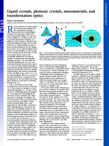
FIG. 1: Exciton-polariton band structure of a photonic crystal with a FCC lattice of spheres A inserted into the matrix B. The calculation is performed neglecting the dielectric contrast and for the set of parameters indicated in the text.
polariton dispersion, and in section 5 we use the two-wave approximation which allows an analytic description. 3.
POLARITON DISPERSION FOR A FINITE EXCITON MASS
First we focus the attention upon purely excitonic effects and neglect the dielectric contrast assuming εa = εB . Then in the absence of exciton-photon interaction, i.e. for ωLT = 0, the medium becomes optically homogeneous and photons propagating therein are characterized by the linear dispersion ω = cq/nB with the refractive in√ dex nB = εB . In the reduced zone scheme, this singlevalued relation between the frequency and wave vector q turns into the many-valued (or multi-branch) dispersion curve ωk = c|k + b|/nB ,
(6)
where b is the reciprocal lattice vector reducing q to the vector k = q − b that lies in the first Brillouin zone. A nonvanishing value of ωLT leads to a mixing between photonic and excitonic states and formation of hybrid polariton excitations characterized by a complicated multiband dispersion ωnk . As a result the wave (n, k) is a mixture of two or more photonic states (6) with the same k but different b. Fig. 1 presents the dispersion of exciton-polaritons calculated for a FCC lattice and the following set of structure parameters: εa = εB = 10 , R = a/4 , ¯hω1 = 2 eV , ωLT = 5 × 10⁻⁴ ω1 ,
P ≡
√
3πc ω 1 nB a
!3
= 1.1 , M = 0.5 m0 .
Here m0 is the free electron mass in vacuum and, instead
3 of the bulk exciton resonance frequency ω0 , we introduced the resonance frequency
0
0.0
(7)
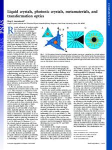
of the ground state of the exciton quantum-confined in a sphere of the radius R. Note that, for the structure tuned to the Bragg resonance ω1 √ = ckL /nb at the point L of the Brillouin zone with kL = 3π/a or ω1 = ckX /nb at the point√X with kX = 2π/a, the parameter P equals to 1 and 3 3/8 ≈ 0.65, respectively. For P = 1.1, the anticrossing between the horizontal line ω = ω1 (“bare” exciton branch) and the line ω = ck/nB (“bare” photon branch) occurs inside the Brillouin zone at k amounting approximately 97% of kL and 84% of kX . For the sake of completeness the dependence ω(k) is shown not only along the high-symmetry crystallographic directions k k [001] (points ∆) and k k [111] (points Λ) but also along the straight lines X − W , W − K, X − U and U − L. In Fig. 1 the frequency region is cut from above in order to keep only few branches of the dispersion curve. In the cut region the dispersion is presented by a dense network of polariton branches which appear as a result of the anticrossing of “bare” photonic branches (6) with a set of close-lying exciton quantum-confinement levels. The network has a tangled character complicated for depiction. Therefore, we concentrate here on the analysis of the role played by the photonic-crystal parameters in the formation of the lower polariton branches. In Fig. 2 the solid curves show the same dispersion branches as in the previous figure but in an increased scale and in the vicinity of the points X and L. For comparison we also present, by dashed-and-dotted lines, the lower branch of the dispersion curve calculated taking into account only the ground exciton quantumconfinement level. The calculation was performed by reducing the value of M to 0.01m0 and decreasing ω0 so that the frequency ω1 in Eq. (7) was kept invariant. The dashed-and-dotted lines coincide with those calculated by the method proposed for exciton-polaritons in Ref. 10. Dashed curves illustrate the opposite limiting case of quite heavy excitons, M → ∞. In this case the relation between the exciton polarization and electric field becomes local: εa ωLT Pexc = χE , χ= . 4π ω0 − ω It means that values of k corresponding to a certain frequency ω can be found in the same way as it is done for nonresonant photonic crystal with the dielectric susceptibilities εB and εA = εa + 4πχ. The calculation shows that the dashed line in Fig. 2 is practically indistinguishable from the lower branch obtained according to Eq. (5) for M = 5m0 . The lower polariton branch is formed as a result of “repulsion” of the photon branch (6) with b = 0 towards the long-wavelength side because of the interaction with the exciton quantum-confinement levels. For
-1
-0.5
-2
(ω-ω1)/ωLT
¯ � π �2 h ω1 = ω0 + 2M R
M → 0 but ω1 = const, this branch is remarkably affected by the lower level (7) only. For M → ∞, the
-3 -1.0 -4 -1.5 -5
-6
L
Λ 1/2
0.2 x 3 π/a
∆
X
-2.0
0.4 x 2π/a
FIG. 2: Dispersion of exciton polaritons in a resonant photonic crystal in the spectral region adjoining the resonance frequency of the lower exciton level ω1 and for the wave vectors k k [111] (points Λ) and k k [001] (points ∆). The dispersion curves are calculated for the exciton effective mass M = 0.5 m0 (solid lines), M → ∞ (dashed lines) and M → 0 (dashed-and-dotted lines). Other parameters are the same as in Fig. 1.
other levels act upon this branch to the maximum since in this limit their resonance frequencies coincide and are equal to ω0 . We conclude then that the lower polariton branch corresponding to the finite mass M must always lie between the dashed-and-dotted and dashed lines, in agreement with the results of calculation shown in Fig. 2.
4. COMPARATIVE CONTRIBUTION OF INDIVIDUAL QUANTUM-CONFINED EXCITON LEVELS
In the following we use the notation ωX (M ) for the frequency at the X point in the lowest polariton branch for the exciton effective mass M in the material A, ωX (0) and ωX (∞) for values of this frequency for M → 0 and M → ∞, and, finally, ω ¯ X for the arithmetic mean [ωX (0) + ωX (∞)]/2. One can see from Fig. 2 that the difference ω1 − ω ¯ X noticeably exceeds the difference ωX (0) − ωX (∞). This means that the main contribution to the position of the frequency ωX (M ) should come from the exciton-photon coupling with the ground level (7). In this section we analyze in detail the influence of the ground and excited levels of the quantum-confined exciton on the lower polariton branch. To this end we follow Ref. 14, use the Green-function technique and expand a solution of equation (3) with arbitrary function E(r) in a series
4
Pexc (r) =
εa X ωLT X Φν (r − a) 4π ν ων − ω a
Z
Φ∗ν (r ′ − a)E(r ′ )d3 r′
(8)
|r ′ −a| ω0 . It is not shown in the figure in order to avoid overloading the image. Instead, only the exciton-polariton eigen frequencies ων > ω0 at the X point are indicated by short horizontal lines intersecting the vertical line X. In what follows we propose a two-wave approximate description of the polariton spectrum which is valid for a weak dielectric contrast and allows to understand the nature of branches indicated in Fig. 4 by primed and double-primed integers. Earlier this approximation was used in the analysis of the photon dispersion in nonresonant photonic crystals16. The Bloch solution (4) can be expanded over the space harmonics with the wave vectors k + b. For the vec-
5 �
20
3′
2 10
(ω-ω1)/ωLT
2′
X X � Ej Iν(2)∗ Iν(j) Tν . (k2 /k0 )2 − ε¯ E2 = ε′ E1 + j=1,2
ν
The notation used are as follows: k0 = ω/c, 4′
0
ε¯ =
2′′ -10
1 v0
Z
ε(r)d3 r , ε′ =
v0
1 v0
Z
e4πiz/a ε(r)d3 r ,
v0
1 1′
-20
1′′ ∆
X
Iν(j)
Z
0.017 x 2π/a
0.1 x π/a
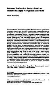
FIG. 4: Photon band structure for a crystal with the dielectric contrast, εa = 12, εB = 13. Dashed lines are calculated for a photonic crystal neglecting excitons; solid lines are obtained taking into account only the lowest excitonic level; dashedand-dotted lines and short straight lines are obtained taking into account all quantum-confined states of the mechanical exciton.
tors k k [001] lying close to the X point, we keep in this expansion only two terms with k1 = (0, 0, k1 ), k2 = (0, 0, k2 ) and k1 − k2 = 4π/a. At the X point we have k1 = −k2 = 2π/a. Thus, the electric field is approximated by E(r) = E1 eik1 z + E2 eik2 z .
(9)
For doubly-degenerate polariton states of the ∆5 symmetry compatible with the representations X5 and X5′ , the amplitudes E1 and E2 are parallel to each other and perpendicular to the axis z k [001]. Substituting Eqs. (8) and (9) into the wave equation (2), multiplying its terms by exp (−ikj z) and integrating over the unit primitive cell v0 = a3 /4 of the FCC lattice we obtain X X � � Ej Iν(1)∗ Iν(j) Tν ,(10) (k1 /k0 )2 − ε¯ E1 = ε′ E2 + j=1,2
1 = √ v0
Z
eikj z Φ∗ν (r)d3 r , Tν =
v0
εa ωLT , ων − ω
(11)
and we assume the origin of the Cartesian coordinate system to be chosen in the center of one of the spheres A. In the absence of the exciton-photon coupling and dielectric contrast, the right-hand sides of equations (10) vanish, ε¯ = εB , and we arrive at two branches of the dispersion relation (6) for “bare” photons. At the X point these branches converge. In the presence of dielectric contrast, ε′ 6= 0 and the fourfold degenerate state at the X point splits into doubly-degenerate states X5′ (E1 = E2 ) and X5 (E1 = −E2 ) with their eigen frequencies being ckX ckX ω(X5 ) = √ , ω(X5′ ) = √ ′ ε¯ − ε ε¯ + ε′
(12)
′ ε)(ckX /¯ n), and the splitting being ω(X √ 5 ) − ω(X5′ ) ≈ (ε /¯ where kX = 2π/a, n ¯ = ε¯. The approximate equations (12) reproduce with high accuracy results of the exact calculation presented in Fig. 4 by dashed lines. In the absence of dielectric contrast, with allowance for the exciton level 1s only and negligible difference be(2) (1) tween the integrals I1s and I1s the set of equations (10) reduces to
ν
� � � � 2 (E1 + E2 ) , (k1 /k0 )2 − εB E1 = (k2 /k0 )2 − εB E2 = T1s I1s where I1s is the integral (11) corresponding to the wave vector kX . Provided that the frequencies ω1 and ωX ≡ ckX /nB are close to each other, the photonic states X5 , X5′ are replaced by three doubly-degenerate polaritonic states: one of the symmetry X5 with the frequency ωX and two of the symmetry X5′ with the frequencies s� �2 ω1 + ωX ω1 − ωX + δ2 , (14) ± ω= 2 2 p 2 . For coinciding frequencies ω where δ = ω1 ωLT I1s 1 and ωX , the polariton spectrum in the direction k k [001]
(13)
has a stop-band of the width 2δ centered at ω = ω1 . The detuning of ωX from ω1 leads to shifts of the stop-band edges according to Eq. (13) and, in addition, an allowed band is formed in the center of the stop-band, similarly as it happens in the resonant Bragg quantum-well structure (see17 and references therein). For an approximate description of the solid lines in Fig. 4 it suffices to keep in the sums over ν in Eqs. (10) only the contribution due to the exciton quantumconfined ground state. In this approximation the mixing of the photon and exciton states of the symmetry X5′
6 leads to their repulsion and formation of hybrid waves with the frequencies s� �2 ω1 + ω(X5′ ) ω1 − ω(X5′ ) ω= + δ2 . (15) ± 2 2 The previous equation (14) is a particular case of this more general equation. Since the 1s quantum-confined exciton does not interact with the light wave of the symmetry X5 , the X5 photon frequency remains unchanged in the considered approximation. This allows to understand the closeness of the X5 -polariton frequencies calculated neglecting the exciton effects and taking into account only the 1s level, see the points of intersection of the lines 2 and 2′ with the vertical line X. Allowance for the excited excitonic levels in Eq. (10) results in a shift of the frequency of the lowest polariton branch X5′ downwards (line 1′′ ). However, their influence is small in comparison with the 1s exciton. At the same time, in the formation of the polariton X5 (line 2′′ ) the main role is played by coupling of the photon X5 with the exciton 1p and m = 0. The calculation shows that the branch 2′′ is well described by the two-wave model (10) taking into account only one excitonic state (1p, m = 0). 6.
CONCLUSION
We have developed a theory of resonant threedimensional photonic crystals made up of two compositional materials A (spheres) and B (dielectric matrix) for an arbitrary value of the exciton effective mass M and arbitrary dielectric contrast determined by the difference between the dielectric susceptibility εB of the matrix and the background dielectric constant εa of the material A.
1 2 3
4
5
6 7 8 9
10
E. Yablonovitch, Phys. Rev. Lett. 58, 2059 (1987). S. John, Phys. Rev. Lett. 58, 2486 (1987). K.M. Ho, C.T. Chan, and C.M. Soukoulis, Phys. Rev. Lett. 65, 3152 (1990). R.D. Meade, A.M. Rappe, K.D. Brommer, J.D. Joannopoulos, and O.L. Alerhand, Phys. Rev. B 48, 8434 (1993). R. M. Hornreich, S. Shtrikman, and C. Sommers, Phys. Rev. B 49, 10914 (1994). J. E. Sipe, Phys. Rev. E 62, 5672 (2000). K. Busch, C. R. Physique 3, 53 (2002). O. Toader and S. John, Phys. Rev. E 70, 46605 (2004). K.C. Huang, E. Lidorikis, X. Jiang, J.D. Joannopoulos, K.A. Nelson, P. Bienstman, and S. Fan, Phys. Rev. B 69, 195111 (2004). E.L. Ivchenko, Y. Fu, and M. Willander, Fiz. Tverd. Tela 42, 1705 (2000) [Phys. Solid State 42, 1756 (2000)].
For a finite value of M , the lowest polariton branch lies between the branches calculated in the two limiting cases, namely, in the absence of space dispersion, i.e., for M → ∞, and with allowance for only one excitonic level, i.e., for M → 0 and ω1 = const. For a satisfactory description of the polariton branches in the frequency region ω < ω1 , it suffices to take into account the light coupling with few lowest states of the mechanical exciton. For a resonant photonic crystal with the dielectric contrast, we have analyzed the exciton-induced modification of the stop-band in the [001] direction if the exciton resonance frequency ω1 is chosen to lie in the middle of the stop-band of the analogous photonic crystal without excitons. If the dielectric contrast is weak so that |εB − εa | ≪ εB then one can use the two-wave approximation that allows describe with good accuracy the results of numerical calculation. The main contribution into the position of the lower edge of the polariton stopband along the Γ − X line comes from the exciton 1s states interacting with the light wave of the X5′ symmetry. The upper edge of the stop-band is governed by the coupling of the exciton (1p, m = 0) with the photon of the X5 symmetry. It should be noted that the developed theory with M → ∞ can be applied for the study of photonic crystals infiltrated with dye aggregates periodically distributed in the space and characterized by a certain resonance frequency of optical transitions, see18 and references therein. The theory can be applied as well for the calculation of the dispersion of exciton-polaritons in resonant two-dimensional photonic crystals, e.g., in periodic arrays of cylinders A embedded into the matrix B. The work is supported by the Russian Foundation for Basic Research (grant 05-02-16372) and the program of the Russian Ministry of Science and Education.
11 12 13
14
15
16
17
18
A. Moroz, Phys. Rev. B 51, 2068 (1995). A. Moroz, Phys. Rev. B 66, 115109 (2002). X. Wang, X.-G. Zhang, Q. Yu, and B.N. Harmon, Phys. Rev. B 47, 4161 (1993). H. Ajiki, T. Tsuji, K. Kawano, and K. Cho, Phys. Rev. B 66, 245322 (2002). S. Fl¨ ugge, Practical quantum mechanics I, SpringerVerlag, Berlin – Heidelberg – New-York, 1971. S. Satpathy, Ze Zhang, and M.R. Salehpour, Phys. Rev. Lett. 64, 1239 (1990). E.L. Ivchenko, M.M. Voronov, M.V. Erementchouk, L.I. Deych, and A.A. Lisyansky, Phys. Rev. B70, 195106 (2004). N. Eradat, A.Y. Sivachenko, M.E. Raikh, Z.V. Vardeny A.A. Zakhidov, and R.H. Baughman, Appl. Phys. Lett. 80, 3491 (2002).