1
Resource Allocation in Topology Management of Asymmetric Interference Networks Xinyu Zhang, Student Member, IEEE, Nan Zhao, Senior Member, IEEE, F. Richard Yu, Senior Member, IEEE, Minglu Jin, Member, IEEE, and Victor C.M. Leung, Fellow, IEEE
Abstract—Most existing works of interference alignment focus on symmetric networks. When the difference of path loss is considered in asymmetric networks, topology management needs to be carefully designed for interference alignment based interference networks. Using topology management, the network is separated into an interference alignment subnetwork and some spatial multiplexing subnetworks. In this paper, antenna selection and power allocation techniques are exploited to further improve the performance of topology management in asymmetric interference networks. First, the antenna selection technique is applied to interference alignment subnetworks. Through fully utilizing the redundant antennas, more optional antenna combinations can be provided to achieve the diversity gain. Then, based on the geometric programming framework, the transmitted power is allocated among transmitters of both the interference alignment and spatial multiplexing subnetworks, to optimize the spectrum efficiency of the network. Based on these two techniques for topology management scheme, the joint optimization of antenna selection and power allocation is developed through a stepped resource allocation optimization strategy to further improve the performance with low computational complexity. Simulation results are presented to show the effectiveness of the proposed algorithms. Index Terms—Interference alignment, topology management, asymmetric network, antenna selection, power allocation, geometric programming.
I. I NTRODUCTION Interference is a major factor that restricts the performance of modern wireless systems [2], [3]. Hence, exploring effective interference management methods has become an urgent task for such interference systems. As a novel approach to deal with interference, interference alignment (IA) was recently proposed by Cadambe and Jafar in [4], [5], which has attracted significant interests in both academia and industry. In IAbased wireless networks, interferences are aligned into certain subspaces at unintended receivers, so that the desired signal Manuscript received December 16, 2015; revised March 19, 2016; accepted April 30, 2016. Part of this work has been published in preliminary form in the Proceedings of 2016 IEEE 83rd Vehicular Technology Conference (VTC2016-Spring) [1]. The corresponding author is Nan Zhao. This research was supported in part by the Xinghai Scholars Program. X. Zhang, N. Zhao and M. Jin are with the School of Inform. and Commun. Eng., Dalian University of Technology, Dalian, Liaoning, P. R. China (email:
[email protected], {zhaonan, mljin}@dlut.edu.cn). F.R. Yu is with the Department of Systems and Computer Engineering, Carleton University, Ottawa, ON, K1S 5B6, Canada (email:
[email protected]). V.C.M. Leung is with the Department of Electrical and Computer Engineering, the University of British Columbia, Vancouver, BC V6T 1Z4 Canada (email:
[email protected]).
can be retrieved in the remaining subspaces free of interference [6]. In the traditional research of IA-based networks, the network topology is usually assumed to be symmetric [4], [7]– [10], i.e., symmetric path loss and independent and identically distributed (i.i.d) fading. However, in practical systems, the requirement of symmetry is difficult to be satisfied due to the random location and mobility of users. In other words, the asymmetric interference topology has been largely ignored in existing works, and the potential benefits to improve the performance through asymmetry are not well exploited. Therefore, several works are emerging to concentrate on asymmetric IA-based networks [11]–[14]. In [11], the interference topology was assumed to be asymmetric due to the heterogeneous path loss and spatial correlations, and Rao et al. took the advantage of asymmetry to improve the feedback efficiency via bit allocations. In [12]–[14], the effect of large-scale path loss on dealing with the interference was considered. In [12], Huang et al. proposed a novel partial IA scheme, in which the set of IA users was dynamically selected based on large-scale path loss. In [13], through effective clustering algorithms, the asymmetric interference network was divided into several disjoint IA-based clusters, and the proposed scheme can achieve a balance between mitigating the signaling overhead and maximizing the achievable rate. In [14], a spectrum-efficient topology management (TM) scheme combining IA and spatial multiplexing (SM) was proposed for asymmetric interference networks. Through eliminating the strong interference by IA and treating the weak interference as noise, the whole network would be divided into an IA subnetwork and several SM subnetworks. Although the performance of asymmetric IA-based networks can be improved through TM schemes, its resource allocation has not been well considered. In this paper, two kinds of dynamic resource allocation techniques, i.e., antenna selection (AS) and power allocation (PA), are considered in TM to further exploit the performance of asymmetric interference networks. The AS technique is a powerful technique to improve the performance of multi-input and multi-output (MIMO) system, which can obtain the selection diversity with the quality of service (QoS) improved [15]–[17] and has been introduced into several kinds of IA-based networks [18]–[20]. Koltz and Sezgin jointly considered the IA and AS techniques in wireless interference networks [18], and proposed several antenna selection criteria based on different properties of the channel to improve the performance. In [19], Zhao et al. proposed a novel IA scheme based on antenna switching to
2
guarantee the quality of service (QoS) of IA-based wireless networks. In [20], Li et al. investigated the AS technique in the IA-based cognitive radio network, and proposed a novel algorithm based on discrete stochastic optimization to deal with the problems of imperfect channel state information (CSI) and high computational complexity. On the other hand, the PA technique is also an important kind of resource allocation techniques in wireless interference networks, through which the transmitted power is allocated among users to improve the performance [21]–[25]. Unfortunately, considering the non-convexity of PA problem in interference networks, it is difficult to find the optimal PA strategy. Hence, many works have been focused on exploiting suboptimal algorithms to perform the PA strategy [26]–[30]. In [26], the power control strategy on interference channels under sum power constraint was considered by Hassan et al., and two low-complexity suboptimal algorithms were proposed to optimize the sum rate of the network. The PA problem was studied for IA-based networks in [27], and through the proposed algorithm, the energy efficiency of the network can be improved significantly. Due to the excellent performance of geometric programming (GP) [31] in resource allocation of wireless networks, it has been successfully applied to perform the PA strategy in interference networks [28]–[30]. In this paper, the resource allocation problem in TM [14] for IA-based interference networks is considered, and the AS and PA techniques are jointly utilized to further improve the spectrum efficiency of the system. To further reduce the computational complexity, a stepped resource allocation optimization strategy is proposed to solve the joint optimization problem. The contributions of the paper are briefly summarized as follows: •
•
•
•
The resource allocation problem of TM has not been well researched in existing works. In the paper, resource allocation and topology management are jointly considered in asymmetric interference networks to take full advantage of asymmetry to improve the performance. According to the IA feasible conditions, we can take redundant antennas in IA subnetworks to provide more optional antenna combinations. Through selecting the optimal antenna combination for each IA pair based on the AS technique, the spectrum efficiency of IA subnetworks can be improved. Proper PA strategy can significantly improve the performance of the system. Based on the matrix theory, the PA problem among pairs is transformed into an equivalent problem among data streams. Then considering the difficulty to solve the PA problem in interference channels, the GP framework is applied to perform the PA strategy in asymmetric interference networks. Due to the difficulty of jointly optimizing the IA and PA techniques in TM, a stepped optimization strategy for resource allocation is developed.
The rest of the paper is organized as follows. In Section II, the system model is given. In Section III, we present the brief introduction about the TM. The implementation of AS in the IA subnetwork is developed in Section IV. In Section
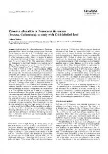
V, the PA strategy among users in TM is presented, and the joint resource allocation is researched. Section VI discusses simulation results. Finally, the conclusions and future work are presented in Section VII. II. S YSTEM D ESCRIPTION Consider an asymmetric interference network with K users as shown in Fig. 1. For the k-th pair, M [k] and N [k] antennas are equipped at its transmitter and receiver, respectively. Due to the asymmetric distribution of users, the large-scale fading gain from the i-th Tx to the j-th Rx ρ[ji] is introduced into the model as ( )−α ρ[ji] = r[ji] , (1) where r[ji] is the distance between the i-th Tx and the j-th Rx, and α represents the path-loss exponent determined by the wireless environment. Hence, the received signal with d[j] data streams at the j-th Rx can be expressed as y[j] =
K √ ∑ ρ[ji] U[j]† H[ji] V[i] x[i] + U[j]† z[j] ,
(2)
i=1
where H[ji] ∈ CN ×M denotes the small-scale fading gain from the i-th Tx to the j-th Rx, and each entity of H[ji] is i.i.d. with the complex Gaussian distribution CN (0, 1). The unitary [i] [i] [i] [i] matrices V[i] ∈ CM ×d and U[i] ∈ CN ×d represent the precoding and decoding matrices of the i-th pair, respectively. x[i] is the data streams from the i-th[ Tx to the ] i-th[k]Rx with a equal power constraint Pt , i.e., E ||x[i] ||2 = Pt = Pt . The additive Gaussian noise with distribution CN (0, σ 2 IN [j] ) [j] at the j-th Rx is denoted as z[j] ∈ CN ×1 . To take the advantage of asymmetric topology, a TM scheme was proposed in [14] to improve the spectrum efficiency of asymmetric IA-based interference networks, which will be briefly introduced in the next section. Notation: Id represents the d × d identity matrix. A† and |A| are the Hermitian transpose and determinant of matrix A, respectively. CM ×N is the space of complex M × N matrices. CN (a, A) is the complex Gaussian distribution with mean a and covariance matrix A. E{·} stands for expectation. Tr(A) is the trace of the matrix A. Table I lists some of the acronyms used in the paper. [j]
[i]
III. T OPOLOGY M ANAGEMENT OF I NTERFERENCE N ETWORKS In the proposed TM scheme of Fig. 1, according to the distribution of locations, the pairs close to each other will jointly comprise one IA subnetwork A, in which linear IA is adopted to eliminate the strong interference among IA pairs, and the weak inter-subnetwork interference is treated as noise. On the other hand, those pairs (the 2-nd and 5-th pairs in Fig. 1), which are far away from the others, will act as some SM subnetworks independently (belonging to the set S), in which SM is applied and the weak inter-subnetwork interference is also treated as noise. For simplicity and convenience, we assume that the antenna configuration of each pair is the same in the rest of this paper, i.e., M [j] = M , N [j] = N . Besides,
3
TABLE I L IST OF ACRONYMS
Acronym IA TM SM AS PA MIMO QoS CSI GP SNR SINR
IA subnetwork can be expressed as1 } { { } ρ[jj] Pt [jj] [jj]† [j] EH RIA = EH log2 Id + H H , [j] d(σ 2 + IIA ) (5) [jj] [j]† [jj] [j] d×d where H =U H V ∈C is the effective channel matrix. Proposition 1: In the TM scheme, the inter-subnetwork interference from other subnetworks is treated as noise, and [j] the power of the equivalent noise IIA can be expressed as ∑ [k] ∑ [j] Pt ρ[jk] = Pt ρ[jk] . (6) IIA =
Full form Interference Alignment Topology Management Spatial Multiplexing Antenna Selection Power Allocation Multi-input and Multi-output Quality of Service Channel State Information Geometric Programming Signal-to-Noise Ratio Signal-to-Interference-plus-Noise Ratio
k∈S
k∈S
Proof: In the IA subnetwork, when designing the precoding and decoding matrices for each IA pair based on the MinIL algorithm, the interferences from SM subnetworks are not considered in the process. Hence, for the j-th IA pair, the interferences from SM subnetworks cannot be eliminated. The received interferences can be expressed as ∑√ ˆ [k] x[k] . z[j] = ρ[jk] U[j]† H[jk] V (7) k∈S
ˆ [k] is designed in other subnetworks, In (7), the matrix V [j] and the matrix U only depends on the channel matrix H[jj] , ˆ[j] is also hence both of them are independent of H[jk] . Thus, z a complex Gaussian vector with its covariance matrix Q[j] as { } Q[j] = Ex z[j] z[j]† =
∑ P [k] t ˆ [k] V ˆ [k]† H[jk]† U[j] . ρ[jk] U[j]† H[jk] V d
(8)
k∈S
Fig. 1. A K-pair asymmetric IA-based interference network using topology management.
according to the TM scheme, when the j-th pair acts as an IA pair, the number of its data streams d[j] is set to d, whereas ˆ when it acts as an SM pair, d[j] is set to d. A. IA Strategy in the TM scheme In the IA subnetwork, to eliminate the interferences among IA pairs perfectly, the following conditions should be satisfied [7], [32]. U[j]† H[ji] V[i] = 0, ∀i ̸= j, i, j ∈ A, ) ( rank U[i]† H[ii] V[i] = d.
(3) (4)
Due to the difficulty of finding the closed-form solutions of IA problem especially when the number of users K is large, the distributed iterative algorithm, e.g., minimizing interference leakage (MinIL) algorithm [7], is leveraged to calculate the precoding matrices V ∈ CM ×d and decoding matrices U ∈ CN ×d for IA pairs. When each data stream is allocated with equal transmit power, the expected transmission rate of the j-th pair in the
ˆ [k] and U[j] are independent of the channel matrix As V H[jk] , according to the bi-unitarily invariant property [36], the ˆ [k] joint distribution of the entries of the matrix U[j]† H[jk] V is equal to that of H[jk] , i.e., the Wishart matrix W[jk] = ˆ Id ), and thus (8) in ˆ [k] V ˆ [k]† H[jk]† U[j] ∼ W(d, U[j]† H[jk] V averaged sense can be expressed as follow. { } { } ∑ P [k] [ ] t [j] [jk] [jk] EH Q = ρ E W . (9) dˆ k∈S
According to the property of the Wishart matrix [37], the mean ˆ and we have of Wishart matrix W[jk] is dI, ) ( { } ∑ P [k] t [jk] ˆ [j] ρ dId EH Q = dˆ k∈S ( ) (10) ∑ [jk] = Pt ρ Id . k∈S
Hence, the power of the equivalent noise can be expressed as (6). B. SM Strategy in the TM scheme For the j-th pair adopting the SM scheme, through the singular value decompositions of the channel matrix H[jj] , the 1 The BER performance in the system with base-band transmission can be also easily analyzed referred to the existing works [33]–[35].
4
precoding and decoding matrices of the pair can be obtained as follows [38]. ˆ [j] Σ[j] V ˆ [j]† , H[jj] = U
(11)
where the matrix Σ[j] is a diagonal matrix, whose diagonal elements are the singular values of the channel matrix H[jj] . ˆ [j] and U ˆ [j] , The right and left singular vector matrices, i.e., V are denoted as the precoding and decoding matrices of the j-th pair, respectively. In the SM subnetwork, when each data stream is allocated with equal transmit power, the expected transmission rate of the j-th pair can be represented as } { { } ρ[jj] Pt [j] [j] W EH RSM = EH log2 Idˆ + , (12) ˆ 2 + I [j] ) d(σ SM where dˆ = min (M, N ) represents the maximum rank of the channel matrix H, and the central Wishart matrix W[j] can described as { H[jj] H[jj]† N < M, W[j] = (13) [jj]† [jj] H H N ≥ M. [j]
The expression of the power of the equivalent noise ISM is similar to (6), and can be written as [j]
ISM =
K ∑ k=1,k̸=j
[k]
Pt ρ[jk] =
K ∑
Pt ρ[jk] .
(14)
k=1,k̸=j
In a feasible IA-based network with M + N = d(K + 1), after implementing TM, the whole network can be divided into several subnetworks, i.e., one IA subnetwork A and several SM subnetworks S. Therefore, the antennas of each pair in the IA subnetwork will be redundant because the number of IA pairs KIA is smaller than the number of all the users in the network K. To further improve the performance of the network, the resource allocation in the TM scheme is considered, and the two techniques, i.e., AS and PA, are adopted in this paper, which are summarized as follows. • Antenna Selection: When the antennas are redundant in the IA subnetwork, the performance of the IA subnetwork can be improved by selecting the optimal antenna combination for each IA pair. • Power Allocation: The transmitted power can be allocated among the pairs to further optimize the performance of the TM scheme. In the following sections, the combination of resource allocation and TM will be demonstrated in detail. IV. A NTENNA S ELECTION IN IA S UBNETWORK In this section, we first present the effectiveness of the AS technique to improve the spectrum efficiency of the IA subnetwork in the TM scheme. Then, a search method for the AS technique is developed. A. Effectiveness of AS Technique The AS technique is a valid approach to improve the performance of MIMO systems due to the supply of selection
diversity. To show the effectiveness of the AS technique in improving the spectrum efficiency of the IA subnetwork, Lemma 1 is represented as below. Lemma 1: When KIA < K, there will be more optional antenna combinations for IA pairs in the IA subnetwork. The expected performance of the IA cases based on these combinations is all the same with the following conditions being satisfied [j]
[j]
MIA + NIA ≥ d · (KIA + 1), [j]
[j]
d ≤ min {MIA , NIA }, [j]
(15)
[j]
where MIA and NIA are the number of antennas participating in the IA subnetwork at the Tx and Rx of the j-th pair, respectively. Proof: In the IA subnetwork, when designing the precoding matrix V[j] and decoding matrix U[j] for the j-th pair based on the MinIL algorithm [7], V[j] and U[j] are both independent of H[jj] . Therefore, the joint distribution of each [jj] entity of the effective channel H = U[j]† H[jj] V[j] is equal [jj] to that of H according to the properties of Wishart matrix [36]. Therefore, the changes of MIA and NIA will not affect the expectation of received signals power at the j-th pair, which can be expressed as { } [j] ( [jj] [jj]† ) Pt [k] EH = dPt = dPt . (16) Tr H H d From the above analysis, we can conclude that the expected transmission rate of the IA subnetwork will not be affected by the changes of MIA and NIA as long as (15) can be met. Remark 1: From Lemma 1, we can observe that the expected performance of the IA cases with different antenna combinations is the same as long as it is feasible. However, in each time slot, the instantaneous performance of each antenna combination may be quite different. Therefore, the performance of the IA subnetwork can be further improved through selecting the optimal antenna combination to perform IA in each time slot. B. Antenna Selection in IA Subnetwork of Topology Management To make the problem more clear to understand, we first take the interference network with (M, N, d, K) = (3, 3, 1, 5) as an example to analyze the implementation of the AS technique in the IA subnetwork. Assume that after performing TM, there exist one IA subnetwork with KIA = 4 pairs and KSM = 1 SM subnetwork in the network. Considering the CSI feedback overhead, the AS technique is just performed at the Rx side of each IA pair. According to (15), when the AS technique is applied to the IA subnetwork, the number of optional antenna combinations for the j-the IA pair can be summarized as Table II. Hence, there will be z = (3 + 1)4 = 256 available antenna combinations in the IA subnetwork, and the set of all z possible antenna combinations is denoted as Φ = {Ω1 , Ω2 , · · · , Ωz }.
5
N UMBER
OF
TABLE II O PTIONAL A NTENNA C OMBINATIONS FOR THE j- TH IA PAIR
Configuration [j] MIA [j] MIA
= =
[j] 3, NIA [j] 3, NIA
Antenna Combinations
= 2, d = 1
3
= 3, d = 1
1
pairs can be applied to optimize the performance of the network in each time slot. In Section II, we assume that each pair follows a equal power constraint Pt . Nevertheless, to perform PA strategy in more practical scenarios, the equal power allocation can be replaced by the sum power constraint as K ∑
Algorithm 1 Suboptimal search method to select the antenna combination Ω∗ 1: 2: 3: 4: 5: 6: 7:
8: 9: 10: 11:
ˆ = ∅. Set the search times Ith , the picked set Φ while i < Ith do Randomly without repetition pick an optional antenna ˆ =Φ ˆ ∪{Ωi }. combination Ωi from the set Φ, and Φ i = i + 1. end while ˆ do for each antenna combination Ωi ∈ Φ Perform the IA scheme in the IA subnetwork, and calculate the precoding matrices V and decoding matrices U. ∑KIA [k] Obtain R(Ωi ) = k=1 RIA (Ωi ). end for Search for the maximum value of R(Ωmax ) in the set {R(Ωi )|i = 1, 2, · · · , Ith }. Output the selected antenna combination Ω∗ = Ωmax .
To summarize the above analysis, we can select the optimal antenna combination from the set Φ to optimize the performance of IA subnetwork in each time slot through the AS technique, and the optimization problem can be expressed as {K } IA ∑ [k] ∗ Ω = arg max RIA (Ω) . (17) Ω∈Φ
k=1 [k] Pt
≤ KPt ,
(18)
≥ 0, ∀k ∈ {1, 2, · · · , K}.
Therefore, according to the PA strategy, equation (5) and (12) should be slightly modified as [jj] ρ [jj] [j] [jj]† [j] ˆ = log2 Id + R H H (19) P , t IA [j] (σ 2 + IIA ) [jj] ρ [j] [j] ˆ ˆ , R W (20) SM = log2 Idˆ + [j] (σ 2 + ISM ) where
{ ˆ [j] = W
[j]
H[jj] Pt H[jj]†
N < M,
[j] Pt H[jj]
N ≥ M.
H
[jj]†
(21)
[j]
The diagonal matrix Pt is the PA matrix of the j-th pair, whose diagonal elements are the transmit power allocated to each data stream, and the nondiagonal elements are zero. Based on the description above, the PA problem among pairs in asymmetric interference networks can be defined as ∑ [j] ∑ [j] ˆ + ˆ max R R IA SM [1]
[2]
[K]
Pt ,Pt ,...,Pt
j∈A
s.t.
k=1
The optimization problem (17) is a combinatorial optimization problem, and the exhaustive search method can be easily applied to solve it. Nevertheless, as the size of Φ becomes larger, the computational complexity of the exhaustive search method will become extremely high. To balance the computational complexity and the performance, a suboptimal method with limited search times Ith ≤ z is developed, which is summarized in Algorithm 1.
[k]
Pt
K ∑ k=1 [k]
Pt
[k]
Pt
j∈S
≤ KPt ,
(22)
≥ 0, ∀k ∈ {1, 2, · · · , K}.
To elaborate the problem (22) explicitly, we can redescribe the expressions of the rate of IA pairs and SM pairs in a more consolidated form. According to the matrix theory, we have the following identical equation d ( ) ∑ log2 Id + βAPA† = log2 1 + βp(l)λ[l] ,
(23)
l=1
V. P OWER A LLOCATION IN T OPOLOGY M ANAGEMENT In this section, we first describe the PA problem in TM. Then the GP framework is introduced to solve the PA problem, and finally, the joint resource allocation combining the AS and PA techniques for TM is developed.
where λ[l] is the l-th eigenvalue of the matrix AA† and p(l) is the l-th diagonal element of the diagonal matrix P. Based on equation (23), the problem (22) can be rewritten as K ∑ d[k] ) ( ∑ max log2 1 + SINR[k,l] , p(1,1),...,p(K,d[K] )
A. PA Problem in Topology Management Due to the asymmetric distribution of pairs, the path-loss in different wireless links may be various, which means that the level of the received signal-to-interference-plus-noise ratio (SINR) of pairs may be quite different. Therefore, taking the advantage of asymmetric topology, the PA strategy among
k=1 l=1 K ∑ d ∑
(24)
[k]
s.t.
p(k, l) ≤ KPt ,
k=1 l=1
p(k, l) ≥ 0, ∀k, l, ˆ and p(k, l) is the transmit power allocated where d[k] ∈ {d, d},
6
to the l-th data stream of the k-th pair, which satisfies d ∑
c1 > 0, the function f is also called a monomial, which can be simplified as
[k]
[k]
p(k, l) = Pt .
f (x) = cxa1 1 xa2 2 xa3 3 · · · xann .
(25)
(31)
l=1
SINR[k,l] represents the SINR for the l-th data stream of the k-th pair, which can be expressed as [kk] ρ p(k, l)λ[k,l] k ∈ A, [k] σ 2 + IIA [k,l] SINR = (26) ρ[kk] p(k, l)λ[k,l] k ∈ S, [k] σ 2 + ISM λ[k,l] is the eigenvalue corresponding to the l-th data stream of the k-th pair. Therefore, according to (24), the PA problem among pairs can be transformed into an equivalent PA problem among data streams. Proposition 2: Although the PA strategy is performed in [j] [j] TM, the expression of the equivalent noise IIA and ISM will not be affected. Proof: When the PA strategy is performed in the TM scheme of asymmetric interference networks, the received interference signal at the j-th IA pair can be expressed as ∑√ 1/2 ˆ [k] P[k] x ˆ[j] = ˆ [k] , z ρ[jk] U[j]† H[jk] V (27) t k∈S
[ [j] 2 ] [k] where E ||ˆ x || = 1, and Pt is the PA diagonal matrix of the k-th Tx. The corresponding covariance matrix can be given by ∑√ ˆ [k] P[k] V ˆ [k]† H[jk]† U[j] . (28) ˆ [j] = ρ[jk] U[j]† H[jk] V Q t k∈S
Hence, the expected power of the received interference signal can be given by (29) (on the next page). [j] Hence, the expression of IIA for IA pairs would not change, even though the PA strategy is performed in SM subnetworks. [j] The proof of the expression of ISM for SM pairs is analogous [j] to IIA . Due to the non-convexity of the problem (24), it is difficult to directly obtain the optimal PA strategy through convex optimization techniques. As an alternative approach, we apply the geometric programming (GP) framework, which is an effective method to solve the nolinear and nonconvex optimization problems, to perform the PA strategy in this paper.
A GP optimization problem in the standard form can be expressed as min f0 (x), s.t. fi (x) ≤ 1, i = 1, 2, · · · , m, ∑Ki
hi (x) = 1, i = 1, 2, · · · , p,
where fi (x) = k=1 cik xa1 i1k xa2 i2k · · · xanink , i = 0, 1, · · · , m are posynomials, and hi (x) = ci xa1 i1 x2ai2 x3ai2 · · · xanin , i = 1, 2, · · · , p are monomials. Generally, the GP problem in the standard form is not a convex optimization problem. However, the GP problem in the standard form can be converted into a convex optimization problem through a logarithmic change of the variables and the coefficients, i.e., yi = log xi , bik = log cik , bi = log ci . The GP problem in the convex form with the variables y can be written as min f˜0 (x)=log
K0 ∑
exp(aT0 y + b0k ),
k=1
s.t. f˜i (x)=log
Ki ∑
exp(aTi y + bik ) ≤ 0,i =1, 2,· · · ,m,
k=1
Consequently, the GP problem in the convex form can be effectively solved through convex optimization techniques, such as the interior-point method. Note that the difference between the GP problem (32) and (33) is just in the form of the object function and the constraint functions. The data of the two forms is equal due to the change of the form not involved in any operation. Because the object function does not satisfy the requirement of the GP framework, there need two transformations in the object function to make the problem tractable. First, we rewrite the problem (24) into an equivalent form as ) K ∏ d[k] ( ∏ 1 , min [k,l] p(1,1),...,p(K,d[K] ) 1 + SINR k=1 l=1 (34)
[k]
p(k, l) ≤ KPt ,
p(k, l) ≥ 0, ∀k, l.
To clearly present the method to solve the PA problem via GP, the brief introduction of the GP framework is presented as follows. Denote the function f : Rn+ → R as a posynomial, which can be expressed as: ck xa1 1k xa2 2k · · · xannk ,
K ∑ d ∑ k=1 l=1
B. Solving PA Problem in the TM scheme via GP
K ∑
(33)
˜ i (x)=aT y + bi = 0, i = 1, 2, · · · , p. h i
s.t.
f (x) =
(32)
(30)
k=1
where the coefficient ck ≥ 0, k = 1, 2, · · · , K, and ajk ∈ R, j = 1, 2 · · · , n, k = 1, 2, · · · , K. When K = 1 and c =
Through the first transformation, the maximization problem (24) is replaced with the equivalent minimization problem (34), which is required in the GP framework. Unfortunately, the object function in (34) is a ratio between two posynomials, which is still not a posynomial with optimization variables p(k, l), k = 1, 2, · · · , K, l = 1, 2, · · · , d[k] . Then, the object function in (34) will be approximated as a psoynomial through the condensation method [29] in the second transformation. In this paper, we take the following inequality, i.e., geometric mean approximation, to condense
7
{ ( )} EH Tr Q[j] = EH
{
(
Tr {
= EH =
∑
(
Tr
∑
)} [jk]
ρ
U
[j]†
[jk]
H
ˆ [k]
V
[k] ˆ [k]† [jk]† [j] Pt V H U
k∈S
∑
)} [k] ˆ [k]† [jk]† [j] [j]† [jk] ˆ [k] ρ[jk] Pt V H U U H V
(29)
k∈S [k]
Pt dρ[jk] .
k∈S
Algorithm 2 The GP-based PA strategy 1: 2: 3: 4: 5: 6: 7: 8: 9: 10:
Set the error tolerance ϵ, the initial error δ > ϵ, the iteration step n = 1. Choose an initial point p(n). while δ ≤ ϵ do Apply the condensation method to approximate the denominator polynomial as a posynomial using (35). Solve the GP in the convex form using an interior-point e. method, and generate p Calculate the error δ = ∥e p − p(n)∥. Update the iteration step, n = n + 1. e. Update the power variables, p(n) = p end while Output p(n).
the denominator polynomial of the object function in (34) as a posynomial2 . ∑ ∏ β βi vi ≥ vi i (35) i
i
where v ≻ 0 and β ≽ 0, 1T β = 1. Based on the above two transformations, the object function can be approximated as a posynomial. On the other hand, we can easily convert the constraint function into a posynomial through dividing KPt into both sides of the inequality. Finally, the optimization problem (24) is successfully converted to a GP problem. Considering only one approximation is not enough to accurately solve the original problem, hence a series of GP is required to perform iteratively, which is also called Complementary GP. The GP framework in the PA problem can be summarized in Algorithm 2. C. Joint Resource Allocation Resource allocation of the AS and PA techniques can be performed to further improve the performance of the TM scheme. Nevertheless, according to Sections IV-B and V-B, we can observe that the AS problem in IA subnetwork is a combinatorial optimization problem, while the PA strategy is a continuous optimization problem, which makes the joint optimization of the AS and PA techniques in the TM scheme much more difficult to solve. As a replacement of optimizing the joint optimization problem directly, a stepped resource 2 Note that there are many approaches to carry out the posynomial approximation. The more details about geometric mean approximation for the posynomial please refer to [29].
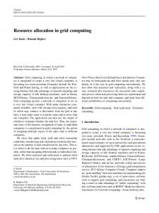
allocation optimization strategy is adopted for the TM scheme in each time slot, which can be described as follows. • Step 1: In an asymmetric network, we first utilize the TM scheme to obtain the network topology. • Step 2: Based on the network topology, the AS technique is applied to select the optimal antenna combination in the IA subnetwork. • Step 3: According to the network topology and the optimal antenna combination of the IA subnetwork, the PA strategy among data streams is performed in the whole network. There are also something to be stated to make the stepped resource allocation optimization problem more clearly, which is summarized in Remark 2. Remark 2: • When no SM subnetworks exist, Step 2 will be omitted. This is because there are no redundant antennas under the condition M + N = d · (K + 1). • Due to the PA strategy in certain time slots, the transmit power allocated to some pairs may be zero. These pairs will keep silent or turn into sleep mode in these slots accordingly. • The implementation of the AS and PA techniques will not affect the topology of the network in each time slot. VI. S IMULATION R ESULTS AND D ISCUSSIONS In this paper, we assume that perfect CSI can be obtained at each pair, and the path-loss exponent α is set to 3 according to [39]. For the small-scale fading, the slow Rayleigh fading model is considered. All the pairs are randomly and uniformly distributed in a 10 × 10 km square area, and the distance between the i-th Tx and its corresponding Rx is set to 1 km, ∀i ∈ {1, 2, · · · , K}. We first consider an asymmetric interference network with the configuration (M, N, d, K) = (3, 3, 1, 5). An example of the network with 5 pairs randomly distributed in the square area is shown in Fig. 2. In the following, we will take this certain asymmetric interference network to analyze the resource allocation in the TM scheme. In Fig. 3 and Fig. 4, we present certain topologies of the asymmetric interference network (shown in Fig. 2) through TM when the transmit signal-to-noise ratio (SNR) is 4 dB and 10 dB, respectively. From Fig. 3, we can find that when the transmit SNR is 4 dB, these pairs, i.e., the 2-nd, 3-rd and 4-th pairs, gather together as one IA subnetwork, and the 1-st and 5-th pairs act as an independent SM subnetwork, respectively. As the transmit SNR increases to 10 dB, the 1-st pair is fused
8
10
10 Tx Rx
Rx1 9
Rx1 9
Tx1
Tx1
8
8 Rx4
Rx4 7
Tx4
Location in Y (km)
Location in Y (km)
7 6 Rx2
5
Tx2
Rx3 Tx3
4
IA Subnetwork Tx4
6 Rx2
5
Tx2
Rx3 Tx3
4 SM Subnetwork
3
Tx5
3
Tx5
Rx5
2
Rx5
Tx Rx
2 1 1 0
Fig. 2.
0
2
4 6 Location in X (km)
8
10
An example of asymmetric interference networks with 5 pairs. 10
0
Rx1 SM Subnetwork
Spectrum Efficiency (bits/s/hz)
Location in Y (km)
Tx4 6 Rx3 Tx3
4 IA Subnetwork 3
SM Subnetwork Tx5 Rx5
Tx Rx
16 15.5 15
SNR = 10 dB with AS
14.5 SNR = 12 dB without AS 14 13.5 13
1 0
SNR = 10 dB without AS
12.5 0
2
10
16.5
Rx4 7
2
8
SNR = 12 dB with AS
17
8
Tx2
4 6 Location in X (km)
17.5
Tx1
Rx2
2
Fig. 4. A certain topology of the interference network with 5 pairs when the transmit SNR is 10 dB.
9
5
0
4 6 Location in X (km)
8
10
Fig. 3. A certain topology of the interference network with 5 pairs when the transmit SNR is 4 dB.
into the IA subnetwork, and the 5-th pair still acts as an SM pair shown in Fig. 4. Note that Fig. 3 and Fig. 4 are just specific examples for demonstrating the TM scheme, and the topology of the network may be varying according to different SNRs and the locations of users. Based on the obtained network topology, we compare the spectrum efficiency of the IA subnetwork with/without the AS technique under different transmit SNRs in Fig. 5. From the figure, we can observe that the performance of the IA subnetwork can be effectively improved through the IA technique. As the search times Ith increases, the performance of the IA subnetwork with the AS technique at both of 10 and 12 dB can be improved gradually. This is because that the larger Ith will provide more optional antenna combinations and increase the selection diversity. However, the larger Ith will also increase the computational complexity of the search method concurrently. Therefore, Ith should be chosen according to different requirements of the system. In other words, we can set Ith
12
0
10
20
30
40
50
60
70
Ith
Fig. 5. The comparison of the spectrum efficiency of the IA subnetwork with/without the AS technique when the transmit SNR is 10 and 12 dB.
larger to achieve better performance, or set it smaller to lower the computational complexity. To balance the performance and the computational complexity, the search times Ith is set to 16 in the following of this paper. Compared to the exhaustive search method of the AS technique, there exists some performance loss due to the application of the suboptimal search method. According to the performance analysis of AS in [20], guaranteed performance with relatively low computational complexity can be achieved through carefully setting the search times Ith . For the GP-based PA strategy, we randomly select one certain time slot to analyze its performance. In Fig. 6, we show the convergence of power variables in the GP framework when the transmit SNR is 10 dB. In the initial point, the power allocated to each data stream is equal. As shown in the figure, the power allocated to the 5-pair is the largest. This is because that the 5-th pair acts as an SM pair in the TM scheme, more data streams can be transmitted based
9
2.2
50 Pair 1 Pair 2 Pair 3 Pair 4 Pair 5
2
40 Spectrum Efficiency (bits/s/hz)
Allocated power
1.8
MinIL MinIL−based TM MinIL−based TM with AS MinIL−based TM with PA MinIL−based TM with AS and PA
45
1.6
1.4
1.2
1
35 30 25 20 15 10
0.8
5
1
2
3
4
5
6 7 8 Number of iterations
9
10
11
12
Fig. 6. Convergence of power variables in the GP framework when the transmit SNR is 10 dB.
23.2
Spectrum Efficiency (bits/s/hz)
23
22.8
22.6
22.4
22.2 Equal PA 22
21.8
1
2
3
4
5
6 7 8 Number of iterations
9
10
11
12
Fig. 7. Convergence of the spectrum efficiency of the whole network when the transmit SNR is 10 dB (corresponding to Fig. 6).
on the SM technique compared with the IA technique, and thus more power will be allocated to it according to the PA strategy among data streams. Accordingly, the convergence of the spectrum efficiency of the whole network is analyzed in Fig. 7. Compared to the equal PA strategy, the GP-based PA strategy can indeed achieve better performance. As shown in the results, the convergence of power variables and spectrum efficiency is fast, which can be almost achieved by 4-th GP iteration. Note that although the PA strategy is performed though a GP-based approximation, the found solution is very likely to converge to or very close to the global optimum [29]. Hence, the performance loss is trivial when the GP-based PA strategy is performed in the TM scheme. The spectrum efficiency of different schemes in the asymmetric IA-based interference network with 5 pairs is compared in Fig. 8. We consider five MinIL algorithm based schemes, including the MinIL scheme, the MinIL-based TM scheme, the MinIL-based TM scheme with AS, the MinIL-based TM scheme with PA, the MinIL-based TM scheme with AS
0 −10
−5
0
5
10 15 Transmit SNR (dB)
20
25
30
Fig. 8. The spectrum efficiency versus the transmit SNR in the asymmetric interference network with 5 pairs using different TM schemes.
and PA. From the results, we can observe that separately applying one resource allocation technique (e.g., AS or PA) in the MinIL-based TM scheme can effectively improve the performance of the network compared with the conventional TM scheme. Meanwhile, the MinIL-based TM scheme with AS and PA can achieve the optimal performance among the five schemes due to the joint optimization of AS and PA. The MinIL-based TM scheme with AS and PA can achieve around 20% gain of the spectrum efficiency compared to the original MinIL-based TM scheme in the transmit SNR region from -6 dB to 20 dB. The figure shows that there are some turn points on the spectrum efficiency curves in some transmit SNRs, such as 6 dB and 22 dB. This is because that the increase of the transmit SNR will change the adopted scheme of some pairs (e.g., IA or SM), which results in these turn points. The performance of asymmetric interference networks with more pairs is also considered in this paper. When the transmit SNR is 10 dB, a certain topology of the asymmetric interference network with (M, N, K, d) = (4, 4, 7, 1) is shown in Fig. 9. Correspondingly, the spectrum efficiency of the asymmetric interference network versus the transmit SNR is presented in Fig. 10. From the results, we can observe that when the number of pairs becomes larger in the network, the proposed schemes are also effective to improve the performance. VII. C ONCLUSIONS AND F UTURE W ORK In this paper, resource allocation, i.e., AS and PA, in the TM scheme were investigated to improve the spectrum efficiency of asymmetric interference networks. First, the TM scheme proposed in [14] was applied to perform the partition of the networks. After performing the TM scheme, the antenna resource will be relatively redundant for designing the IA solution in IA subnetwork. Hence, the AS technique can be applied to improve the spectrum efficiency of IA subnetwork through the selection diversity gain. In addition, the PA technique can be also applied in the TM scheme. Based on the GP framework, the transmit power was allocated among the transmitters of both the IA and SM subnetworks to improve
10
10
R EFERENCES Tx5
9
Rx5 8 SM Subnetwork
Rx7
Location in Y (km)
7
Tx7
6 5
Rx3
Tx3
4
Rx6 Rx2
3
Tx2 Tx6 Tx4 Rx4
2
Tx1 Rx1
Tx Rx
1 0
0
IA Subnetwork
2
4 6 Location in X (km)
8
10
Fig. 9. A certain topology of the interference network with 7 pairs when the transmit SNR is 10 dB. 60
Spectrum Efficiency (bits/s/hz)
50
40
MinIL MinIL−based TM MinIL−based TM with AS MinIL−based TM with PA MinIL−based TM with AS and PA
30
20
10
0 −10 −8 −6 −4 −2
0
2
4 6 8 10 12 14 16 18 20 22 24 Transmit SNR (dB)
Fig. 10. The spectrum efficiency versus the transmit SNR in the asymmetric interference network with 7 pairs using different TM schemes.
the spectrum efficiency. Finally, a stepped resource allocation strategy for the joint optimization of the AS and PA techniques was developed to further improve the performance with low computational complexity. From the simulation results, we can observe that around 20% gain can be achieved by the stepped resource allocation strategy in the asymmetric interference network with 5 pairs in the transmit SNR region from -6 dB to 20 dB, which has shown the effectiveness of the proposed resource allocation strategy. In our future work, large-scale networks with Poisson point process [40] will be considered in the proposed framework. VIII. ACKNOWLEDGEMENT We thank the editor and reviewers for their detailed reviews and constructive comments, which have helped to improve the quality of this paper.
[1] X. Zhang, N. Zhao, F. R. Yu, and V. C. M. Leung, “Resource allocation in topology management of asymmetric wireless interference networks,” in Proc. IEEE VTC’16-Spring, pp. 1–5, Nanjing, China, May 2016. [2] S. Zhang, S. C. Liew, and J. Chen, “The capacity of known interference channel,” IEEE J. Sel. Areas Commun., vol. 33, no. 6, pp. 1241–1252, Jun. 2015. [3] Y. Zhou, H. Liu, Z. Pan, L. Tian, J. Shi, and G. Yang, “Two-stage cooperative multicast transmission with optimized power consumption and guaranteed coverage,” IEEE J. Sel. Areas. Commun., vol. 32, no. 2, pp. 274–284, Feb. 2014. [4] V. R. Cadambe and S. A. Jafar, “Interference alignment and degrees of freedom of the K-user interference channel,” IEEE Trans. Inf. Theory, vol. 54, no. 8, pp. 3425–3441, Aug. 2008. [5] N. Zhao, F. R. Yu, and V. C. M. Leung, “Opportunistic communications in interference alignment networks with wireless power transfer,” IEEE Wireless Commun., vol. 22, no. 1, pp. 88–95, Feb. 2015. [6] N. Zhao, F. R. Yu, M. Jin, Q. Yan, and V. C. M. Leung, “Interference alignment and its applications: A survey, research issues and challenges,” IEEE Commun. Surveys Tuts., to appear. [7] K. Gomadam, V. R. Cadambe, and S. A. Jafar, “A distributed numerical approach to interference alignment and applications to wireless interference networks,” IEEE Trans. Inf. Theory, vol. 57, no. 6, pp. 3309–3322, Jun. 2011. [8] C. Suh, M. Ho, and D. N. C. Tse, “Downlink interference alignment,” IEEE Trans. Commun., vol. 59, no. 9, pp. 2616–2626, Sept. 2011. [9] B. Nazer, M. Gastpar, S. A. Jafar, and S. Vishwanath, “Ergodic interference alignment,” IEEE Trans. Inf. Theory, vol. 58, no. 10, pp. 2616– 2626, Oct. 2012. [10] O. E. Ayach, S. W. Peters, and R. W. Heath, Jr., “The practical challenges of interference alignment,” IEEE Wireless Commun., vol. 20, no. 1, pp. 35–42, Feb. 2013. [11] X. Rao, L. Ruan, and V. K. N. Lau, “Limited feedback design for interference alignment on MIMO interference networks with heterogeneous path loss and spatial correlations,” IEEE Trans. Signal Process., vol. 61, no. 10, pp. 2598–2607, May 2013. [12] H. Huang and V. K. N. Lau, “Partial interference alignment for K-user MIMO interference channels,” IEEE Trans. Signal Process., vol. 59, no. 10, pp. 4900–4908, Oct. 2011. [13] S. Chen and R. S. Cheng, “Clustering for interference alignment in multiuser interference network,” IEEE Trans. Veh. Technol., vol. 63, no. 6, pp. 2613–2624, Jul. 2014. [14] X. Zhang, F. R. Yu, Y. He, and N. Zhao, “Spectrum-efficient topology management of asymmetric interference alignment networks,” in Proc. IEEE ICCC’14, pp. 627–631, Shanghai, China, Oct, 2014. [15] R. W. Heath, A. Paulraj, and S. Sandhu, “Antenna selection for spatial multiplexing systems with linear receivers,” IEEE Commun. Lett., vol. 5, no. 4, pp. 142–144, Apr. 2001. [16] S. Sanayei and A. Nosratinia, “Antenna selection in MIMO systems,” IEEE Commun. Mag., vol. 42, no. 10, pp. 68–73, Oct. 2004. [17] A. F. Molisch and M. Z. Win, “MIMO systems with antenna selection,” IEEE Microw. Mag., vol. 5, pp. 46–56, Mar. 2004. [18] J. G. Koltz and A. Sezgin, “Antenna selection criteria for interference alignment,” in Proc. IEEE PIMRC’10, pp. 527–531, Instanbul, Sept. 2010. [19] N. Zhao, F. R. Yu, H. Sun, A. Nallanathan, and H. Yin, “A novel interference alignment scheme based on sequential antenna switching in wireless networks,” IEEE Trans. Wireless Commun., vol. 12, no. 10, pp. 5008–5021, Oct. 2013. [20] X. Li, N. Zhao, Y. Sun, and F. R. Yu, “Interference alignment based on antenna selection with imperfect channel state information in cognitive radio networks,” IEEE Trans. Veh. Technol., to Appear. [21] D. N. Tse, “Optimal power allocation over parallel gaussian broadcast channels,” in in Proc. ISIT 1997, p. 27, Ulm, Germany, 1997. [22] M. O. Hasna and M. Alouini, “Optimal power allocation for relayed transmissions over rayleigh-fading channels,” IEEE Trans. Wireless Commun., vol. 3, no. 6, pp. 1999–2004, Nov. 2004. [23] T. Yoo and A. Goldsmith, “Capacity and power allocation for fading MIMO channels with channel estimation error,” IEEE Trans. Inf. Theory, vol. 52, no. 5, pp. 2203–2214, May 2006. [24] H. H. Kha, H. D. Tuan, and H. H. Nguyen, “Fast global optimal power allocation in wireless networks by local D.C. programming,” IEEE Trans. Wireless Commun., vol. 11, no. 2, pp. 510–515, Dec. 2011. [25] J. Zheng, Y. Cai, Y. Liu, Y. Xu, B. Duan, and X. Shen, “Optimal power allocation and user scheduling in multicell networks: Base station cooperation using a game-theoretic approach,” IEEE Trans. Wireless Commun., vol. 13, no. 12, pp. 6928–6942, Dec. 2014.
11
[26] N. U. Hassan, C. Yuen, S. Saeed, and Z. Zhang, “Power control for sumrate maximization on interference channels under sum power constraint,” IEEE Trans. Veh. Technol., vol. 64, no. 2, pp. 593–605, Feb. 2015. [27] N. Zhao, F. R. Yu, and H. Sun, “Adaptive energy-efficient power allocation in green interference alignment wireless networks,” IEEE Trans. Veh. Technol., vol. 64, no. 9, pp. 4268–4281, Sept. 2015. [28] S. Kandukur and S. Boyd, “Optimal power control in interferencelimited fading wireless channels with outage-probability specifications,” IEEE Trans. Wireless Commun., vol. 1, no. 1, pp. 46–55, Jan. 2002. [29] M. Chiang, C. W. Tan, D. Palomar, D. ONeill, and D. Julian, “Power control by geometric programming,” IEEE Trans. Wireless Commun., vol. 6, no. 7, pp. 2640–2651, Jul. 2007. [30] K. Phan, T. Le-Ngoc, S. Vorobyov, and C. Tellambura, “Power allocation in wireless relay networks: a geometric programming-based approach,” in Proc. IEEE Globecom’08, pp. 1–5, New Orleans, LO, 2008. [31] S. Boyd and L. Vandenberghe, Convex Optimization. Cambridge, U.K.: Cambridge Univ. Press, 2009. [32] C. Yetis, T. Gou, S. A. Jafar, and A. Kayran, “On feasibility of interference alignment in MIMO interference networks,” IEEE Trans. Signal Process., vol. 58, no. 9, pp. 4771–4782, Sept. 2010. [33] K. M. F. Elsayed and M. H. Ismail, “Exploiting interference alignment for sum rate enhancement in D2D-enabled cellular networks,” in Proc. IEEE WCNC’12, pp. 1624–1629, Shanghai, China, Apr. 2012. [34] B. Guler and A. Yener, “Selective interference alignment for MIMO cognitive femtocell networks,” IEEE J. Sel. Areas Commun., vol. 32, no. 3, pp. 439–450, Mar. 2014. [35] L. Bai and L. Hao, “New interference alignment algorithms based on desired signals for two-cell MIMO interfering multiple-access channels,” IEEE Commun. Lett., vol. 19, no. 6, pp. 997–1000, Jun. 2015. [36] A. M. Tulino and S. Verdu, “Random Matrix Theory and Wireless Communications,” Found. Trends Commun. Inf. Theory, vol. 1, no. 1, pp. 1–182, 2004. [37] M. S. Srivastava and C. G. Khatri, An Introduction to Multivariate Statistics. North-Holland, Amsterdam, 1979. [38] D. Tse and P. Viswanath, Fundamentals of Wireless Communication. Cambridge, U.K.: Cambridge Univ. Press, 2005. [39] T. S. Rappaport, Wireless Communications Principles and Practices. Prentice-Hall, 2002. [40] H. ElSawy, E. Hossain, and M. Haenggi, “Stochastic geometry for modeling, analysis, and design of multi-tier and cognitive cellular wireless networks: A survey,” IEEE Commun. Surv. Tutor., vol. 15, no. 3, pp. 996–1019, 2013.
Xinyu Zhang (S’14) is currently a graduate student in the School of Information and Communication Engineering at Dalian University of Technology, Dalian, China. He received the B.S. degree in Electronic and Information Engineering from Dalian University of Technology. His current research interests include interference alignment, resource allocation, and network optimization.
Nan Zhao (S’08-M’11-SM’16) is currently an Associate Professor in the School of Information and Communication Engineering at Dalian University of Technology, China. He received the B.S. degree in electronics and information engineering in 2005, the M.E. degree in signal and information processing in 2007, and the Ph.D. degree in information and communication engineering in 2011, from Harbin Institute of Technology, Harbin, China. From Jun. 2011 to Jun. 2013, Nan Zhao did postdoctoral research in Dalian University of Technology, Dalian, China. His recent research interests include Interference Alignment, Cognitive Radio, Wireless Power Transfer, and Optical Communications. He has published more than 70 papers in refereed journals and international conferences. Dr. Zhao is a member of the IEEE and a senior member of the Chinese Institute of Electronics. He serves as an Editor of Wireless Networks, AEU-International Journal of Electronics and Communications, Ad Hoc & Sensor Wireless Networks, and KSII Transactions on Internet and Information Systems. Additionally, he served as a technical program committee (TPC) member for many interferences, e.g., Globecom, VTC, WCSP.
F. Richard Yu (S’00-M’04-SM’08) received the PhD degree in electrical engineering from the University of British Columbia (UBC) in 2003. From 2002 to 2006, he was with Ericsson (in Lund, Sweden) and a start-up in California, USA. He joined Carleton University in 2007, where he is currently an Associate Professor. He received the IEEE Outstanding Leadership Award in 2013, Carleton Research Achievement Award in 2012, the Ontario Early Researcher Award (formerly Premiers Research Excellence Award) in 2011, the Excellent Contribution Award at IEEE/IFIP TrustCom 2010, the Leadership Opportunity Fund Award from Canada Foundation of Innovation in 2009 and the Best Paper Awards at IEEE ICC 2014, Globecom 2012, IEEE/IFIP TrustCom 2009 and Int’l Conference on Networking 2005. His research interests include cross-layer/cross-system design, security, green IT and QoS provisioning in wireless-based systems. He serves on the editorial boards of several journals, including Co-Editorin-Chief for Ad Hoc & Sensor Wireless Networks, Lead Series Editor for IEEE Transactions on Vehicular Technology, IEEE Communications Surveys & Tutorials, EURASIP Journal on Wireless Communications Networking, Wiley Journal on Security and Communication Networks, and International Journal of Wireless Communications and Networking. He has served as the Technical Program Committee (TPC) Co-Chair of numerous conferences. Dr. Yu is a registered Professional Engineer in the province of Ontario, Canada.
Minglu Jin is a professor in the School of Information and Communication Engineering at Dalian University of Technology, Dalian, China. He received the Ph.D. and M.Sc. degrees from Beihang University, Beijing, China, the B.Eng. degree from University of Science & Technology, Hefei, China. He was a Visiting scholar in the Arimoto Lab. at Osaka University, Osaka, Japan, from 1987 to 1988. He was a Research Fellow in Radio & Broadcasting Research Lab at Electronics Telecommunications Research Institute (ETRI), Korea, from 2001 to 2004. Professor Jin’s research interests are in the general areas of signal processing and communications systems. Specific current interests are Cognitive radio, Multiple-Input and Multiple-Output (MIMO) radio antenna design and wireless sensor networks.
12
Victor C. M. Leung (S’75-M’89-SM’97-F’03) received the B.A.Sc. (Hons.) degree in electrical engineering from the University of British Columbia (UBC) in 1977, and was awarded the APEBC Gold Medal as the head of the graduating class in the Faculty of Applied Science. He attended graduate school at UBC on a Natural Sciences and Engineering Research Council Postgraduate Scholarship and completed the Ph.D. degree in electrical engineering in 1981. From 1981 to 1987, Dr. Leung was a Senior Member of Technical Staff and satellite system specialist at MPR Teltech Ltd., Canada. In 1988, he was a Lecturer in the Department of Electronics at the Chinese University of Hong Kong. He returned to UBC as a faculty member in 1989, and currently holds the positions of Professor and TELUS Mobility Research Chair in Advanced Telecommunications Engineering in the Department of Electrical and Computer Engineering. Dr. Leung has co-authored more than 900 technical papers in international journals and conference proceedings, 31 book chapters, and co-edited 11 book titles.
Several of his papers had been selected for best paper awards. His research interests are in the areas wireless networks and mobile systems. Dr. Leung is a registered Professional Engineer in the Province of British Columbia, Canada. He is a Fellow of IEEE, the Royal Society of Canada, the Engineering Institute of Canada, and the Canadian Academy of Engineering. He was a Distinguished Lecturer of the IEEE Communications Society. He is a member of the editorial boards of the IEEE Wireless Communications Letters, IEEE Journal on Selected Areas in Communications Series on Green Communications and Networking, IEEE Access, Computer Communications, and several other journals, and has previously served on the editorial boards of the IEEE Journal on Selected Areas in Communications C Wireless Communications Series, IEEE Transactions on Wireless Communications, IEEE Transactions on Vehicular Technology, IEEE Transactions on Computers, and Journal of Communications and Networks. He has guest-edited many journal special issues, and provided leadership to the organizing committees and technical program committees of numerous conferences and workshops. He was a recipient of the IEEE Vancouver Section Centennial Award and 2012 UBC Killam Research Prize.