Çankaya University Journal of Science and Engineering Volume 13, No. 1 (2016) 040-057
Resource Efficient Implementation of the Keccak, Skein & JH Algorithms on a Reconfigurable Platform Dur-e-Shahwar Kundi, Arshad Aziz, Kashif Latif Department of Electrical Engineering (PNEC), National University of Sciences and Technology (NUST), H-12 Islamabad, Pakistan e-mail:
[email protected],
[email protected],
[email protected]
Abstract: In this work, we present a compact hardware implementation of cryptographic hash algorithms; [Keccak, Skein & JH] on Field Programmable Gate Array (FPGA) by using an efficient primitive level programming approach. All the logic is not only mapped onto Look-Up-Table (LUT) but also effectively utilizes FPGAs internal dedicated logical resource, such as Fast Carry Chain logic with MUXCY and XORCY to reduce overall hardware resources. This approach results in the usage of a minimized chip area with a good balance between resources and speed for selected hash algorithms. All the implementation has been done on the latest Xilinx FPGAs and their results comparisons are presented in the form of chip area consumption, throughput and throughput per area with previous up-to-date implementations. The results show a substantial improvement as compared to all the previously reported works. Keywords: Cryptographic Hash Functions, FPGA, JH, Keccak, Skein, SHA-3.
1. Introduction Cryptographic hash functions are an essential component in many information security applications such as digital signatures, message authentication codes (MACs) that require authentication, and data integrity. A secure cryptographic hash function must have two important properties: it should be irreversible and it should be collision free. However, many previous hash functions and cryptographic hash functions, such as SHA-0, SHA-1, RIPEMD, MD4, MD5, and HAVAL, have been found vulnerable to pre-image and collision attacks and should not be used because of their weaknesses [1-4].
ISSN 1309 – 6788 © 2016 Çankaya University
CUJSE 13, No. 1 (2016)
41
Therefore, to ensure the long-term robustness of applications that use hash functions, the National Institute of Standards and Technology (NIST) USA has selected Keccak as a new cryptographic hash algorithm called SHA-3 [5] in 2012. Though Keccak is selected as a standard hash algorithm, the four remaining proposed hash algorithms candidates (Skein, BLAKE, JH and Grøstl) were also equally as good and provide flawless security [6]. Similarly, the design of JH and Grøstl are strongly inspired by AES [7] and both can be a good choice once we require unified architecture with encryption algorithm, such as AES. Therefore, in this paper, we provide an efficient hardware implementation of only three selected SHA-3 candidates: Keccak as SHA-3, Skein and JH with respect to unified architecture on the latest Field Programmable Gate Array (FPGA) technologies from Xilinx. FPGAs are the best known leading reconfigurable platform for hardware implementation. All modern Xilinx FPGAs [8] are equipped with Configurable Logic Blocks (CLBs) that contain not only Look-Up-Tables (LUTs) but also dedicated hardware resources, such as Fast Carry Chain logic, MUXCY and XORCY gates. These resources can be effectively utilized to speed up the operation of cryptographic hash algorithms with minimum area resources. The remainder of this paper is organized as follows: An overview of related work is discussed in Section 2. In Section 3, the methodology adopted for our hardware implementation of Keccak, Skein & JH is described. The resource efficient hardware architectures for Keccak, Skein & JH with their brief overview are given in Section 4. In Section 5, we present the implementation results and comparisons with previously reported work. Section 6 provides performance evaluation of Keccak, Skein & JH. Finally, we conclude our work in Section 7.
2. Related Work Various groups around the world provide the hardware implementation for the above selected algorithms on both the FPGA and ASIC platforms in two main categories of implementation: high speed designs and compact designs. The high speed ASIC implementations are reported in [9-11]. A number of efficient compact FPGA implementations of these algorithms are reported in [12-15]. In this work, we focus on high-speed implementations of FPGAs as it provides a direct snapshot of the basic operations cost for a given algorithm. The SHA-3 Zoo website [16] reports the comprehensive results of the reported work, in which most are focused on high speed architectures. In Table 1, we provide a snapshot of the high-speed implementations results for FPGAs from different groups. The comprehensive studies on the above selected algorithms are reported by Baldwin et al. [17], Matsuo et al. [18], Gaj et al.
42
Kundi et al.
[19], Shahid et al. [20] and Homsirikamol et al. [21, 22]. In [17-22], the authors have investigated different design strategies and have implemented various architectures for every algorithm using pipelining, folding and loop unrolling approaches. However, here we have selected only the results of the basic iterative architecture (x1) for Keccak, basic iterative architecture with 4 unrolled stages (x4) for Skein and basic iterative architecture (x1) with memory for JH.
TABLE 1. SHA-3 Candidates Implementations SHA-3 candidates
256-bit Author(s)
Device
512-bit
𝑭𝒎𝒎𝒎
122.00
𝑨𝑨𝑨𝑨 1330
𝑻𝑻
5.20
𝑻𝑻𝑻 3.91
𝑭𝒎𝒎𝒎 -
𝑨𝑨𝑨𝑨 -
𝑻𝑻 -
𝑻𝑻𝑻 -
-
Keccak Team [27]
Virtex-5
Strömbergson [23]
Spartan-3
85.00
3393
4.80
1.41
-
-
-
Strömbergson [23]
Virtex-5
118.00
1483
6.70
4.52
-
-
-
Baldwin et al.[17]
Virtex-5
195.73
1971
6.26
3.17
195.73
1971
8.52
4.32
Matsuo et al. [18]
Virtex-5
205.00
1433
4.20
2.93
-
-
-
-
-
-
-
-
-
-
-
Keccak Akin et al. [24]
Spartan-3
81.40
2024
3.46
1.71
Akin et al. [24]
Virtex-4
142.90
2024
6.07
3.00
Gaj et al. [19]
Virtex-5
-
1375
12.75
9.27
-
1283
7.18
5.60
Homsirikamol et al. [22] Virtex-6
-
1165
11.84 10.17
-
1231
7.23
5.87
-
1395
12.77
9.16
-
1220
6.56
5.37
248.2
1338
11.25
8.41
-
-
-
-
Homsirikamol et al. [22] Virtex-5
Skein
JH
Shahid et al.[20]
Virtex-5
Baldwin et al. [17]
Virtex-5
-
-
-
-
83.58
2756
0.97
0.35
Matsuo et al. [18]
Virtex-5
115.00
854
0.283
0.33
-
-
-
-
Gaj et al. [19]
Virtex-5
-
1245
3.13
2.51
-
1348
2.97
2.20
Long [25]
Virtex-5
114.94
931
0.407
0.44
114.94
1758
0.82
0.46
Tillich [26]
Virtex-5
68.40
937
1.751
1.87
69.04
1632 3.535 2.17
Tillich [26]
Spartan-3
26.14
2421
0.669
0.28
26.66
4273 1.365 0.32
Homsirikamol et al. [22] Virtex-6
-
1216
3.52
2.90
-
1591
3.11
1.96
Homsirikamol et al. [22] Virtex-5
-
1476
2.94
1.99
-
1658
2.81
1.7
Shahid et al.[20]
Virtex-5
95.2
1306
2.56
1.96
-
-
-
-
Baldwin et al.[17]
Virtex-5
144.11
1763
1.64
0.93
144.11
1763
1.64
0.93
Matsuo et al. [18]
Virtex-5
201.00
2661
0.733
0.27
-
-
-
Gaj et al. [19]
Virtex-5
-
1001
4.54
4.54
-
Homsirikamol et al. [22] Virtex-6
-
847
5.70
6.73
-
896
5.34
5.95
Homsirikamol et al. [22] Virtex-5
-
909
4.62
5.09
-
1020
4.73
4.64
354.7
985
5.04
5.12
-
-
-
-
Shahid et al.[20]
Virtex-5
𝐹𝑚𝑚𝑚 in MHz, 𝐴𝐴𝐴𝐴 in Slices, 𝑇𝑇 in Gbps and 𝑇𝑇𝑇 in Mbps/Slice
1125 4533
4.03
CUJSE 13, No. 1 (2016)
43
3. Implementation Methodology We have implemented the 256-bit and 512-bit variants of the selected SHA-3 candidates: Keccak, Skein & JH. Our designs are fully autonomous with complete I/O interfaces. We targeted them for efficient implementations; however, we kept in mind the fair hardware performance comparison for these candidates.
3.1. I/O Interface The input/output interface is shown in Fig. 1(a). Each I/O transaction is sampled at the rising edge of the system clock. The input cycle is started by setting the load signal to high. After that, the Hash Module sets the ack signal to high if it is able to receive input data. The input data is then received in the form of 64-bit words at every rising edge of the clock, and during this transaction, the ack signal remains high. When the Hash Module has received the desired amount of data_in, then this ack signal is set to low by it, and if no further transactions are required, then the load signal is pull down to low by the I/O Interface. Similarly, when the final hash value becomes available by the Hash Module, then hash_valid is set to high by it. The output data is then transferred in the form of 64-bit words on each rising edge of the clock until the desired hash length is received.
3.2. Control and Data Paths The hash module has two major parts: the control path and the data path. The block diagram of the hash module is given in Fig. 1(b). The control path consists of the Finite State Machine, State register, clock and counter, while the data path consists of input and output registers, the Hash Core and intermediate registers. The input registers of the data path consists of registers input
clock
clock
hash_valid data_in 64
data_out
Clock
Hash Module
Control Path
I/O Interface
load ack
Counter
Input Registers
reset select
Hash Core FSM Logic
hash_en
State Reg
hash_done
Intermediate Registers
Data Path
reset
Output Register
64
(a)
output
(b)
FIGURE 1. (a) Common I/O Interface (b) Hash Module separated in Control and Data paths
44
Kundi et al.
to store messages and other input parameters, such as the Initialization Vector (IV) in the case of JH. The Hash Core is the main arithmetic logic unit of the hash algorithm. Intermediate registers are utilized to store intermediate results of the hash algorithm. The output register contains the resulting hash output.
3.3. Xilinx FPGA Architecture and its Implication on the Design of SHA-3 Algorithms The architectures of the latest FPGA families from Xilinx (Virtex-6, Virtex-7, and Spartan 6) are based on 6-input LUTs, named LUT6 [8]. A CLB Slice of a Xilinx FPGA consists of four such LUTs and the Fast Carry Chain logic. Each LUT6 has six independent inputs and two independent outputs. These LUTs may be configured and used in many different ways. A LUT6 may be used as an independent 5-input LUT using the LUT5 primitive from the Xilinx HDL library, as shown in Fig. 2(a). On the other hand, it is possible to implement any two 5input logic functions with shared inputs using the LUT6_2 primitive, as shown in Fig. 2(b). In this case, the LUT input 𝑖5 selects between two 5-input logic functions to connect to output CARRY4 LUT5 𝑖4 𝑖3 𝑖2 𝑖1 𝑖0
CO(3)
S(3) Attributes INIT= 00000000
5-Input Look-Up
MUXCY
𝑂
DI(3:0)
CO(2)
D(3)
CO(3:0) XORCY
S(2)
(a)
MUXCY D(2)
𝑖5 𝑖4
LUT6_2
𝑖2 𝑖1 𝑖0
S(3:0) S(1)
LUT5
𝑖3
CO(1)
XORCY MUXCY
D(1)
𝑂6
CO(0)
XORCY
S(0)
LUT5
O(3:0)
MUXCY 𝑂5
D(0)
XORCY Attributes INIT=0000000000000000
6-Input Look-Up
(b)
CYINIT CI
(c)
FIGURE 2. LUT5, LUT6_2 and CARRY4 primitives in the Xilinx HDL library
CUJSE 13, No. 1 (2016)
45
𝑂6. The same LUT6_2 primitive may be used to draw two independent outputs from a LUT6 with shared 5-inputs. In this case, input 𝑖5 should be tied to logic high (i.e. 1). The INIT value
in hexadecimal, shown under the attributes in Fig. 2(a) and 2(b), configures the LUT to
perform the desired operation at its inputs. The INIT value is derived by laying down the truth table for all possible combinations of the LUT inputs and outputs. The Fast Carry Chain logic in Fig. 2(c) is useful for the implementation of logical functions such as AND, OR and NOT. It consists of four multiplexers and four XOR gates that connect to the LUTs in the same Slice through dedicated routing to form more complex functions. We have used these primitives excessively in the architectural designs of Keccak, Skein & JH. We also exploit the techniques presented in [28] for efficient utilization of modern FPGA resources.
4. Proposed Implementation 4.1. Keccak Design
Keccak [27] is a family of sponge functions (Keccak [r, c]) parameterized by bitrate r and capacity c. It is restricted to the set of seven permutations {25, 50, 100, 200, 400, 800, and 1600} formed by the sum of r + c. Keccakf[1600] is the initial proposal for SHA-3 with different r and c values for each desired length of the hash output. For the 256-bit hash output r = 1088 and c = 512, and for the 512-bit hash output r = 576 and c = 1024, Keccak-f[1600] consists of 1600 bits of an input state array that are arranged in the form of a 5×5 matrix of 64-bit words. The permutation function of Keccak-f[1600] comprises 24 rounds, with each round having a total of five steps: theta (𝜃), rho (𝜌), pi (𝜋), chi (𝜒) and iota (𝑖). These five steps consists of bitwise operations such as XOR, NOT, AND and bitwise cyclic shift operators [27].
46
Kundi et al.
The sequential design of Keccak is shown in Fig. 3(a). The Reg represents the 𝐴 matrix
register on which processing of the Keccak algorithm takes place with the width defined to r + c (bits). As defined above for Keccak-256, r is specified as 1088-bits while c is specified as 512-bits; similarly for Keccak-512, r is specified as 576-bits and c as 1024-bits. Accordingly Reg will be 1600-bits. Initially, the content of Reg is initialized with all zeros. The input message block of r is directly copied to Reg after concatenating it with c number of zeros with the help of the Concat block in Fig. 3(a). The compression function of Keccak consists of five steps; 𝜃, 𝜌, 𝜋, 𝜒 and i. In Fig. 3(a), each step is denoted by the symbol as
specified in the Keccak specifications. Wherever possible, we have combined these steps during implementation. We have implemented the second and third equations of 𝜃 and 𝜌 as a
single step. Moreover, we integrated 𝜋, 𝜒 and i in the next step. The arithmetic operations,
and the XOR, AND & NOT operations are implemented using LUT primitives from Xilinx specific libraries. The following are details of the implementation of each step:
4.1.1. Theta (𝜽) and Rho (𝝆) Step There are three equations in the 𝜃 step. The first equation is implemented using the LUT5 primitive for XOR logic, as shown in Fig. 3(b). The INIT value in hexadecimal, shown under
msg
0’s
4-bit XOR for θ & i step
c
r
𝑖4
𝑖2
Attributes INIT= 9669 4-Input 𝑖0 Look-Up Table
𝑖1
Concat. r+c
3-bit Logic used in χ step 𝑂𝑂𝑂 = 𝑂3 ⊕ (~𝑂1 & 𝑂2)
𝑂3
MUXCY
D(2)
CI
LUT4
r+c r+c Reg θ || ρ 64
3-bit XOR for Equ 2 & 3 of θ step 𝑂2 = 𝑖0 ⊕ 𝑖1 ⊕ 𝑖2
π || χ ||i
𝑖2
Attributes 𝑂2 INIT= 96 3-Input 𝑖0 D(1) Look-Up Table 𝑖1
RC ROM counter
hash
𝑖4 𝑖3 Attributes 𝑖2 INIT= 96696996 𝑖1 5-Input 𝑖0
h
𝑂
Look-Up Table
(a) Data path of Keccak
MUXC
LUT3
LUT5 Trunc. r
XORCY
𝑂 = 𝑖0 ⊕ 𝑖1 ⊕ 𝑖2 ⊕ 𝑖3 ⊕ 𝑖4
(b) 5-bit XOR for first equation of θ step
CI
XORCY
𝑖2
Attributes 𝑂1 INIT= 96 MUXCY 3-Input 𝑖0 CYINIT D(0) Look-Up Table 𝑖1
LUT3
VCC
XORCY
(c) 10-bit Implementation of Integrated θ, χ & i step
FIGURE 3. Architectural detail of Keccak
𝑂𝑂𝑂
CUJSE 13, No. 1 (2016)
47
attributes in figure, configures the LUT to perform an XOR operation at its inputs. The INIT value is derived by laying down the truth table for all possible combinations of LUT inputs. To XOR five 64-bit operands of the equation, the LUT5 primitive is instantiated 64 times. For complete implementation of the equation, five 64 LUT5 primitives are required. We combine the remaining two equations of the theta step with 𝜌. The cyclic shift constant r[x,y] is fixed
and known for each position of matrix A. The LUT3 primitive is used for XOR logic in the
second equation of θ, as shown in Fig. 3(c), while the one-bit rotation of the last operand in the third equation of θ and 𝜌 are implemented through rewiring. 4.1.2. Pi (𝝅), Chi (𝝌) and Iota (𝒊) Steps The π is a permutation step and it is also combined with Chi (χ) and Iota (i) Steps. In the 𝜒
step, three logical operations, XOR, NOT and AND, are implemented by using Fast Carry Chain logic with in same CLB instead of using the FPGA LUT primitive, as shown in Fig. 3(c). The𝑖 step involves a simple XOR of a round constant with the least significant 64
bits of Reg, i.e. A[0,0]. It is also combined with the equations of the 𝜃 step and implemented using the LUT4 primitive, as shown in Fig. 3(c).
The round constants (RC) are stored in a distributed ROM of 24×64 bits, implemented by using LUTs in a single port configuration. The round constant for each round is selected by means of a round number which is used as the ROM address. The whole Keccak algorithm takes 24 clock cycles to complete 24 rounds. After completion of 24 rounds on a message block, resulting r-bits of the state of Reg are XORed with the next message block and the same round sequence is repeated. This process continues until the end of all message blocks. Finally, the state of Reg is truncated to the desired length of the hash output.
48
Kundi et al.
4.2. Skein Design Skein [29] is a group of cryptographic hash functions for the three internal state sizes: 256, 512 and 1024 bits. It consists of three components: Threefish Block Cipher, Unique Block Iteration (UBI), and Optional Argument System. The core of Skein is built upon the tweakable block cipher that makes every instant of the compression function of Skein unique. For every input message, it divides the block into equal sizes of 64-bit words and performs a simple non-linear MIX operation and permutation for every pair of words. The MIX function consists of an addition, a cyclic shift and an XOR operation. The data path implemented for Skein is shown in Fig. 4(a). The Add_Subkey module consists of eight 64-bit adders that are implemented using fast carry chain logic available in Xilinx FPGAs. The Threefish compression function of Skein is implemented in the form of Round_A and Round_B. Both of these modules are identical except for the value of the left shift constant R involved in the MIX operation, which is different. Initially, the plaintext message has been added to the input key before being provided to the system. The first multiplexer selects between the input data only for the first clock cycle and for the feedback data for the remaining 72 rounds. The resulting output is then passes to the de-multiplexer that assigned date to either Round_A or Round_B. Both the de-multiplexer and second multiplexer are control by the same select input S2. The output of second multiplexer is then fed to the Add_Subkey module to add it with round subkey.
msg b b
b: 256/512 h: 256/512
S1
14 52 23 5
S2
Round_A
MIX Permute MIX Permute MIX Permute MIX Permute
Round_B
16 25 57 46 40 58 37 32
(b) Round_A & Round_B tweak 128
Key_Schedule msg
Add_SubKey b
(a) Data path of Skein
MIX Permute MIX Permute MIX Permute MIX Permute
h
hash
LUT2 𝑦0
𝑥0
Attributes INIT= 6 2-Input
𝑦1 = 𝑥0 ⊕ 𝑦0
𝑦1
(c) 2-bit XOR in MIX operation
FIGURE 4. Architectural detail of Skein
33 12 22 32
CUJSE 13, No. 1 (2016)
49
The complete design for both the Round_A and Round_B modules are given in Fig. 4(b). In the Round_A module, four unrolled rounds are partially implemented from 1 to 4 with their rotational constants, while in the Round_B module, rounds 5 to 8 are implemented. Each round consists of MIX and Permutation operations with constant R values and these four rounds are then iteratively used to complete 72 rounds of the compression function. We have efficiently implemented the second step in the MIX module using a LUT2 primitive depicted in Fig. 7(c). The Add_Subkey module is a 256-bit adder having input keys from the key scheduler; however, here in our design, we calculate the subkeys on-the-fly. The execution of both the modules (Round_A and Round_B) which occurs on the rising edge of each clock pulse and the next subkey is available on the falling edge of the same clock. In this manner, the complete four rounds of the module and subkey addition is executed in one clock cycle. Therefore, to complete 72 rounds and 19 subkey additions of Skein-256, 18 clock cycles will be required instead of 72 clock cycles. The final hash value will be available after the latency of 18 cycles at the output of the XOR gate.
4.3. JH Design JH [30] is based on the idea that large block ciphers can be constructed through small components and a constant key. Its methodology is highly inspired by the AES design to high dimensions. It uses two types of S-boxes and a selection of each S-box for a given 4-bit substitution is controlled by the respective bit value of a round constant. JH has four variants, i.e. JH-224, JH-256, JH-384 and JH-512, with only a difference in the initial values (IV) and the output hash lengths. The JH compression function is constructed from the bijective function 𝐸 with a total of 42 rounds. Each round is composed of a 4-bit S-box substitution, a
linear transformation and a series of three permutations [30].
The data path implemented for JH is shown in Fig. 5(a). The state_reg represents the intermediate JH state register, on which processing of the JH algorithm takes place and is initialized with the IV of a desired hash digest size. The JH hash function uses the same algorithm for all JH variants with only a difference in IV and the hash output registers. Then a complete JH compression is processed by setting msg and the round constant RC to zero. The higher order 512 bits of the resulting state of the JH compression is then XORed with first message block and stored in state_reg. Then the contents of state_reg are processed through a JH compression function with their respective round constants. The Trunc. block represents the truncation operation, while the Concat. block represents the concatenation operation. The grouping and de-grouping blocks are used to perform grouping and de-grouping of JH state
50
Kundi et al.
msg 1023…512
512
Concat.
1024
Trunc.
IV
hash
𝑥3
𝑥0
𝑦1 𝐴
𝑦0
1024
1024
grouping 256
𝐵
3
JH Compression
RC ROM
degrouping
𝑥3
𝑥0
(a) Data path of JH
LUT5 𝐶2
𝐴2
0
𝐴
LUT5
𝐵1
𝐷1
Attributes INIT=966969963
Attributes INIT=6996699696
6-Input Look-Up
6-Input Look-Up
6-Input Look-Up
LUT6_2
LUT6_2
2
𝐴
LUT5
𝐵3
LUT5 𝑦2
𝑠
Attributes INIT=F18AC2B94
(b) 5-to-4 bit S-box
𝐴3
LUT5
𝑦3 𝐴0
6-Input Look-Up
counter
𝐷0
𝐴3
Attributes INIT=73259EC81
𝑥2 𝑥1
1
LUT5
𝐵0
LUT6_2
state_reg
𝐶
1
𝐴
LUT5
LUT6_2
LUT5
2
𝑥2
𝑥1
𝐴3
LUT5
𝑠
1024
LUT6_2
LUT6_2
511…0
LUT5
1 𝐶0 𝐴
𝐶3
𝐵2
LUT5
LUT5 𝐷2
𝐷3
Attributes INIT=969696963 6-Input Look-Up
Attributes INIT=969696963 6-Input Look-Up
(c) Linear Transformation
FIGURE 5. Architectural detail of JH bits into 4-bit pairs as specified in JH [30]. In terms of hardware implementation, these steps are achieved through a simple rewiring of the interconnects at no cost to resources.
4.3.1. JH Arithmetic Logic Unit (ALU) JH ALU consists of S-boxes (S) and linear transformation units (L). For S-box, we used the LUT6_2 primitive (Fig. 2(b)) and we used both of its outputs, i.e. 𝑂5 and 𝑂6. Using this approach, the 4 S-boxes are adjusted within a single slice. Here, the S-box logic of JH ALU
consists of only 128 slices. The implementation of a single S-box using this approach is depicted in Fig. 5(b). The INIT values (in hexadecimal), shown in the figure, are actual configuration values for each LUT to perform the S-box operation. The linear transformation is also implemented using the same optimized approach. The LUT6_2 primitive, with both outputs 𝑂5 and 𝑂6, is used. Implementation of a single linear transformation unit (L) is depicted in Fig. 5(c). The INIT values (in hexadecimal), shown in the figure, are actual configuration values for each LUT to perform the L operation. The same variables are shown for the inputs and outputs in Fig. 5(c), as denoted in the linear transformation equations in the specification document [30].
CUJSE 13, No. 1 (2016)
51
The round constants (RC) are stored in a single port distributed ROM of 43×256 bits. The round constant for each round is selected by means of a round number which is used as the ROM address. The completion of 42 rounds of the JH compression function (ALU) takes a total of 42 clock cycles. After the completion of 42 rounds, the resulting lower order 512 bits of the JH compression state is XORed with msg in order to obtain the next chaining hash value, while the higher order 512 bits of the resulting chaining hash value is XORed with the next message block. It is then stored in state_reg and the same compression sequence is repeated on it. This process continues until the end of all the message blocks. Finally, the resulting lower 512 bits of chaining hash value is truncated to the desired length of the hash output
5. Implementation Results and Comparisons All the proposed designs have been implemented using the Xilinx ISE 14.7 platform by targeting latest Xilinx Virtex-7 as well as the Virtex-5 family devices. All the designs were synthesized using Xilinx Synthesis Technology (XST) v.14.7. Furthermore, the functionality of each design was tested and verified by an ISim simulator. Detailed device specifications include: Virtex-5 LX30T, speed grade 3, package FF323 (5vlx30tff323-3) and Virtex-7 LX585T, speed grade 3, and package FFG1761 (7vlx585ffg1761-3). Table 2 shows the achieved area consumption (Area), clock frequency (F_max), throughput (TP) and throughput per area (TPA) for our implemented designs. The Block Size is the block size of the message in bits and N_clk is the number of clock cycles required for the hash of a single message block. The results for Virtex-5 were provided for comparison purposes as no implementation results were available on Virtex-7, while the Virtex-7 results were provided for future applications that will be using the new technology of FPGAs in their designs.
52
Kundi et al.
TABLE 2. Implementation results for the 256-bit and 512-bit variants for the SHA-3 candidates 256-bit SHA-3 Candidates
Device 𝑩𝑩𝑩𝑩𝑩 𝑵 𝒄𝒄𝒄 𝑺𝑺𝑺𝑺 [cycles]
𝑭𝒎𝒎𝒎 𝑨𝑨𝑨𝑨 [MHz]
[bits]
Keccak Skein JH
[Slices]
512-bit 𝑻𝑻
[Gb/s]
𝑻𝑻𝑻
[Mbps/ slice]
Virtex-5 1088
24
277
1217 12.56 10.31
Virtex-7 1088
24
300
998
Virtex-5
256
18
109.63
450
Virtex-7
256
18
139.23
465
Virtex-5 Virtex-7
512 512
42 42
287.44 329.49
865 587
𝑩𝑩𝑩𝑩𝑩 𝑵𝒄𝒄𝒄 𝑭𝒎𝒎𝒎 𝑨𝑨𝑨𝑨 𝑺𝑺𝑺𝑺 [cycles] [MHz] [Slices] [bits]
𝑻𝑻𝑻
[Gb/s]
𝑻𝑻
[Mbps /slice]
576
24
270
1200
6.48
5.4
576
24
298.68
983
7.17
7.27
3.46
512
18
110
980
3.13
3.19
1.98
4.26
512
18
120
1020
3.41
3.34
3.50 4.02
4.05 6.84
512 512
42 42
292.48 338.41
888 679
3.57 4.13
4.02 6.08
13.60 13.63 1.56
For comparison purposes, we repeat only the Xilinx Virtex-5 results given by previous implementations in Table 1, as Table 3 with the inclusion of our Virtex-5 FPGA results only as no implementation results are available on Xilinx Virtex-7 FPGA. We achieved significant improvements in the implementation results from previously reported work. We take advantage of LUT and Carry Chain resources, available in Xilinx FPGAs, to reduce chip area consumption with a balanced area and speed ratio. The use of resource primitives from Xilinx specific libraries allowed us to design optimal hardware with a minimal use of resources.
TABLE 3. Comparison with previous work SHA-3 Candidate
Keccak
Skein
256-bit Author(s)
FPGA
512-bit
Our work
Virtex-5
𝑭𝒎𝒎𝒎 277
𝑨𝑨𝑨𝑨
𝑻𝑻𝑻
1217
10.31
𝑭𝒎𝒎𝒎
𝑨𝑨𝑨𝑨 𝑻𝑻𝑻 1200
5.4
Baldwin et al.[17]
Virtex-5
195.73
1971
3.17
195.73
1971
4.32
-
-
270
Matsuo et al. [18]
Virtex-5
205.00
1433
2.93
-
Gaj et al. [19] Shahid et al.[20] Homsirikamol et al. [22] Strömbergson [23] Keccak Team [27]
Virtex-5 Virtex-5 Virtex-5 Virtex-5 Virtex-5
296.7 118.00 122.00
1375 1369 1395 1483 1330
9.27 9.83 9.16 4.52 3.91
-
1283 1220 -
5.60 5.37
Our work Baldwin et al. [17] Matsuo et al. [18] Gaj et al. [19] Shahid et al.[20] Homsirikamol et al. [22] Long [25] Tillich [26]
Virtex-5 Virtex-5 Virtex-5 Virtex-5 Virtex-5 Virtex-5 Virtex-5 Virtex-5
109.63 115.00 95.2 114.94 68.40
450 854 1245 1306 1476 931 937
3.46 0.33 2.51 1.96 1.99 0.44 1.87
110 83.58 114.94 69.04
980 2756 1348 1658 1758 1632
3.19 0.35 2.20 1.7 0.46 2.17
-
CUJSE 13, No. 1 (2016)
JH
Our work Baldwin et al.[17] Matsuo et al. [18] Gaj et al. [19] Shahid et al.[20] Homsirikamol et al. [22]
53 Virtex-5 Virtex-5 Virtex-5 Virtex-5 Virtex-5 Virtex-5
287.44 144.11 201.00 403.5 -
865 1763 2661 1001 1004 909
4.05 0.93 0.27 4.54 5.72 5.09
292.48 144.11 -
888 1763 1125 1020
4.02 0.93 4.03 4.64
𝐹𝑚𝑚𝑚 in MHz, 𝐴𝐴𝐴𝐴 in Slices and 𝑇𝑇𝑇 in Mbps/Slice
In Table 3, we show our exceeding results in bold font. Most of our results for Virtex-5 are exceeding from the previously reported work in terms of throughput per area. Only JH is the case where our throughput per area results are slightly less than that of [20] and [22] on Virtex-5. However, in the case of Keccak and Skein, our throughput per area results are ahead of previously reported work with an exceptional use of a smaller area.
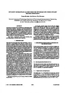
6. Performance Comparison of Keccak, Skein & JH Figures 8 and 9 represent the performance comparison of 256-bit and 512-bit variants, respectively, in a graphical view based on our results. It is clear from the graphs that Keccak is far ahead of the other two candidates, on both Virtex-5 and Virtex-7, in terms of throughput (TP) and throughput per area (TPA) for both 256-bit and 512-bit variants. The difference is large for the 256-bit variant; however, in the case of the 512-bit variants, the performance of JH and Skein is nearer to Keccak. For 256-bit variants, JH gives better throughput per area performance than Skein. In terms of area consumption, Skein leads all of the other candidates by consuming less area for the 256-bit variants, while for the 512-bit variants, the area consumption by JH is lower.
54
Kundi et al.
16000
Keccak-256
14000
JH-256
12000
Skein-256
10000 8000 6000 4000 2000 0 Area
TP
TPA
Area
Virtex 7
TP
TPA
Virtex 5
FIGURE 8. Performance comparison of 256-bit variants of SHA-3 finalists
8000
Keccak-512
7000
JH-512
6000
Skein-512
5000 4000 3000 2000 1000 0 [Slices]
[Mbps]
[Kbps/Slice]
[Slices]
[Mbps]
[Kbps/Slice]
Area
TP
TPA
Area
TP
TPA
Virtex 7
Virtex 5
FIGURE 9. Performance Comparison of 512-bit variants of SHA-3 Finalists
CUJSE 13, No. 1 (2016)
55
Hence, in a resource constrained environment, Skein (256-bit variants) is the better option because of its lower area consumption as compared to Keccak and JH, whereas for 512-bit variants, JH is compact. In terms of throughput, again Keccak is far ahead for 256-bit digest sizes. For TP and TPA, Skein is well behind the performances of Keccak and JH. Skein has computationally intensive designs as compared to other algorithms. If we consider throughput per area as the major deciding factor for performance comparisons, we can easily rank Keccak first followed by JH and Skein.
7. Conclusions In this work, we have presented efficient hardware implementations of Keccak as SHA-3, Skein and JH with respect to a unified architecture. Dedicatedly mapped LUT resources on FPGAs with a combination of Fast Carry Chain, MUXCY and XORCY are used to enhance the hardware performance of these cryptographic hash algorithms in terms of area. Reported implementation results of 256-bit and 512-bit variants of each algorithm on Xilinx Virtex-5 and Virtex-7 FPGA shows significant improvements in terms of area, throughput and throughput per area.
References [1] X. L. Xiaoyun Wang, D. Feng, H. Yu., Collisions for hash functions MD4, MD5, HAVAL-128 and RIPEMD. Cryptology ePrint Archive, Report 2004/199, (2004), 1-4. URL: http://eprint.iacr.org/2004/199 [2] M. Szydlo, SHA-1 collisions can be found in 263 operations, CryptoBytes Technical Newsletter, (2005). [3] M. Stevens, Fast collision attack on MD5. Cryptology ePrint Archive, Report 2006/104, (2006), 1-13, URL: http://eprint.iacr.org/2006/104.pdf [4] K. Aoki, J. Guo, K. Matusiewicz, Y. Sasaki, L. Wang, Preimages for Step-Reduced SHA2, In: Advances in Cryptology ASIACRYPT, Lecture Notes in Computer Science, 5912, Springer Berlin /Heidelberg, (2009), 578-597. [5] National Institute of Standards and Technology (NIST). SHA-3 Winner announcement, (2012), URL: http://www.nist.gov/itl/csd/sha-100212.cfm [6] I. F., Alshaikhli, M. A., Alahmad, K. Munthir, Comparison and Analysis Study of SHA-3 Finalists, International Conference on Advanced Computer Science Applications and Technologies, (2012), 366-371. [7] J. Daemen, V. Rijmen, The Design of Rijndael – AES Advanced Encryption Standard. Springer-Verlag Inc., New York USA (2002).
56
Kundi et al.
[8] Xilinx: 7 Series FPGAs Configurable Logic Block user guide. v1.7, Technical report (2014), URL: http://www.xilinx.com/support/documentation/user_guides/ug474_7Series_CLB.pdf [9] L. Henzen, P. Gendotti, P. Guillet, E. Pargaetzi, M. Zoller, F. K. Gurkaynak, Developing a hardware evaluation method for SHA-3 candidates, Proc. Cryptographic Hardware and Embedded Systems, (2010), 248-263. [10] S. Tillich, M. Feldhofer, M. Kirschbaum, T. Plos, J.-M. Schmidt, and A. Szekely, HighSpeed Hardware Implementations of Blake, Blue Midnight Wish, Cubehash, ECHO, Fugue, Grøstl, Hamsi, JH, Keccak, Luffa, Shabal, Shavite-3, SIMD, and Skein, Cryptology ePrint Archive, Report 2009/510, (2009), URL: http://eprint.iacr.org/2009/510.pdf [11] F. K. Gürkaynak, K. Gaj, B. Muheim, E. Homsirikamol, C. Keller, M. Rogawski, H. Kaeslin, J. -P. Kaps, Lessons Learned from Designing a 65nm ASIC for Evaluating Third Round SHA-3 Candidates, 3rd SHA-3 Candidate Conference, (2012), 1-21. [12] B. Jungk, M. Stöttinger: Among slow dwarfs and fast giants: A systematic design space exploration of KECCAK. 8th International Workshop on Reconfigurable and Communication-Centric Systems-on-Chip), (2013), 1-8. [13] S. Kerckof, F. Durvaux, N. Charvillon, F. Regazzoni, G. Meurice, F. Standaert, Compact FPGA Implementations of the Five SHA-3 Finalists, CARDIS 2011, LNCS, Springer Berlin Heidelberg, 7079, (2011), 217-233. [14] B. Jungk, Compact Implementations of Grøstl, JH and Skein for FPGAs, ECRYPT II Hash Workshop 2011, (2011), 1-15. [15] X. Guo, S. Huang, L. Nazhandali, P. Schaumont, On The Impact of Target Technology in SHA-3 Hardware Benchmark Rankings, Cryptology ePrint Archive, Report 2010/536, (2010), URL:http://eprint.iacr.org/2010/536.pdf [16] The SHA-3 Zoo Hardware Implementations, URL: http://ehash.iaik.tugraz.at/wiki/SHA3_Hardware_Implementations [17] B. Baldwin, N. Hanley, M. Hamilton, L. Lu, A. Byrne, M. Neill and W. P. Marnane, FPGA Implementations of the Round Two SHA-3 Candidates, 2nd SHA-3 Candidate Conference, (2010), 1-18. [18] S. Matsuo, M. Knezevic, P. Schaumont, I. Verbauwhede, A. Satoh, K. Sakiyama, K. Ota, How Can We Conduct Fair and Consistent Hardware Evaluation for SHA-3 Candidate? 2nd SHA-3 Candidate Conference, (2010), 1-15. [19] K. Gaj, E. Homsirikamol, M. Rogawski, R. Shahid, M. U. Sharif, Comprehensive evaluation of High Speed and medium speed implementations of five SHA-3 finalist using Xilinx and Altera FPGAs, 3rd SHA-3 Candidate Conference, (2012). [20] R. Shahid, M. U. Sharif, M. Rogawski, K. Gaj, Use of embedded FPGA resources in implementations of 14 round 2 SHA-3 candidates, IEEE International Conference on Field-Programmable Technology, (2011), 1-9.
CUJSE 13, No. 1 (2016)
57
[21] E. Homsirikamol, M. Rogawski, K. Gaj, Throughput vs. Area Trade-offs in High-Speed Architectures of Five Round 3 SHA-3 Candidates Implemented Using Xilinx and Altera FPGAs, Cryptographic Hardware and Embedded Systems, LNCS, Springer Berlin Heidelberg, 6917, (2011), 491-506. [22] E. Homsirikamol, M. Rogawski, K. Gaj, Comparing Hardware Performance of Round 3 SHA-3 Candidates using Multiple Hardware Architectures in Xilinx and Altera FPGAs, ECRYPT II Hash Workshop 2011, (2011), 1-15. [23] J. Strömbergson, Implementation of the Keccak Hash Function in FPGA Devices, (2008), 1-4, URL: http://www.strombergson.com/files/Keccak_in_FPGAs.pdf [24] A. Akin, A. Aysu, O. C. Ulusel, E. Savas, Efficient Hardware Implementations of High Throughput SHA-3 Candidates Keccak, Luffa and Blue Midnight Wish for Single- and Multi-Message Hashing, 2nd SHA-3 Candidate Conference, (2011). [25] M. Long, Implementing Skein Hash function on Xilinx Virtex-5 FPGA platform, (2009), URL: http://www.skein-hash.info/sites/default/files/skein_fpga.pdf [26] S. Tillich, Hardware implementation of the SHA-3 candidate Skein, Cryptology ePrint Archive, Report 2009/159, (2009), URL: http://www.eprint.iacr.org/2009/159.pdf [27] G. Bertoni, J. Daemen, M. Peeters, G. V. Assche, The Keccak SHA-3 Submission version 3, (2011), 1-14, URL: http://keccak.noekeon.org/Keccak-submission-3.pdf [28] K. Latif, A. Aziz, A. Mahboob, Optimal Utilization of Available Reconfigurable Hardware Resources, Elsevier Computer and Electrical Engineering, 37(6), (2011), 1043-1057. [29] N. Ferguson, S. Lucks, B. Schneier, D. Whiting, M. Bellare, T. Kohno, J. Callas, J. Walker, The Skein Hash Function Family Version 1.3, (2010), 1-100, URL: http://www.skein-hash.info/sites/default/files/skein1.3.pdf [30] H. Wu., The Hash Function JH, (2011), 1-54, URL: http://www3.ntu.edu.sg/home/wuhj/research/jh/jh_round3.pdf