Hindawi Publishing Corporation Journal of Electrical and Computer Engineering Volume 2016, Article ID 2374926, 12 pages http://dx.doi.org/10.1155/2016/2374926
Research Article Restoration of Partial Blurred Image Based on Blur Detection and Classification Dong Yang and Shiyin Qin School of Automation Science and Electrical Engineering, Beihang University, Haidian District, Beijing 100191, China Correspondence should be addressed to Dong Yang;
[email protected] Received 15 September 2015; Accepted 6 December 2015 Academic Editor: William Sandham Copyright © 2016 D. Yang and S. Qin. This is an open access article distributed under the Creative Commons Attribution License, which permits unrestricted use, distribution, and reproduction in any medium, provided the original work is properly cited. A new restoration algorithm for partial blurred image which is based on blur detection and classification is proposed in this paper. Firstly, a new blur detection algorithm is proposed to detect the blurred regions in the partial blurred image. Then, a new blur classification algorithm is proposed to classify the blurred regions. Once the blur class of the blurred regions is confirmed, the structure of the blur kernels of the blurred regions is confirmed. Then, the blur kernel estimation methods are adopted to estimate the blur kernels. In the end, the blurred regions are restored using nonblind image deblurring algorithm and replace the blurred regions in the partial blurred image with the restored regions. The simulated experiment shows that the proposed algorithm performs well.
1. Introduction Image deblurring is one of the most classical and challenging problems in image processing. There are several reasons which can cause blur. The first reason is the relative motion. If the object in the view field of the camera moves during the exposure, the images which the camera captured are motion blurred images. The object region in the image is motion blurred. The second reason is out of focus. If the object in the view field of the camera is not in the focus of the camera during exposure, the images which the camera captured are defocus blurred images. The object region in the image is defocus blurred. The third reason is the blending of the above two reasons. If the object in the view field of the camera moves during the exposure and the object is not in the focus of the camera, the images which the camera get are blend blurred images. The object region in the image is blend blurred. Based on the above analysis, we can find the blur is corresponding to the object; this results in the partial blurred image. The object regions in the image which satisfy one of the above three reasons are blurred. The other regions of the image are not blurred. It is a very challenging problem to restore the partial blurred image, because the blurred regions and the clear
regions coexist in one image. One solution is to restore the whole partial blurred image using the same blur kernel; this will cause unpleasant artifacts in the clear regions. Another possible solution to solve this problem is to detect the blurred regions in the partial blurred regions and then restore the blurred region using the image deblurring algorithm; this solution can avoid causing artifacts in the clear regions. The detection of the blurred regions in the partial blurred image is called blur detection. It is a very complex problem, and it is very important for partial blurred image restoration. Once the blurred region is extracted from the partial blurred image, the following problem is to estimate the blur kernels. For the defocus, motion, and blend blurred regions, their blur kernels can be expressed in mathematic model. They will be introduced in the following paragraph. If the blur class can be confirmed and the structure of the mathematical model is known, we just need to estimate the parameters of the model. But in many situations, the blur class which the blurred region belong to is not known. For example, we do not know whether the blurred region is a defocus blurred region, a motion blurred region, or a blend blurred region. The blur classification algorithm can solve this problem; it can classify the blurred region into a blur class. The proposed algorithm
2
Journal of Electrical and Computer Engineering
restores the partial blurred image using blur classification algorithm and blur detection algorithm. The blurring process can be shown as follows: 𝑦 = 𝑥 ⊗ 𝑘 + 𝑛,
(1)
where 𝑦 denotes blurred image, 𝑥 is the latent clear image, ⊗ denotes convolution operator, 𝑘 is blur kernel, and 𝑛 denotes noise. The blur kernels of the different kinds of blur are not the same. For instance, the mathematic model of motion blur is a line; it can be shown as follows: 1 { 𝐿 𝑘 (𝑥, 𝑦) = { {0
if √𝑥2 + 𝑦2 ≤ 𝐿, tan 𝜃 =
𝑦 𝑥
(2)
else,
where 𝑘 is blur kernel; the sum of all the elements of 𝑘 is 1. 𝑥 denotes the horizontal coordinate, 𝑦 means the vertical coordinate, 𝐿 is blur scale, and 𝜃 is blur angle. The mathematic model of defocus blur is a disk; it can be shown as follows: 1 { 𝑘 (𝑥, 𝑦) = { 𝜋𝑅2 {0
if 𝑥2 + 𝑦2 ≤ 𝑅2
(3)
else,
where 𝑅 is blur scale. The mathematic model of blend blur kernel is the convolution of the above two blur kernels. It can be shown as follows: 𝑘blend = 𝑘defocus ⊗ 𝑘motion .
(4)
Based on the above image blurring model, the image deblurring theories and algorithms developed very fast. In the beginning, the filter based image deblurring algorithms such as Wiener filter [1] are successfully used in image deblurring. The method can be shown as the following equation: ̂ (𝑢, V) = [ 𝐹
𝐻∗ (𝑢, V) ] 𝐺 (𝑢, V) , (5) |𝐻 (𝑢, V)|2 + 𝑆𝜂 (𝑢, V) /𝑆𝑓 (𝑢, V)
̂ V) denotes the Fourier transformation of the where 𝐹(𝑢, restored image; we can use inverse Fourier transformation to get the restored image; 𝐻∗ (𝑢, V) denotes the conjugation of the Fourier transformation of the blur kernel, 𝑆𝜂 (𝑢, V) is the power spectrum of the noise, and 𝑆𝑓 (𝑢, V) is the power spectrum of the blurred image. 𝐺(𝑢, V) denotes the Fourier transformation of the blurred image. Then, the regularization based image deblurring algorithms developed very fast; this kind of methods performs very well in image deblurring; it is still the mainstream of image deblurring algorithms. The basic idea of the regularization based algorithm is to construct a regularization term which can ensure the restored image satisfy a special condition. The construction of the regularization term is the key point of regularization based methods; the most famous regularization term is called TV (Total Variation) [2] which will be introduced in detail in the following paragraph. The regularization based image deblurring can be modeled as the following equation: 2 𝑥∗ = arg min [𝑥 ⊗ 𝑘 − 𝑦2 + 𝛼 (𝑥)] , 𝑥
(6)
where 𝑥∗ denotes the restored image. The first term is data fidelity term; the second term 𝛼(𝑥) is regularization term; it is a function of the latent clear image 𝑥. Given the mathematic model, we can get the restored image by solving (6). Some of the regularization terms are very complex; the analytic solutions of these methods are very hard to get, so the optimization technique is used to get an optimal solution. The construction of the regularization term and the methods to solve (6) are two most important key points. Most of the regularization based image deblurring algorithms are focused on solving these two problems. As the image deblurring technique developed, more complex image deblurring problems are proposed. The restoration of partial blurred image is one of them. This paper proposes a solution of this problem based on blur detection and classification.
2. Related Works Some regions of the partial blurred image may be blurred while the other regions remain clear. The restoration of this kind of complex blurred image is a very challenging problem. The solution for this problem contains two key points. The first is how to extract the blurred region from the partial blurred image which is called blur detection. The second is the classification of the extracted blurred region which is called blur classification. Blur detection and classification are two meaningful problems. If we can detect blur regions from a partial blurred image, some useful information can be extracted from the detection result; for example, the moving object often causes motion blur; it can be extracted from the detected blurred regions. The blur classification also brings out meaningful results. The kernel structure is corresponding to their blur class. Some algorithms can get the depth information from the defocus blurred image [3]. Liu et al. [4] propose a blur detection algorithm which performs well in blur detection. In their method the local power spectrum slope is adopted to describe the frequency domain feature. The gradient histogram span is used to describe the time domain feature. The maximum saturation is also adopted. Shi et al. [5] brought out a new blur detection algorithm which is based on the effective features. Shi’s method performs well. The output of their detection algorithm is an image; the pixel value of each point is corresponding to a score; this score is a measure which can describe the probability that this point belongs to blur class or clear class. But there are some wrong classified points whose scores are not corresponding with their blur class in their detection results. The blurred regions in the partial blurred images often correspond to a specific object, for example, a ball. If there are wrong classified points in the ball area, we cannot extract the entire ball area from the partial blurred images. The colors of the points in the same blurred area are often the same, so image segmentation algorithm can be adopted to improve the result. The details will be introduced in the following paragraphs. We propose a new blur detection algorithm based on image segmentation to improve the detection result.
Journal of Electrical and Computer Engineering
3
Kernel estimation of motion blur Partial blurred image
Blur detection
Feature extraction
Blur classification based on SVM
Kernel estimation of defocus blur
Restoration processing of partial blurred image
Recombination of partial restored image
Restored result
Kernel estimation of blend blur
Figure 1: The diagram of restoration scheme.
The image gradient distribution is a very important feature to classify different kinds of image. A new generalized Gaussian distribution which is proposed in [6] is adopted to describe the gradient distribution. It is successfully used in image processing. For the defocus blur, the blur kernel affects the gradient distribution of the blurred image in all the directions in the same manner, while the motion blur kernel affects the gradient distribution of the blurred image in all the directions in different manners. For the direction of the blur kernel, the gradient distribution is affected more seriously than the other directions. So we use it to describe the different kinds of blur. In order to classify the different kinds of blurred images more precisely, the image frequency domain feature needs to be added to the final classification framework. So the Radon transformation is adopted. The Radon transformation of an image is its projection along a direction. For different blurred images, their Fourier transformation images are different. This is because the convolution in the time domain is equal to multiplication in frequency domain. The convolution of clear image and blur kernel is converted into the multiplication of the Fourier transformation of the clear image and the Fourier transformation of the blur kernel. The different blur kernels will affect the blurred images in different way. In order to describe the difference, the Radon transformation of the Fourier transformation is also used to classify the different kinds of blur. After the blur class of the extracted blurred region is confirmed, the following procedure is the blur kernel parameter estimation. The cepstrum is adopted to estimate the parameters. In the end, the nonblind image deblurring algorithm is adopted to restore the blurred region.
3. Restoration Strategy Based on Blur Detection and Classification 3.1. The Necessity of Detection and Classification of Blurred Regions. The difficulty of restoring the partial blurred image is obvious. It contains clear regions and blurred regions. If the whole image is considered to be a blurred image, the blur kernel estimated from this image is obviously not suitable. If the whole image is considered to be clear image, it is not suitable too. So the clear regions and the blurred regions should be processed in different way. The strategy is to detect the blurred regions and restore them while keeping the other clear regions unchanged.
3.2. The Restoration Scheme Based on Blurred Regions. Given a partial blurred image, the blur detection algorithm is adopted to detect the blurred regions; then the blur classification algorithm is adopted to classify the different blurs. The blur detection procedure is finished in a coarse to fine mode. Firstly we get the coarse detection result; then we use image segmentation to refine the detection result. The blur classification procedure includes two steps. The first step is feature extraction; the second step is the classification based on SVM (Support Vector Machine) [7, 8]. Then, the blur kernels are estimated from the blurred region. In the end, the final restored image is the recombination of the restored version of the blurred region and the clear regions. Figure 1 is the flow chart of the proposed algorithm.
4. The Algorithm Based on Blur Detection and Classification 4.1. Blur Detection Based on Image Segmentation 4.1.1. The Scheme of Blurred Regions Detection. At first, Shi’s method [5] is adopted to get the coarse detection result; meantime, the mean shift based image segmentation algorithm is adopted [9] to segment the image into regions. After that, the region based blur detection is adopted to refine the detection result. In the end, each region is compared with its neighbour regions; if all the neighbour regions are different, the region is considered to be the same with its neighbour regions. For example, if one region is classified into clear class while all the neighbour regions are classified into blur regions, the region is considered to be blurred region. This procedure can refine the detection result. The flow chart is shown in Figure 2. 4.1.2. Initial Blur Detection Using the Algorithm Proposed in [5]. Shi’s algorithm [5] performs well in blur detection, so it is adopted to get the coarse detection result. The pixel value of each point in their result image is corresponding to the blur degree. If the pixel value is close to 255, the pixel is considered to be very close to a blur pixel. If the pixel value is close to 0, the pixel is considered to be very close to a clear pixel. For each pixel, its pixel value is compared with a threshold 𝜀. If it is the bigger one, it is considered to be a blurred pixel. If it is the smaller one, it is considered to be a clear pixel. The key point of the success of Shi’s method is that the feature used in the algorithm is very effective.
4
Journal of Electrical and Computer Engineering
Initial blur detection
Partial blurred image
Blur detection based on image segmentation
Detection result
Image segmentation
Figure 2: The flow chart of blurred regions detection.
The feature consists of the peakedness measure, sum of power spectra, heavy-tailedness measure, and local filters. The mathematic model of the peakedness measure is as follows: 𝐾 (𝑎) =
𝐸 [𝑎2 ] 𝐸2 [𝑎4 ]
− 3,
(7)
where 𝑎 denotes gradient distribution. 𝐸[⋅] is expectation operator. This feature can describe the peakedness of a gradient distribution. Another feature which is related to gradient distribution is heavy-tailedness measure. It includes two features; the first one can be shown as follows: 𝑓1 = min (ln (𝐾 (𝐵𝑥 ) + 3) , ln (𝐾 (𝐵𝑦 ) + 3)) ,
(8)
where 𝐵𝑥 denotes horizontal gradient distribution and 𝐵𝑦 denotes vertical gradient distribution; another feature can be shown as follows: 𝑓2 = 𝜎1 subject to
∇𝐼
(9)
≅ 𝜋1 𝐺 (∇𝐼 | 𝜇1 , 𝜎1 ) + 𝜋2 𝐺 (∇𝐼 | 𝜇2 , 𝜎2 ) , where ∇𝐼 is a gradient distribution, 𝐺(⋅) is a Gaussian distribution, 𝜇 is the mean value of the Gaussian distribution, and 𝜎 is the variance of the Gaussian distribution. This is a typical Gaussian mixture model which contains two components. The variance of the first component is treated as another feature. The mathematic model of the sum of averaged power spectra is shown as follows: 𝑓3 = ∑ log (𝐽 (𝜔)) 𝜔
𝐽 (𝜔) =
1 ∑𝐽 (𝜔, 𝜃) , 𝑛 𝜃
(10)
where 𝐽 means the Fourier transformation in polar coordinate; (𝜔, 𝜃) is the polar coordinate of a pixel. It is another feature. The local filters are a series of filters which can separate the blurred image patches and clear image patches. They are learned using the blurred image patches and clear image patches. The local filter features can be shown as follows: 𝑓4𝑛 = {𝑤1𝑇 𝐵, . . . , 𝑤𝑛𝑇 𝐵} ,
where 𝑤𝑖𝑇 (𝑖 = 1, . . . , 𝑛) denotes the local filters and 𝐵 denotes the image patches. Based on the above features, the naive Bayesian classifier is adopted to classify the image pixels into blurred or nonblurred.
(11)
4.1.3. Image Segmentation Based on Mean Shift. The mean shift image segmentation algorithm performs well in image processing and computer vision; it is based on the color information. The basic idea of mean shift is that the position of an image point in the feature space is changed step by step until satisfying a condition. The mean shift vector consists of the move direction and step length for each step; it is shown as equation (14). The probability density function used in the mean shift algorithm can be shown as the following equation: 𝑛 2 ̂ (𝑥) = 𝑐𝑘,𝑑 ∑𝑘 ( 𝑥 − 𝑥𝑖 ) , 𝑓 ℎ,𝐾 𝑑 𝑛ℎ 𝑖=1 ℎ
(12)
̂ (𝑥) denotes the probability density function of an where 𝑓 ℎ,𝐾 image, 𝑥 denotes a point in an image, 𝑑 is the dimension of the image, 𝑐𝑘,𝑑 is a constant, and ℎ is the size of the window whose centre is the pixel 𝑥. 𝑘(⋅) denotes the kernel function; it has different forms; the most popular kernel function is the Gaussian kernel function. 𝑥𝑖 denotes the 𝑖th neighbour point in a window whose centre is the pixel 𝑥. In order to get the maximum of the above equation, the gradient of the probability function should be computed; it is shown as the following equation: ̂ (𝑥) = ∇𝑓 ℎ,𝐾
𝑛 𝑥 − 𝑥𝑖 2 2𝑐𝑘,𝑑 )] [ 𝑔 ( ∑ 𝑛ℎ𝑑+2 𝑖=1 ℎ
2 ∑𝑛𝑖=1 𝑥𝑖 𝑔 ((𝑥 − 𝑥𝑖 ) /ℎ ) ] [ ⋅ 2 − 𝑥 , ∑𝑛𝑖=1 𝑔 ((𝑥 − 𝑥𝑖 ) /ℎ ) ] [
(13)
where 𝑔(𝑥) = −𝑘 (𝑥); if the Gaussian kernel function is adopted, the new position of point 𝑥 in the iteration is as follows: 𝑥=
2 ∑𝑛𝑖=1 𝑥𝑖 𝑔 ((𝑥 − 𝑥𝑖 ) /ℎ ) 2 . ∑𝑛𝑖=1 𝑔 ((𝑥 − 𝑥𝑖 ) /ℎ )
(14)
It is the weighted mean value of the points in a window, so it is called mean shift algorithm.
Journal of Electrical and Computer Engineering
(a)
(b)
5
(c)
(d)
(e)
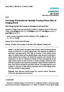
Figure 3: Results of blur detection. (a) Partial blurred images. The train in the centre of the image which lies in the first row is blurred artificially using 8-pixel 0-degree motion blur kernel; the other regions are clear regions. The plaque in the centre of the image which lies in the second row is blurred artificially using 8-pixel defocus blur kernel; the other regions are clear regions. The guideboard in the centre of the image which lies in the third row is blurred artificially using a blend blur kernel whose motion blur scale and defocus blur scale are 5 pixels and motion direction is 0 degrees; the other regions are clear regions. (b) Shi’s results. (c) Segmentation results. (d) Detection results based on image segmentation. (e) Final results after refining based on neighbour information.
4.1.4. Blur Detection Based on Image Segmentation. For each region of the partial blurred image, we count the number of the blurred points and the number of the points in the region; if this ratio exceeded a threshold, this region is treated as a blurred region. Thus, the decision rule is shown as follows: If 𝑏𝑖 /𝑁𝑖 > 𝜆 then 𝑆𝑖 is a blurred segment, where 𝑆𝑖 is the 𝑖th region, 𝑁𝑖 is the number of the points in the 𝑖th region, and 𝑏𝑖 is the number of the blurred pixels. The ratio 𝑏𝑖 /𝑁𝑖 can describe the blur degree of region 𝑆𝑖 . If it exceeded the threshold 𝜆, the segment 𝑆𝑖 is treated as a blurred region; the pixel value of the points in 𝑆𝑖 is set at 1, or it is set at 0. There are some small wrong classified regions in the detection result; in order to improve the detection result, we make use of the neighbor information of each region to refine the detection result. For each region, we find all its neighbor regions; if the neighbor regions are all classified into blurred class, this region is considered to be a blurred region. Otherwise, it remains unchanged. The results of the blur detection algorithm are shown in Figure 3. From the results we can find there are many wrong classified points in the results of the initial detection. If the blurred region is extracted from the partial blurred
image based on the initial detection result, many important details will be lost. The results of the detection based on segmentation show that the proposed algorithm overcomes this shortcoming. The detection results do not contain isolated wrong classified points, but there are some wrong classified regions in the detection result. The wrong classified region is refined after the neighbour refining procedure. The final results show that the proposed algorithm extracts the blurred regions successfully. The details of the algorithm are shown in Algorithm 1. 4.2. Blurred Regions Feature Extraction and Classification. The detected blurred regions are classified into the correct class using the proposed blur classification algorithm. For each detected blurred region, the feature is extracted from it; then the detected blurred region is classified into a class using the trained SVM based classifier. The features include the gradient feature, Radon transformation feature, and edge features of the Fourier transformation. The classification procedure includes two steps. In the first step, the blurred regions are classified as defocus blur or nondefocus blur. In the second step, the nondefocus blur is classified into motion blur or blend blur. The flow chart is shown in Figure 4.
6
Journal of Electrical and Computer Engineering
Input: blurred image with partial blurred regions 𝑦, threshold 𝜆, threshold 𝜀. Output: final blur detection result 𝑆 𝐷 = InitialDetection(𝑦); % Initial blur detection 𝑆 = MeanShift(𝑦); % Color segmentation % Segmentation Based Detection For 𝑘 = 1 to 𝑁, % The number of the segments 𝑏𝑘 = 0; 𝑁𝑘 = 0; For 𝑗 = 1 to 𝑀 % The points of a segment If 𝐷(𝑘, 𝑗) > 𝜀 % The 𝑗th point in segment 𝑘 𝑏𝑘 = 𝑏𝑘 + 1; End If 𝑁𝑘 = 𝑁𝑘 + 1; End for If 𝑏𝑘 /𝑁𝑘 > 𝜆 𝑆(𝑘) = 1; Else 𝑆(𝑘) = 0; End If End For % Neighbour Refine For 𝑖 = 1 to 𝑁, % The number of segments 𝐶 = 0; For 𝑗 = 1 to 𝑀 % The number of the neighbours 𝐶 = 𝐶 + 𝑆(𝑗) End If 𝐶/𝑀 = 1 and 𝑆(𝑖) = 0 𝑆(𝑖) = 1; Else if 𝐶/𝑀 = 0 and 𝑆(𝑖) = 1 𝑆(𝑖) = 0; End If end Algorithm 1: Blur detection algorithm.
Nondefocus blur
Image gradient estimation
Line feature extraction
SVM based classification
Blurred regions Radon transformation
Motion blur
Logarithm Fourier transformation
SVM based classification Circle feature extraction
Blend blur
Defocus blur
Figure 4: The flow chart of blur classification.
4.2.1. Feature Extraction. The key to classify the different kinds of blur is the feature. For the different kinds of blur, their gradient distribution is different and the Fourier transformation of the different kinds of blurred regions is also different. So these two kinds of features are adopted to describe the difference. The specific mathematic model of the features will be introduced in detail in the following paragraph. The generalized Gaussian distribution [6] is adopted to fit the gradient distribution. It can be shown as the following
equation: 𝑓 (𝑥; 𝛼, 𝜎2 ) =
𝛼 𝛼 |𝑥| exp (− ( ) ) 2𝛽Γ (1/𝛼) 𝛽
𝛽 = 𝜎√ ∞
Γ (1/𝛼) Γ (1/𝛼)
Γ (𝑎) = ∫ 𝑡𝑎−1 𝑒−𝑡 𝑑𝑡 0
(15) 𝑎 > 0,
Journal of Electrical and Computer Engineering
7
where 𝛼 denotes the mean and 𝜎 denotes the variance. The mean 𝛼 and the variance 𝜎 of the distribution are treated as two features. The means and variances of the gradient distributions in the four directions are treated as gradient distribution features. The four directions include the vertical, positive diagonal, horizontal, and negative diagonal direction. For each direction, a generalized Gaussian distribution is adopted to fit the gradient distribution in this direction. The central area of the Fourier transformation image of the defocus blur image is a disk; the projections of the Fourier transformation image in each direction are similar. The Fourier transformation image of the motion blur images is different from the defocus blur image; there are line stripes in the Fourier transformation image. The projection of Fourier transformation image in each direction changes significantly. The Fourier transformation image of blend blur images not only has the feature of the motion blur images, but also has the feature of the defocus blur image. So the projection of the Fourier transformation can be used to describe the difference of the different blur. The Radon transformation [10] can describe this feature. It can be shown in the following equation: 𝑅 (𝑓) (𝜃) =∫
+∞
−∞
𝑓 (𝑥 cos 𝜃 − 𝑦 sin 𝜃, 𝑥 sin 𝜃 − 𝑦 cos 𝜃) 𝑑𝑦 ,
(16)
𝑥 cos 𝜃 sin 𝜃 𝑥 ][ ], [ ] = [ − sin 𝜃 cos 𝜃 𝑦 𝑦 where 𝑅(𝑓)(𝜃) denotes the Radon transformation. 𝑥 and 𝑦 are the horizontal and vertical coordinates of an image. 𝜃 is the direction of the Radon transformation. Equation (16) indicates that the Radon transformation is the sum of images along the direction 𝜃. The Radon transformation is basically the projection in the direction 𝜃. Instead of computing the Radon transformation of the original image, we compute the Radon transformation of the Fourier transformation image in all the directions which range from 0 to 179 degrees. After that, we compute the variance of the Radon transformation in each direction. Finally, we construct the feature using the biggest variance and the smallest variance. The mathematic model is shown as follows: 𝑓𝑟 2
=
2
max (Var (𝑅 (𝑓) (𝜃))) − min (Var (𝑅 (𝑓) (𝜃))) 2
max (Var (𝑅 (𝑓) (𝜃)))
,
(17)
where Var(⋅) is the variance of the Radon transformation in all directions, max(⋅) is the biggest value of Var(⋅), and min(⋅) is the smallest value of Var(⋅). The lines can be detected in the Fourier transformation image of the motion blurred images using edge detector and Hough transformation. The circles can be detected in the Fourier transformation image of the defocus blurred images using edge detector [11] and Hough transformation [12].
The circles and lines can be detected in the Fourier transformation image of the blend blurred images. The ratio of the edge points which lie in the fitted line or circle and the number of the edge points are treated as the other two features. They are shown as the following equation: 𝑓𝑙 =
𝑛𝑒𝑙 , 𝑛𝑒
𝑓𝑐 =
𝑛𝑒𝑐 , 𝑛𝑒
(18)
where 𝑓𝑙 is the line feature, 𝑓𝑐 is the circle feature, 𝑛𝑒𝑙 is the number of the edge points which are in the fitted line, 𝑛𝑒𝑐 denotes the number of the edge points which are in the fitted circle, and 𝑛𝑒 denotes the number of the edge points. If the detected blurred region is not a geometrically regular one, the maximum inscribed rectangle of the detected blurred region is used to represent the detected blurred region. The Fourier transformation based and Radon transformation based features are extracted from the maximum inscribed rectangle of the detected blurred region. 4.2.2. Blurred Regions Classification Based on SVM. The SVM [7, 8] performs very well in image processing and image classification. The LIBSVM [13] is adopted to classify the blurred regions. Given some samples (𝑥𝑖 , 𝑦𝑖 ) (𝑖 = 1, . . . , 𝑁), 𝑤 denotes the separation hyperplane; the equation which the hyperplane should satisfy is shown as follows: 𝑦𝑖 (𝑤𝑇 𝑥𝑖 + 𝑏) ≥ 1 − 𝜉𝑖 ,
(19)
where 𝑏 denotes the deviation. 𝜉𝑖 denotes slack variable. The optimal separation hyperplane 𝑤 can be obtained by solving the following equation: 𝑁 1 Φ (𝑤, 𝜉) = 𝑤𝑇 𝑤 + 𝐶∑𝜉𝑖 , 2 𝑖=1
(20)
where 𝐶 denotes the penalty parameter. The equation can be transformed into the following equation: 𝑁 1𝑁 𝑁 𝑄 (𝛼) = ∑𝛼𝑖 − ∑∑𝛼𝑖 𝛼𝑗 𝑦𝑖 𝑦𝑗 𝐾 (𝑥𝑖 , 𝑥𝑗 ) 2 𝑖=1𝑗=1 𝑖=1 𝑁
∑𝛼𝑖 𝑦𝑖 = 0, 𝑖=1
(21)
𝛼𝑖 ≥ 0,
where 𝐾 is the kernel function. The final classifier can be obtained by solving (20): 𝑁
𝑓 (𝑥) = sgn [∑𝛼𝑖 𝑦𝑖 𝐾 (𝑥𝑖 , 𝑥) + 𝑏] ,
(22)
𝑖=1
where 𝑏 denotes the classification threshold and 𝛼𝑖 denotes the solution of (20).
8
Journal of Electrical and Computer Engineering
Input: sample images 𝑦𝑠 (𝑠 = 1, . . . , 𝑁), blurred image 𝑦 Output: blur class 𝑐 of 𝑦 Step 1: Feature Extraction % Gradient feature extraction 𝑓𝑔 = GGD(𝑦𝑠 ); FT = log 10 (1 + fftshift(abs(Fourier(𝑦𝑠 )))); % Fourier transformation 𝑓𝑟 = Radon(FT); % Radon transformation feature edge = Canny(FT); % Compute the edge of FT % Extract the line feature 𝑓𝑙 = Houghline(edge); 𝑓𝑐 = Houghcirle(edge): % Extract the circle feature Feature normalization; Step 2: SVM Traning SVM1 = Svmtrain(𝑓𝑔 , 𝑓𝑟 ); % SVM1 Training % SVM2 Training SVM2 = Svmtrain(𝑓𝑙 , 𝑓𝑐 ); Step 3: Classification Feature Extraction of y as Step 1; defocus = SVM1 (𝑓𝑔 , 𝑓𝑟 ); % SVM1 prediction If defocus = 1 c = defocus; exit; Else motion = SVM2 (𝑓𝑙 , 𝑓𝑐 ); % SVM2 prediction If motion = 1 c = motion; exit; Else c = blend; exit; End If End If Algorithm 2: Blur classification algorithm.
In order to train and test the SVM based classification algorithm, clear images are adopted to generate 150 sample blurred images which include the motion, defocus, and blend blurred images. Each kind of blurred images is a third of the sample images. Half of the sample images are adopted to train the classifier; another half of sample images are used to test the classifier. The recognition rate is 98 percent for the first classifier. The recognition rate is 97 percent for the second. The details are shown in Algorithm 2. 4.3. Blur Kernel Parameter Estimation and Blurred Image Restoration. The parameter estimation algorithm can be categorized as two classes. The first class is the direct estimation algorithm. It consists of two algorithms. The first algorithm is based on the geometry structure of the Fourier transformation image of the blurred image. We can detect line or circle in the motion blurred or defocus blurred images. The distance between the detected lines can be used to determine the motion blur scale; the defocus blur scale can be determined using the radius of the detected circle in the Fourier transformation image of the blurred image. This method relies on the accuracy of the detected line or circle; if the detected line or circle is not correct which often occurs because of the noise of the Fourier transformation, the estimated blur kernel parameter is not accurate. So the robustness of this method is not good. The second
algorithm of the direct estimation algorithm is to estimate the blur kernel parameters based on the negative peakedness of the cepstrum. This method performs well in parameter estimation task. So it is adopted to estimate the defocus blur and motion blur parameters. The blur parameters of the blend blur are very hard to estimate; we use the method proposed in [14] to estimate the blend blur kernel. The second class is searching based algorithm. This kind of method searches for the best blur kernel parameter which satisfies a special condition. The condition may be a quality measure which can measure the quality of the restored image using a specific blur parameter. In this paper, we use the cepstrum based algorithm and searching based algorithm to estimate the blur parameter and chose the better parameter to do the restoration procedure. 4.3.1. Parameter Estimation Based on Cepstrum. The mathematic model of the cepstrum is as follows: ̂𝑐 (𝑥, 𝑦) = 𝐹−1 (ln |𝐶 (𝑢, V)|) ,
(23)
where 𝐶(𝑢, V) is the Fourier transformation of an image 𝑐(𝑥, 𝑦). The cepstrum was successfully used in blur kernel parameter estimation. So it is adopted to estimate the blur kernel parameters.
Journal of Electrical and Computer Engineering
9
Input: Blurred images 𝑦 Output: blur scale 𝑠 of 𝑦 For i = 6 : 20 % restore 𝑦 using kernels 𝑟𝑦𝑖 = deconvolution(𝑦, 𝑘𝑖 ) end For i = 6 : 20 % measure the restored image 𝑚𝑖 = BRISQUE(𝑟𝑦𝑖 ) end 𝑠 = subscript (biggest(𝑚)) % find the biggest value in 𝑚 Algorithm 3: Searching algorithm.
For defocus blurred images, the location of the negative peakedness of the cepstrum is the defocus scale. For motion blurred images, the location of the negative peakedness of the cepstrum is the motion blur scale. The location of the negative peakedness and the origin of coordinate can confirm a line; the angle of this line can be used to determine the blur angle. In the experiment, we find this method is not stable in estimating the motion blur angle. We proposed an improved method to estimate the blur angle and use the cepstrum based method to estimate the motion blur scale. The method to estimate the motion blur angle is based on the Fourier transformation image of the blurred image. We compute the variance of the Radon transformation of the Fourier transformation image in each direction; then the direction which is corresponding to the biggest variance is considered to be the blur angle. The results of the cepstrum based estimation algorithm for a test image is shown in Figure 5. The results show the cepstrum based algorithm can effectively estimate the blur parameters. 4.3.2. Parameter Estimation Using Searching Algorithm. Firstly, the basic idea of this algorithm is introduced. For a defocus blurred image, the possible blur kernels whose blur scale ranged from 6 to 20 pixels are used to restore the blurred image separately; then the image quality assessment method BRISQUE [6] is adopted to measure the quality of the fifteen restored images. The restored image which is corresponding to the highest score is considered to be the best restored image. The blur kernel parameter which is used to restore this best restored image is considered to be the blur kernel parameter of this blurred image. Here, we consider the blur scale ranges from 6 to 20. For a motion blurred image, we use the Radon transformation based method proposed in the above cepstrum based parameter estimation paragraph to estimate the blur angle. Then, we use the same method to estimate the motion blur scale as the method used to estimate the defocus blur scale. The details are shown in Algorithm 3. The key point for this algorithm is the image quality assessment measure. Here the BRISQUE is adopted to measure the image quality. The BRISQUE is a very effective image quality assessment measure. The authors in [6] use asymmetric generalized Gaussian distribution (AGGD) to model the image and construct feature space using the parameters of the AGGD. In the end, they learn a mapping from the feature to the quality score.
4.3.3. Image Restoration Based on TV. Once the blur kernel is known, the gradient descent based TV [15] is adopted to restore the image. Its mathematic model is as follows: 2 𝑥∗ = arg min {𝑥 ⊗ 𝑘 − 𝑦 + 𝛼∑√‖∇𝑥‖2 + 𝛽2 } , 𝑥
𝑥
(24)
where ∇𝑥 denotes the gradient of 𝑥. 𝛼 denotes the regularization parameter. 𝛽 denotes the regularization parameter for the regularization term. The gradient descent algorithm is adopted to solve the equation; the iteration solution of (24) is as follows:
𝑥(𝑘+1) = 𝑥(𝑘) − 𝜏 (𝑘𝑇 ⊗ (𝑘 ⊗ 𝑥(𝑘) − 𝑦) (25) − 𝛼div (
∇𝑥(𝑘) )) , √∇𝑥(𝑘) 2 + 𝛽2
where div(⋅) denotes the divergence operator; 𝜏 denotes the step size which is a constant. 𝑇 is a transpose operator. The restoration results are shown in Figure 6. 4.4. Recombination Based on Region Detection Information. After we get the restored version of the burred region. The restored region and the clear regions of the image should be recombined to construct the final restored image. The recombination strategy is to replace the blurred region with its restored version directly. But, there is a problem; if we restore the detect blurred region and replace it with its restored version directly, it will cause unpleasant artifacts in the junction of the restored region and the clear regions. The reason is that the restore algorithm often causes this kind of artifacts in the border of the restored image. In order to solve this problem, we extend the border of the original detected blurred region to construct a new blurred region. After the restoration procedure, we replace the detected blurred area with its corresponding restored area in the extend restored region. Thus the artifacts in the border are avoided by extending blurred region.
10
Journal of Electrical and Computer Engineering
Estimated defocus scale result
20
Estimated defocus scale (pixel)
18 16 14 12 10 8 6 6
8
10
12
14
16
18
20
True defocus scale (pixel) True defocus scale Estimated defocus scale (a)
(b)
Estimated motion scale result
20
80
18
70 16
Estimated angle (deg.)
Estimated motion scale (pixel)
Estimated angle result
90
14 12 10
60 50 40 30 20
8
10
6 6
8
10 12 14 16 True motion scale (pixel)
True motion scale Estimated motion scale (c)
18
20
0 10
20
30
40 50 True angle (deg.)
60
70
80
True angle Estimated angle cepstrum Estimated angle Radon (d)
Figure 5: The estimation result of the cepstrum based estimation method. (a) is the original image used to test the cepstrum based blur kernel estimation algorithm. (b) is the defocus blur scale estimation result. The test images are generated using the original clear image and the defocus blur kernels whose scale ranges from 6 to 20. The red line is the defocus blur scale of the test images; the green line is the estimated blur scale using the cepstrum based algorithm. (c) is the result of the motion blur scale estimation results. The test images are generated using the original clear image and the motion blur kernels whose scale ranges from 6 to 20. The angle of the motion blur kernels is set at 30 degrees in order to test the motion blur scale estimation algorithm. The red line is the motion blur scale of the test images; the green line is the estimated motion blur scale. (d) is the motion blur angle estimation results. The test images are generated using the original clear image and motion blur kernels whose angles range from 10 to 80 degrees. The blur scale of the motion blur kernel is set at 8 pixels in order to test the motion blur angle estimation algorithm. The red line is the motion blur angle of the test images, the green line is the motion blur angle estimation algorithm based on cepstrum, and the blue line is the improved estimation algorithm based on Radon transformation.
Journal of Electrical and Computer Engineering
(a)
(b)
11
(c)
(d)
(e)
Figure 6: Comprehensive experiment. (a) The upper image is the extracted blurred region from Figure 3(a); the under image is its restored version. (b) The estimated blur kernel. (c) Final result. (d) Result using the same blur kernel for the whole image. (e) The upper images are the detailed images of (c); the lower images are the detailed images of (d).
5. Comprehensive Experiments and Comparative Analysis Figure 6 is the results of the proposed algorithm. The test partial blurred images are degraded images as shown in Figure 3(a). Firstly the blurred regions are detected using the proposed algorithm; the detection results of the proposed detection results are shown in Figure 3(e). Then the blurred region in the first row of Figure 6 is classified as defocus blur using the proposed blur classification algorithm. The blurred region in the second row is classified as motion blur. The blurred region in the third row is classified as blend blur. After that, the blur kernel parameters are estimated using the mentioned method. The estimated blur kernel parameter for the first row of Figure 6 is a 8-pixel defocus blur kernel using the cepstrum based algorithm. The result of the searching algorithm is a 10-pixel defocus blur kernel. The estimated blur kernel parameter of the second row based on the cepstrum algorithm is a 9-pixel 0-degree motion blur kernel. The estimated blur kernel parameter of the second row using searching algorithm is a 6-pixel 0-degree motion blur kernel. The estimated blur kernel of the third row is the result of the method proposed in [14]. So we use the estimated blur kernels based on cepstrum to restore the blurred image.
In the end the TV based image deblurring algorithm is adopted to restore the blurred regions and replace the blurred regions with the restored region. Thus, we get the final restoration results. The upper images of Figure 6(a) are the extracted blurred regions; the lower images of Figure 6(a) are the restored regions. The restored region contains many details which are lost in the original blurred image. The restoration algorithm performs very well; the reason is that the blur kernel is estimated correctly. The lower images of Figure 6(e) include many artifacts while the upper images of Figure 6(e) keep the original structure. These results show that the proposed method performs better than the restoration method which uses the same blur kernel for the whole image with partial blurred regions. The blur kernel used for the whole image is the same as the estimated blur kernel from the blurred region using the proposed algorithm. The restoration algorithm for the whole image is TV.
6. Conclusion The new restoration algorithm for partial blurred images proposed in this paper provides an effect solution to handle the restoration problem for partial blurred images.
12 The proposed algorithm consists of an effective blur detection algorithm and an effective blur classification algorithm. The results show that the proposed algorithm performs well in partial blurred image restoration. In the future, the proposed algorithm can be improved in several aspects, such as finding more features for blur classification. An early version [16] of this paper was presented at the IEEE International Conference on Mechatronics and Automation (ICMA 2015).
Conflict of Interests The authors declare that there is no conflict of interests regarding the republication of this paper.
Acknowledgment This work was partly supported by National Natural Science Foundation of China (Grants nos. 61273350 and U1435220).
References [1] R. C. Gonzalez, Digital Image Processing, Prentice Hall, Upper Saddle River, NJ, USA, 2nd edition, 2002. [2] L. I. Rudin, S. Osher, and E. Fatemi, “Nonlinear total variation based noise removal algorithms,” Physica D: Nonlinear Phenomena, vol. 60, no. 1–4, pp. 259–268, 1992. [3] P. Favaro and S. Soatto, “A geometric approach to shape from defocus,” IEEE Transactions on Pattern Analysis and Machine Intelligence, vol. 27, no. 3, pp. 406–417, 2005. [4] R. Liu, Z. Li, and J. Jia, “Image partial blur detection and classification,” in Proceedings of the 26th IEEE Conference on Computer Vision and Pattern Recognition (CVPR ’08), pp. 1–8, IEEE, Anchorage, Alaska, USA, June 2008. [5] J. Shi, L. Xu, and J. Jia, “Discriminative blur detection features,” in Proceedings of the 27th IEEE Conference on Computer Vision and Pattern Recognition (CVPR ’14), pp. 2965–2972, IEEE, Columbus, Ohio, USA, June 2014. [6] A. Mittal, A. K. Moorthy, and A. C. Bovik, “No-reference image quality assessment in the spatial domain,” IEEE Transactions on Image Processing, vol. 21, no. 12, pp. 4695–4708, 2012. [7] V. N. Vapnik, Statistical Learning Theory, Wiley-Interscience, New York, NY, USA, 1998. [8] J. S. Taylor and N. Cristianini, Kernel Methods for Pattern Analysis, Cambridge University Press, Cambridge, UK, 2004. [9] D. Comaniciu and P. Meer, “Mean shift: a robust approach toward feature space analysis,” IEEE Transactions on Pattern Analysis and Machine Intelligence, vol. 24, no. 5, pp. 603–619, 2002. [10] S. R. Deans, The Radon Transform and Some of Its Applications, Wiley-Interscience, New York, NY, USA, 1983. [11] J. Canny, “A computational approach to edge detection,” IEEE Transactions on Pattern Analysis and Machine Intelligence, vol. 8, no. 6, pp. 679–698, 1986. [12] P. V. C. Hough, “Methods and Means for Recognizing Complex Patterns,” U. S. Patent 3069654, December 18, 1962. [13] C.-C. Chang and C.-J. Lin, “LIBSVM: a Library for support vector machines,” ACM Transactions on Intelligent Systems and Technology, vol. 2, no. 3, article 27, 2011.
Journal of Electrical and Computer Engineering [14] D. Krishnan, T. Tay, and R. Fergus, “Blind deconvolution using a normalized sparsity measure,” in Proceedings of the IEEE Conference on Computer Visionand Pattern Recognition (CVPR ’11), pp. 233–240, Colorado Springs, Colo, USA, June 2011. [15] G. Peyr´e, “The numerical tours of signal processing,” Computing in Science & Engineering, vol. 13, no. 4, Article ID 5931491, pp. 94–97, 2011. [16] D. Yang and S. Qin, “Restoration of degraded image with partial blurred regions based on blur detection and classification,” in Proceedings of the IEEE International Conference on Mechatronics and Automation (ICMA ’15), pp. 2414–2419, IEEE, Beijing, China, August 2015.
International Journal of
Rotating Machinery
Engineering Journal of
Hindawi Publishing Corporation http://www.hindawi.com
Volume 2014
The Scientific World Journal Hindawi Publishing Corporation http://www.hindawi.com
Volume 2014
International Journal of
Distributed Sensor Networks
Journal of
Sensors Hindawi Publishing Corporation http://www.hindawi.com
Volume 2014
Hindawi Publishing Corporation http://www.hindawi.com
Volume 2014
Hindawi Publishing Corporation http://www.hindawi.com
Volume 2014
Journal of
Control Science and Engineering
Advances in
Civil Engineering Hindawi Publishing Corporation http://www.hindawi.com
Hindawi Publishing Corporation http://www.hindawi.com
Volume 2014
Volume 2014
Submit your manuscripts at http://www.hindawi.com Journal of
Journal of
Electrical and Computer Engineering
Robotics Hindawi Publishing Corporation http://www.hindawi.com
Hindawi Publishing Corporation http://www.hindawi.com
Volume 2014
Volume 2014
VLSI Design Advances in OptoElectronics
International Journal of
Navigation and Observation Hindawi Publishing Corporation http://www.hindawi.com
Volume 2014
Hindawi Publishing Corporation http://www.hindawi.com
Hindawi Publishing Corporation http://www.hindawi.com
Chemical Engineering Hindawi Publishing Corporation http://www.hindawi.com
Volume 2014
Volume 2014
Active and Passive Electronic Components
Antennas and Propagation Hindawi Publishing Corporation http://www.hindawi.com
Aerospace Engineering
Hindawi Publishing Corporation http://www.hindawi.com
Volume 2014
Hindawi Publishing Corporation http://www.hindawi.com
Volume 2014
Volume 2014
International Journal of
International Journal of
International Journal of
Modelling & Simulation in Engineering
Volume 2014
Hindawi Publishing Corporation http://www.hindawi.com
Volume 2014
Shock and Vibration Hindawi Publishing Corporation http://www.hindawi.com
Volume 2014
Advances in
Acoustics and Vibration Hindawi Publishing Corporation http://www.hindawi.com
Volume 2014