Reuse and Variability in Large Software Applications German Vega
Jacky Estublier LSR-IMAG 220, rue de la Chimie BP53 38041 Grenoble Cedex 9 France
LSR-IMAG 220, rue de la Chimie BP53 38041 Grenoble Cedex 9 France
[email protected]
ABSTRACT
Reuse has always been a major goal in software engineering, since it promises large gains in productivity, quality and time to market reduction. Practical experience has shown that substantial reuse has only successfully happened in two cases: libraries, where many generic and small components can be found; and product lines, where domains-specific components can be assembled in different ways to produce variations of a given product. In this paper we examine how product lines have successfully achieved reuse of coarse-grained components, and the underlying factors limiting this approach to narrowly scoped domains. We then build on this insight to present an approach, called software federation, which proposes a mechanism to overcome the identified limitations, and therefore makes reuse of coarse-grained components possible over a larger range of applications. Our approach extends and generalizes the product line approach, extending the concepts and mechanisms available to manage variability. The system is in use in different companies, validating the claims made in this paper.
Categories and Subject Descriptors
D.2.2 Design Tools and Technique D.2.6 Programming Environments, D.2.11 Software Architectures, D.2.12 Interoperability
General Terms: Design, Experimentation Keywords: Reuse, Variability, Product families, Product line, MDA, AOP, EAI, interoperability, Model Driven Software Engineering, COTS, Process driven application, workflow. 1.
INTRODUCTION
Reuse has always been considered the main approach to achieve major improvements in productivity and quality in software engineering. Consequently, much work, both from academia and industry, has been undertaken with reuse as target. The idea is straightforward, an application should be developed by composing [reusable] components found in repositories. These components, being well known and robust, result in an application that should be easily assembled and robust itself. All observers were predicting that by the year 2000, software engineers would be assemblers of reusable components rather than software developers. Reuse is not a goal in itself; it aims at speeding up and decreasing maintenance costs.
Permission to make digital or hard copies of all or part of this work for personal or classroom use is granted without fee provided that copies are not made or distributed for profit or commercial advantage and that copies bear this notice and the full citation on the first page. To copy otherwise, or republish, to post on servers or to redistribute to lists, requires prior specific permission and/or a fee. ESEC-FSE’05, September 5–9, 2005, Lisbon, Portugal. Copyright 2005 ACM 1-59593-014-0/05/0009...$5.00.
[email protected]
To speed up the process of building a new application, the reusable component should either exactly fit the needs or be easily tailored to fit the needs of the target application. To decrease maintenance costs, it should be easy to evolve the target application, without having to evolve the reused components. It is largely acknowledged that developing a really reusable component has a significant cost; therefore, to be cost effective, a reusable component must be widely reused. At first glance, the success of reuse can be measured by two factors only: 1. Reuse scope for a reusable component (see fig 1). 2. Reuse ratio in the target application (ratio total amount of code / new code) After two decades of work, the situation has clearly improved, but the current state is far from satisfactory. Currently, large reuse scope (factor 1) is achieved by libraries (e.g., the Swing library for Java). This is because library components are generic, in the sense that they do not depend on the application domain. Conversely, the level of functionality is relatively low. A wide reuse scope is also achieved by very large components, like a database management system. This success is due to the fact it is not domain dependent, and they explicitly support internal variability (e.g., schemas, configuration files, etc.). In both cases, large reuse scope has been achieved only by generic components, i.e. components that do not depend on a particular domain or application. The fate of such components is to be gradually included in the underlying operating system and middleware, and not to be considered as pertaining to the “application code”. Therefore the application itself is still to be programmed, this is why, in both cases, the reuse ratio (success factor 2) is not satisfied.. Large reuse ratios are only met by product line architectures. Indeed, software product line [8][9] approaches also identified reuse ratio as critical and proposed a systematic approach for the development of reusable components in the limited scope of a family of products. However, reuse occurs only in the narrow scope of the family: success factor 1 is not met. Consequently, the approach can be used only if the family has many members, which occurs only in specific domains. Since we have to satisfy success factor 2, section 2 analyzes how product lines have reached this criteria and deduces what are the criterion and constraints that should be satisfied to meet success factor 2. Section 3 shows the different technical approaches used in product lines. Section 4 presents our software federation approach and shows it satisfies both success factors. Section 5 presents the experience we gained in using federation in industrial products, and section 6 concludes.
2.
THE PRODUCT LINE APPROACH
To reach large reuse ratios, the product line architecture approach had to significantly revisit what must be a reusable component, to identify new mechanisms and to completely
redefine the development and maintenance process of an application. We believe that the lessons learned in the product line community can be applied in wider scope.
2.1
Product line lessons
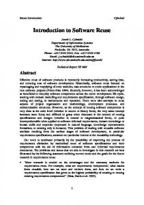
Lesson 1: Rely on an abstract and stable description of the problem to solve. Most product lines approaches involve a top down approach, in which an initial analysis phase identifies the commonalities and differences among family members. This analysis is used to build a common architecture with a number of variation points (places in the architecture reflecting the expected variations among products) to deal with diversity. The goal of this architecture is precisely to identify the common functionalities, their relationships and where differences (variations) are expected among the family members. This leads to an abstract architecture in terms of large functionality sets and variations, not in terms of technical components. This architecture describes the product, from its functionality point of view (the problem to solve), rather than the technique to use (the solution point of view). This architecture is somehow independent from technology changes; it is stable and for that reason, it is the cornerstone of the family. Indeed, it is the prime reusable artifact. We conclude that this is a required characteristic for high-level reuse. Lesson 2: Identify explicitly the variations in terms of features, not in terms of a solution. Variation points are indicated with respect to the abstract architecture and are therefore themselves expressed in terms of abstract functionalities, often called “features,” rather than in terms of technology. Consequently, they share the property of being rather stable. It is the presence of variation points that allows the architecture to be shared by a large number of products (the family). Lesson 3: Reuse coarse-grain, high-functionality components. The architecture identifies large common functionality sets, which become the reusable components. These components are relatively large and exhibit high-level functionalities. We believe this is an essential characteristic to avoid writing too much specific code and therefore to satisfy reuse criteria. Perhaps the strongest characteristic of product lines is the reliance on upfront analysis of commonality and variation, and on the assumption that it is stable enough and components are specified and specifically developed in-house within the closed context of the product family. Product line practitioners [2][10] have already shown that the approach fails to broaden the scope of the components beyond the product family, for instance toward an entire application domain (see the following figure from [1]). Family domain
Single Product
Application Domain
Population domain
Everything
Figure 1 The Spectrum of Product Scope, (from[1])
2.2
Reuse scope requirements
As they try to broaden the reach of the approach, the product line community has already identified many limitations and proposed appropriate enhancements. From their insight and from our own experience, we have identified requirements that must be satisfied for the product line family to reach the larger scope of reuse. Product lines rely strongly on the fact that the architecture and its variation points are stable. Adding new variation points, as well as changing the architecture have dramatic consequences; most often it leads to the definition of a new family. Requirement 1: Allow abstract architecture evolution. Since the scope of reuse is related to the capability of the variation mechanism to describe a large family, we conclude that variation mechanisms must be improved. Requirement 2: Variation mechanisms must be improved.
The code implementing a feature is usually scattered across multiple modules and the product line community adopted many aspect-oriented implementation techniques in order to handle this crosscutting feature interaction problem. In general, there is no direct relationship between a feature, described in abstract terms, and the underlying implementation. As identified in [13], a limitation of current product line mechanisms, hindering its applicability, is the complexity of the mapping between the high-level architectural view and the component implementation view. Requirement 3: A high level mapping between the abstract architecture and the components. So far, product line approaches reuse only the components specifically developed for the targeted product line. It means that a product line can only start from scratch; it is not possible to build a product line from an existing initial member. Increasing reuse scope requires reusing components developed elsewhere, for any other purpose, including other product lines, legacy and commercial components. It has been argued [1][10], that as one moves away from the product line family scope, a balance between the architectural (top-down) and the compositional (bottom-up) approaches is necessary; but a bottom-up approach requires reusing existing components developed elsewhere. Requirement 4: Reuse components developed elsewhere. In this paper we build from others' insight and from our previous work in coarse-grained component architectures [19], to propose software federations as an approach for the development of largescale domain components, combining the benefits of the product line architectural view, with a rich compositional approach able to achieve both large scale and large ratios of reuse.
3. SUPPORTED PRODUCT LINE APPROACHES
We believe that following the three lessons above is key to ensure a successful product line, which means a good reuse rate, but narrow reuse scope. We have identified that large scope of reuse could be satisfied if our four requirements above are satisfied.
Our hypothesis is that, if an automated support satisfies simultaneously the 3 product line lessons and our 4 requirements, both large rate and wide scope reuse can be achieved. We believe it would also significantly improve the scope of usability of product line approaches, and therefore its economic justification. The following is a short characterization of the classes of environments providing automated support for product lines, and an assessment on how they satisfy, or not, the lessons and requirements.
Meta Model (Abstract architecture) Conform to Model (Actual Architecture)
We present here shortly the most salient supported product line approaches: Domain Specific Language (DSL), Generative Programming (GP), Model Driven Engineering (MDE) and Domain Specific Modeling (DSM).
3.1
Conformance Checking
In product line approaches, the actual architecture of one family member must conform with the common abstract architecture. A way to make the conformance formal and verifiable, is to consider that the formal architecture is a language and the actual architecture is a “program” written in that language (Figure 2). If so, a compiler can check that the program conforms, both syntactically and semantically, and can translate it to executable code.The abstract architecture can therefore be formalized as a Domain Specific Language (DSL). The advantages of a DSL over a general purpose language are:
•
high-level, domain-specific concepts are promoted as first class entities,
•
a syntax (graphical or not) natural to the user in the domain, who are not necessarily “programmers,”
•
much domain knowledge can be embedded in the compiler to generate efficient executable code, and
•
the compiler can rely on high-level specific libraries that embed much domain expertise.
The main drawback of a DSL is that it covers only a limited scope, i.e. what can be said in the language. This is not a serious problem, as long as the language covers the whole family spectrum. Regarding the product line lessons, the DSL approach fares as follows: Lesson 1: Rely on an abstract and stable description of the problem to solve. This lesson is satisfied since the abstract architecture (the language) is stable and describes the problem space.
Problem Space Specific member Abstractions
Compiler / Mapping
Specific member Implementation Abstr.
Mapping Domain Library
Domain Specific Language (DSL)
A DSL is a textual or graphical language providing first class abstractions that directly represent the concepts of the application domain. A DSL is intended to be “simple” and natural to use by domain professionals, but covering a limited application scope. DSLs usually rely on classic programming language technology. We discuss first why DSLs are a good approach to support product lines.
Common domain Abstractions
Domain Componnents
Solution Space Common impl. Abstractions Common Implementation
Figure 2 The DSL Approach Lesson 2: Identify explicitly the variations in terms of features, not in terms of a solution. This lesson is not satisfied, since DSLs do not focus on variability in the problem space, but rather on variability in the solution space. Their goal is mainly to support transparent evolution in the solution space. Lesson 3: Reuse coarse-grain, high-functionality components. This lesson is satisfied, but only for specifically developed components. With respect to our requirements, DSLs fare as follows: R1: Allow abstract architecture evolution. The language is static and is not supposed to change. R2: Variation mechanisms must be improved. DSLs do not natively include variation facilities at the problem level. R3: A high-level mapping between the abstract architecture and the components. The compiler manages the mapping between architecture and components, but this is hidden in the compiler code. R4: Reuse components developed elsewhere. No, DSLs typically support a top-down approach only. DSL
3.2
L1 ***
L2
L3 ***
R1
R2
R3
Generative Programming (GP)
R4
Generative programming is a system family approach, which focuses on automating the creation of system family members; a given system can be automatically generated from a specification written in one or more textual or graphical DSLs. To reach this objective, GSD uses DSL in a very specific way : the language is directly designed after the feature model. GP strongly emphasizes variation control; the first step is feature model identification, through domain analysis. It hypothesizes variations will be very stable all along the product line life. The DSL mostly serves as a high-level way to select the features, in conformance with the model feature semantics and constraints. The architecture must be designed in such a way that different feature combinations can be implemented easily; it is a solution perspective. There is not really a problem perspective in GP, only a feature perspective in which different concerns, at different levels of abstraction are intertwined (Figure 3).
Stakeholders and other information sources Domain analysis
Solution-space perspective
Feature models Problem-space perspective
Architecture and components
DSL
Figure 3 Feature Oriented approach, from [35] Regarding the product line lessons, the GP approach fares as follows: Lesson 1: Rely on an abstract and stable description of the problem to solve. This lesson is not satisfied, since the architecture is fully in the solution space, but the DSL can play that role and is supposed to be in the problem space. Lesson 2: Identify explicitly the variations in terms of features, not in terms of a solution. This lesson is partially satisfied since many features logically pertain to the solution space. Lesson 3: Reuse coarse-grain, high-functionality components. This lesson is satisfied only for the specifically developed components. With respect to our requirements, the GP approach fares as follows: R1: Allow abstract architecture evolution. The feature model is very static. No evolution is possible. R2: Variation mechanisms must be improved. The variation mechanism is powerful (feature model), but it does not differentiate between variations in the problem space and variations in the solution space. R3: A high-level mapping between the abstract architecture and the components. The DSL compiler is in charge of this mapping, it is fully hidden in the compiler implementation. R4: Reuse components developed elsewhere. No, GP is typically a top-down approach. GP
3.3
L1 *
L2 **
L3 ***
R1
R2 **
R3
R4
Model Driven Engineering (MDE)
Fostered by the OMG Model Driven Approach (MDA) proposal in 2000 [36], recent approaches, under the general name Model Driven Engineering (MDE), are trying to leverage a model approach. A recent line of work intends to adapt MDE approaches to product lines. We discuss first the basic concepts underlying MDE. In the MDE community, a model is defined as a simplification of a system built with an intended goal in mind. The model should be able to answer questions in place of the actual system [25]. MDE is characterized by the fact that models conform to explicit and formal meta-models. A meta-model is a model that defines the language for expressing a model ([23], [30], MOF 2002). From that point of view, MDE, DSLs and programming languages share many concerns and techniques. The MDA approach (proposed by the OMG) was the first MDE proposal [36]. MDA is relies on an unique, universal, widescope language: UML and its profiles. The recent trend in MDE is
to consider instead many specialized meta-models intended to describe partial views of a system and only in a well defined and limited area of concern. The modern MDE approach is pretty close to a DSL approach, but, in contrast with DSLs, MDE makes the hypothesis that the target system is described by many different models, each one describing a different view, and/or a different level of abstraction. MDE relies on explicit and formal (executable) composition and transformation models, to obtain new models and, gradually, an executable system out of the many source models. For that reason MDE heavily relies on formal meta-models, from which the different tools (model editors, transformation, composition languages and so on) can be generated. MDE is primarily concerned in capitalizing on domain knowledge through specific meta-models (expressing the relevant domain concepts) and transformations (expressing expertise in the translation between concepts and their implementation for a specific platform). But MDE is (currently) a top-down approach, not primarily concerned with variability and product line issues. Regarding the product line lessons, the MDE approach fares as follows: Lesson 1: Rely on an abstract and stable description of the problem to solve. Yes. It is what models and meta-models are intended to do. Lesson 2: Identify explicitly the variations in terms of features, not in terms of a solution. No, variations can only be addressed if alternatives are part of the meta-model. Lesson 3: Reuse coarse-grain, high-functionality components. This lesson is partially satisfied since it is a generative approach, but it is not easy to reuse high-level components. With respect to our requirements, the MDE approach fares as follows: R1: Allow abstract architecture evolution. No, meta-models are very static. R2: Variation mechanisms must be improved. No, there is no variation mechanism at all. R3: A high-level mapping between the abstract architecture and the components. Yes, it is what transformations are intended to do, but transformation technology is not really available today. R4: Reuse components developed elsewhere. No, MDE is a top-down approach, reuse of external component is very limited. MDE
3.4
L1 ***
L2 *
L3 *
R1
R2
R3 (***)
Domain Specific Modeling (DSM)
R4
The DSM approach looks similar to a generative approach, it relies on three elements: a DSL, a generator and a framework. As for generative programming, a domain analysis is performed first with a model as output (see Figure 3), but in contrast with GP, this model is a description of the domain concepts and behavior, not a variation model. As in GP, this model serves as input for the definition of the DSL: the domain model is also the application meta-model. The DSL is a language in which the domain concepts and some of its high-level variations can be expressed. As such, de facto, all applications defined with this DSL satisfy the domain constraints and make some variations explicit. DSM recognizes that there exists different kinds of variations and that they should be handled differently. The high-level variations, i.e., those directly affecting the concepts, should be part of the DSL. They are visible to anyone designing a family member and decisions are made in the model itself. Those related to target variations should be part of the generator. They are managed by those in charge of the generation. A third class of variations are
directly pushed down into the framework; they are defined and implemented by the expert of each platform. DSM gets closer to our requirements, in particular by having a better domain model and a better feature model; nevertheless it follows the general DSL strategy as exemplified in Figure 2 and as such has the same drawbacks. Regarding the product line lessons, the DSM approach fares as follows: Lesson 1: Rely on an abstract and stable description of the problem to solve. Yes, this is the direct advantages of the MDE approach. Lesson 2: Identify explicitly the variations in terms of features, not in terms of a solution. Yes, three levels of variations are independently handled. Lesson 3: Reuse coarse-grain, high-functionality components. Yes, for components specifically defined for that domain. With respect to our requirements, the MDE approach fares as follows: R1: Allow abstract architecture evolution. No, meta-models are very static. R2: Variation mechanisms must be improved. Yes, the three levels of variation is a clear improvement. R3: A high-level mapping between the abstract architecture and the components. Yes, if explicit transformations are use, but it is not the case; in current DSM tools, classic code generation is used instead. R4: Reuse components developed elsewhere. No, DSM is a top-down approach, reuse of external component is very limited. The following summarizes the strengths and weaknesses of the various approaches.
evolve under unplanned external constraints and so on. Reusing externally developed components and avoiding the big bang syndrome means it must be possible to add/remove/change components, at any time, either for the whole family or for a single family member. This context defeats the implicit hypothesis made in MDE, that transformations are performed for a target meta-model that is stable and well known before hand. For example, in Figure 2, the transformation consists of generating code for the domain library, seen as the target meta-model. It is not economically feasible to build a transformation tool or compiler for an unstable meta-model (domain library). In this case, the only stable meta-model is the domain model. An application model is a “program” in the language defined by the domain model. Interpretation is often defined as an execution in terms of the language concepts themselves, i.e., an execution on top of a virtual machine that is the domain model. To be able to interpret the application model, we have to perform two transformations: 1. transforming the domain model into an interpreter, 2. transforming the application models into a program interpretable by that interpreter. Domain Model (Appli. Meta Model) Transformed to Conform to Application Model (Actual Architecture)
Interpreter
Abstract execution
DSL GP MDE DSM
4.
L1 *** * *** ***
L2 ** * ***
L3 *** *** * ***
R1
R2 ** **
R3
R4
•
•
Model mapping
Mapping
THE MÉLUSINE APPROACH
Current approaches require starting a product line from scratch, there is no way to define a product line from an existing application. The product line approach is too much of a big bang approach.
The economic viability of the approach is based on how often a component is reused. Extending the scope means improving the opportunities to reuse a component. As shown in 2.2 four requirements must be satisfied to reach the objective; clearly no current approach can satisfy these requirements. We have found that requirement 4 (reuse existing components developed elsewhere), is probably the most critical one for improving reuse scope.
4.1 R4: Reusing existing components: Abstract execution vs. compilation
Our goal is to reuse components developed elsewhere as much as possible. These components are not made for our product line purposes; they can be different in many respects. These components can use different technologies, different platforms, propose different kinds of interfaces,; they can be interactive, run on different computers, have overlapping functionalities; they
Specific member Abstractions
AOP Machine
(***)
Mélusine is a system family approach based on MDE technology, which emphasizes improvements on product line approaches through the extension of the scope of reuse. Motivations are twofold:
Common domain Abstractions Problem Space
Roles Tools
Solution Space Implementation Abstractions Common Implementation
Figure 4 Model interpretation and mappings In Mélusine we are using a rather simple approach: the first transformation consists in reifying the meta-model, i.e., transforming each domain concept into a (Java) class and its operations into methods of that class. The second transformation reifies the application models in terms of instances of these classes, directly interpreted by the interpreter. Note that other transformations leading to model interpretation are possible; we use reification because it is natural and directly supported by most UML environments. If the meta-model is itself defined in a formal language (e.g., ENBF, MOF or UML), many tools can be generated. It is the case for model editors and also for our transformations (Meta model -> interpreter; Model -> program) that tool generation can be highly automated. Mostly, the code of the meta-model operations (the interpreter methods) need to be defined. Such an interpreter is pretty easy to write, nothing comparable with a DSL compiler. The model interpretation remains in the problem space; we have a symbolic execution of the family member, in problem terms; it is easier to check and change the application to fit the requirements (Figure 4).
1.
4.2 R3: High-level mapping vs. code generation
This approach satisfies R4: it is now possible to reuse components defined elsewhere. Conversely, we are no longer generating code for the domain library; the mapping has to be done in other ways. Classes found in the interpreter represent domain concepts. The methods in these classes interpret the objects in terms of the solution space. For example, if “product” is a product line concept, its “getProduct(…)” method returns a Java object with the attributes defined in the domain model. In the solution space, the corresponding real data is usually not a Java object, it may be the clustering of information coming from different sources, in different tools. There is not necessarily a direct mapping between a concept and an implementation of the concept. Since we require the domain model to be independent from the implementation, it is not possible to change the interpreter to include the mapping. We rely instead on aspect-oriented technology [14][15]. When a method of the interpreter is called (say “getData(..)” ), the associated implementation captures that call and translates it into a number of calls on the actual components and fills the Java object attribute values accordingly. More than one implementation can be associated with a single domain model: they express variations in the way the domain can be implemented. It is our second degree of variation. When compared with traditional compiler technology, the compiler is split into three parts: the interpreter (in the problem space), the interfaces and tools (in the solution space), and the mapping.
R3: A high-level mapping between the abstract architecture and the components is supported since:
The abstract architecture (the application model) does not disappear, it is translated into an executable program at the same abstraction level.
The rest of the mapping is explicitly defined in term of an association between a concept (a class in the interpreter) and the interfaces of the tools. Since the mapping relies on roles, not on tools, this approach enables using different tools, without having to change the mapping. This variability proves to be extremely valuable. It allows an interface to have different implementations either to fit the non-functional characteristics required by a specific family member (size, speed, processors, and so on), or to satisfy some client requirement, for example, (re)using the data base, version manager and tools used by the client. It is the selection of the “right” tool to play the role that will provide specific characteristics to the role. Tool versions and alternative tools provide a third degree of variability. As with DSM, variability is handled at the three abstraction levels, for three different reasons, and by three different kinds of persons: •
high-level variations are part of the domain model and defined by each family member designer.
•
Non-functional concept variations are handled in the mapping layer by the configurator.
•
Platform and tool variations are performed by platform and tool experts.
As for DSM, most of the R2 requirement: improve variability mechanism is satisfied. Only R1 is missing: improve abstract domain variability.
4.3
R1: Abstract Domain variability
Abstract domain variability is supported by two mechanisms : features and extensions.
UML
Feature Meta Model
Domain Model (Appli. Meta Model)
Feature Model F1F2,F3 F1, F3, F2 … Fn
Conform to
Conform to
Conform to
Transformed
Application Model
Model Interp.
Transformed
Feat. Interp.
Conform to
Feature Selection
Domain indep. Description lg. Common domain Abstractions & Common Features
Problem Space Specific F. member Abstractions & features
AOP Machine Model Mapping
MF1
MF2 MF3
Model Mapping & Feature Mappings
Solution Space Tool Abstractions Tools & component Implementation
Domain modeling
Feature Modeling
Figure 5 Feature and Domain modeling
4.3.1
Feature Management.
The domain model includes those variations that affect the conceptual domain and the mapping variation on the implementation of a given concept, but other variations are related to behavioral variation or to non-functional properties, not related to a single concept. For that reason, in Mélusine, the domain model is complemented by a feature model, which captures optional domain behavior. In traditional product line approaches, features are part of the abstract architecture (or DSL), they are statically defined a priori. In Mélusine, features are not part of the domain model, therefore, they can be identified a posteriori, incorporated into the system at any time, and maintained independently. Nevertheless, features are not independent from the domain model; they provide extended or additional semantics for the
concepts present in the domain model. Features can be considered as crosscutting concerns regarding the interpreter; for this reason, we use aspect-oriented techniques to implement features and articulate them with the domain concepts, along with the ideas of feature refinements described in [12]. variability with respect to the domain model. Configurable domains can be adapted to different contexts simply by selecting among the available features, in a similar way as configurable product families [11]. Since the conceptual domain and the features are high level, the configuration model is simple and the environment can perform a number of validations. It is interesting to see that this approach merges the generative programming (feature modeling) and DSM (domain modeling) approaches, getting the best of both (Figure 5).
Domain indep. Description lg.
UML Domain Ext. 2
Core Domain Domain Model Ext. 1 Extended Domain Model Transformed
Transformed
Core Ext.2 Ext. 2 Application Application Interpreter Model Model
Transformed
Ext1 Core Ext. 1 Interpreter ApplicationInterpreter. Model
Common domain Abstractions
Domain Problem Space Specific F. member Abstractions
AOP Machine Extention 2 Mapping
Extention 1 Mapping
Core Model Mapping
Core Mapping & Extention Mappings
Solution Space Tools Abstractions Tools Implementation
Ext1 Domain
Core Domain
Ext2. Domain
Figure 6 Domain model extensions
4.3.2
Domain extensions
Features provide a level of variability in the domain model, nevertheless, during the product line life span, it is likely some new concepts appear, or therefore that the domain model itself will need to be extended. This usually has dramatic consequences since the generator and mapping need to be redone, and future family members will not conform with the previous architecture: it is more appropriate to say that we will have a new product line. The challenge is to be able to extend the domain model without any impact on the current domain model, called the core domain model. To do so, we have designed an original model composition approach in which a new set of concepts, called a model extension, can be defined. These concepts can relate to each other using the usual UML relationships, and can also refer to the core concepts (some of their attribute can be references to the core concepts), but not the other way around: core concepts do not refer to the extended concepts. The consequence is that core domain concepts, its (core) interpreter, the mapping and the application models are totally unchanged.Each domain extension is transformed, in the same way as the core domain model, in an interpreter and mappings, for the same or different tools. Each
domain extension interprets a specific model, in which the specific application use of the extended concepts is defined (Figure 6). An extended model can refer to the core model. The approach has three major benefits: 1. Extensions are independent: they depend on the core domain only, not on other extensions. 2. Each family member uses the core domain model and zero or more extensions. 3. New extensions can be defined at any time in the product line life cycle. This technology consists of composing the domains models (composition common to each family member) and composing application models (composition specific to each family member). Features and extensions provide domain model variability (R1), without compromising the stability property of the domain model which is central to product line approaches (Lesson 1).
5.
SUMMARY
Mélusine is a system family approach, which focuses on reusing existing heterogeneous components and extending the scope and rate of reuse, based on an MDE approach.
From one side, in Mélusine, the problem space is explicitly modeled (it is the domain model), this model contains the most relevant domain concepts, in which some variations can be exposed (for example, in UML, a choice can be modeled as 2 subclasses of the same concept). Mandatory choices are part of the domain meta model and, therefore, are expressed in the family member model. Mélusine extends MDE with a feature meta-model in exactly the same way as in GSD. In Mélusine, features are optional properties that can be present or not (turned on/off) for each family member. Conceptual extension of the domain model is attained by domain extensions. Extensions can be defined at any point in time and be use or not by sub-family members. Features and extensions allow for abstract architecture evolution and variation. The family member core model, extension models and feature model are part of the problem space; it contrasts sharply with the very static abstract architecture found in traditional product line approaches. The solution space is independent from the problem space. Mélusine proposes a high-level mapping between the problem and solution spaces, based on an AOP technology. This language, another DSL, allows it to handle variability in the solution space. We claim Mélusine satisfies both the lessons and our requirements. Lesson 1: Rely on an abstract and stable description of the problem to solve. Yes, this is the direct advantages of an MDE approach. Lesson 2: Identify explicitly the variations in terms of features, not in terms of a solution. Yes, the three variation mechanisms: domain model, features model and extensions models are provided at the problem layer. Two other variation layers are also available (mapping and tools). Lesson 3: Reuse coarse-grain, high-functionality components. Yes. R1: Allow abstract architecture evolution. The feature mechanism, for optional behavior, and domain extension for conceptual extension allow for the extension of the domain model, without compromising the stability of the core model. R2: Variation mechanisms must be improved. Yes, 5 different variation mechanisms, on three levels of abstraction are independently handled. R3: A high-level mapping between the abstract architecture and the components. Yes, the mapping and the technology allows one to define, at a high level, the mapping between concepts and roles. However, a formal transformation approach, in the line of QVT would provide better results, but it is not currently available. R4: Reuse components developed elsewhere. This was the primary goal of Mélusine. It relies on (1) making the application model interpreter independent from implementation (abstract execution); (2) making explicit the mapping between concept and roles, and (3) defining an independent a mapping between roles and the actual tools and components. L1 ***
L2 ***
L3 ***
R1 ***
R2 ***
R3 **
R4 ***
We believe our goal, following the three product line lessons and satisfying our 5 requirements have been reached; accumulated experience along the 5 last years tend to show our hypothesis is verified in practice: we have both a pretty good product line supported approach with both a good reuse rate and good reuse scope.
6. EXPERIMENTATION AND VALIDATION
Many of our claims have been substantiated by our experience in developing several production systems using Mélusine; see [20] for details. Most of our work concentrated on the area of Process Support Systems. This is a challenging area since its original usage in Workflow systems has been extended to encompass systems as diverse as Business Process Management, Enterprise Application Integration solutions, or Web Service orchestration and choreography. This diversity can also be exemplified by the variety of the systems we have developed: document management for a transport company, process support for the development of memories in the ST microelectronics company, a process-driven system for largescale software deployment, or tool integration to support the development of software reusable components. Even our own Mélusine design and development environment has been designed and developed as a Mélusine application. Perhaps the most difficult task is to identify the core domain model because it really requires domain expertise. In contrast to other product line approaches, our extension mechanism pushes designers toward very simple core domains, because they know it will always be possible to add concepts and features later on. We observed it had a dramatic effect on the size and complexity of the core models. For example, we redesigned our workflow product line Apel V4, and observed a 10 fold reduction of the core model size; three years later, the first extension was designed (an exception and error recovery extension). We have developed different independent product lines for independent customers and we observed a very good reuse of components across these product lines, most notably process management, product management, document management, workspace management, resource management and concurrent engineering domains. A project management and a configuration management product line are under construction. We observed that, once the domain model is defined, adding new features is easy and powerful, adding extensions is a bit more difficult, but still relatively easy.
7.
CONCLUSION
The solution we propose can be seen as a generalization and extension of the product line approach. Indeed we reused (sic) the main ideas coming from product lines. The idea to rely on a high-level abstract architecture (lesson 1) has been extended to handle the populations scope instead of a family; using a model / meta-model approach borrowed from the MDA/MDE world. Features are also defined in terms of the abstract architecture (lesson 2); but are not part of the architecture, they can be defined at any time. A third level of variability is achieved by conceptual extensions. These three variability mechanisms at the problem layer solve both the abstract architecture (R1) and the variability extension (R2) issues. We support the idea that high reuse rate can be achieved only if it is possible to reuse coarse-grain components (lesson 3). But we also believe the real challenge is to reuse coarse grain components developed elsewhere, for other purposes (R4). Solving this issue required reworking many aspects of the system. We had to use abstract interpretation instead of compilation, to define high-level mappings (R3) and to carefully manage tools abstractions and variations. Extending the scope of reuse is the main challenge addressed in this work. Reaching this target required many deep changes. The
first one is to completely separate the problem layer from the implementation layer. The problem layer contains:
•
a core domain model: a stable set of core concepts,
• •
a feature model: core model optional behavior, domain extensions: core model additional concepts. The problem layer is transformed into an executable program, and executed symbolically. The problem layer is also divided in three parts:
• • •
A mapping between the problem and implementation layers. Roles, defining abstract components functionalities, Tools : software component capable to fill a role.
We believe this work contribute is different ways: We clearly separate the problem layer from implementation. At the problem
REFERENCES
[1] R. van Ommering. Roadmapping a Product Population Architecture. In proceedings of the 4th International Workshop on Product Family Engineering (PFE 4), October 2001. [2] R. van Ommering. Mechanisms for handling diversity in a Product Population. In proceedings of the 4th International Software Architecture Workshop (ISAW 4), June 2000. [3] E. Evans. Domain Driven Design: tackling complexity in the heart of software. Addison-Wesley, 2003 [4] J. McGregor. “Domain *”. In Journal of Object Technology, Vol. 3, No. 7, July-August 2004 [5] S. Henninger. “Supporting the Domain Lifecycle”. In proceedings of the 7th Workshop on Computer Aided Software Engineering (CASE 95), July 1995. [6] S. Mellor, M. Balcer. Executable UML: A Foundation for Model Driven Architecture. Addison-Wesley, 2002 [7] S. Mellor, K. Scott, A. Uhl, D. Weise. MDA Distilled: Principles of Model-driven Architecture, Addison-Wesley, 2004 [8] P. Clements, L. Northrop. Software product lines: Practices and Patterns. Addison-Wesley, 2001 [9] J. Bosch. Design and use of Software Architectures, adopting and evolving a product-line approach. Addison-Wesley, 2000 [10] R. van Ommering, J. Bosch. Widening the scope of Software product lines – From Variation to Composition. In Proceedings of the 2nd Software product line Conference (SPLC2), August 2002.
layer, we provide three different variation mechanisms and two extensions mechanism. A significant contribution is our technology for meta model and model composition. The mapping language we have developed links problem with implementation. We believe our system is one of the few PL approach supporting bottom up approaches. The approach have been significantly tested in real size operational applications. In order to reach high reuse rates, the product family approaches had to rework the usual software engineering concepts and techniques, and to propose specific development processes and environments. But in PL, reuse is limited to a narrow family scope. It is not a surprise that, to obtain high reuse rate in a much wider scope, we had to rework even deeper concepts, techniques and processes, and to develop a completely new environment. Technology. In Proceedings of the 8th International Conference on Software Reuse (ICSR 2004), July 2004 [15] J. Hallstrom, N Sridhar, P. Silvilotti, A. Arora, W. Leal. A container-based Approach to Object-Oriented product lines. In Proceedings of the 44th Technology of Object-Oriented Languages and Systems Conference (TOOLS USA 2003), September 2003. [16] D. Batory, R.E. Lopez-Herrejon, J.P. Martin. Generating Product-lines of Product-Families. In Proceedings of the 17th International Conference on Automated Software Engineering (ASE’02), September 2002 [17] D. Fey, R. Fajita, A. Boros. Feature Modeling: A Meta-Model to enhance Usability and Usefulness. In Proceedings of the 2nd Software product line Conference (SPLC2), August 2002. [18] H. Gomaa, M. Shin A Multiple-View Meta-modeling Approach for Variability Management in Software product lines. In Proceedings of the 8th International Conference on Software Reuse (ICSR 2004), July 2004 [19] T. Le-Anh, J. Villalobos, J. Estublier. Multi-level Composition for Software Federations. In Proceedings of the 6th European Joint Conferences on Theory and Practice of Software (ETAPS 2003) Workshop on Software Composition, April 2003 [20] J. Estublier, J. Villalobos, T. Le-Ahn, S. Sanlaville, G. Vega. An Approach and Framework for Extensible Process Support System. In Proceedings of the 9th European Workshop on Software Process Technology (EWSPT 2003), September 2003 [21] Atkinson C., Kühne T., "Model-Driven Development: A Metamodeling Foundation", IEEE Software, September 2003
[11] S. Deelstra, M. Sinnema, J. van Gurp, J. Bosch. Model Driven Architecture as Approach to Manage Variability in Software Product Families. In MDAFA 2003, CTIT Technical Report TR-CTIT-03-27, June 2003.
[22] Bézivin, J. In search of a Basic Principle for Model Driven Engineering, Novatica/Upgrade, Vol. V, N°2, (April 2004), pp. 21-24, http://www.upgradecepis.org/issues/2004/2/upgrade-vol-V-2.html
[12] D. Batory, J.N. Sarvela, A. Rauschmayer. Scaling step-wise Refinement. In Proceedings of the 25th International Conference on Software Engineering (ICSE 2003), May 2003
[23] OMG, "Meta Object Facility (MOF) Specification" Version 1.4, April 2002
[13] M. Griss. Implementing Product-line Features by Composing Component Aspects. In Proceedings of the 1st Software product line Conference, August 2000 [14] M. Anastasopoulos, D. Muthig. An Evaluation of AspectOriented Programming as a product line Implementation
[24] Bézivin, J., Gérard, S. Muller, P.A., Rioux, L. MDA Components: Challenges and Opportunities, Metamodelling for MDA, First International Workshop, York, UK, (November 2003), http://www.cs.york.ac.uk/metamodel4mda/onlineProceedings Final.pdf
[25] Bézivin, J., Gerbé O., "Towards a Precise Definition of the OMG/MDA Framework", ASE'01, Novembre 2001 [26] Booch G., Brown A., Iyengar S., Rumbaugh J., Selic B. The IBM MDA Manifesto The MDA Journal, May 2004, http://www.bptrends.com [27] Favre J.M., "Towards a Basic Theory to Model Model Driven Engineering", 3rd Workshop in Software Model Engineering, WiSME 2004, http://www-adele.imag.fr/~jmfavre [28] Greenfield, J. & Short, K. "Moving to Software factories", Software development, http://www.sdmagazine.com, Juillet 2004. [29] Groupe OFTA Ingénierie de Modèles logiciels et Systèmes, Arago #30 [30] Kleppe, S. Warmer, W. Bast, "MDA Explained. The Model Driven Architecture: Practice and Promise", Addison-Wesley, April 2003
[31] Kurtev I., Bezivin J. , and Aksit M.. "Technological spaces: an initial appraisal.", In CoopIS, DOA'2002 Federated Conferences, Industrial track, Irvine, 2002 [32] Mellor S.J., Scott K., Uhl A., Weise D., "MDA Distilled: Principles of Model-Driven Architecture", Addison Wesley, March 2004 [33] OMG The MOF/QVT Queries, Views, Transformations request for proposal Soley, R. & the OMG staff MDA, Model-Driven Architecture, November 20000, http://www.omg.org/mda/presentations.htm [34] Seidwitz E., "What Models Mean", IEEE Software, September 2003 [35] Czarnecki K. Overview of Generative Software Development
[36] Soley, R. and the OMG staff. “Model-Driven Architecture”. White paper, Draft 3.2. Available at www.omg.org, November 2000.