Ãrea Departamental de Engenharia 7800-050 Beja, Portugal, [email protected]. 2 Universidade Nova de Lisboa, Faculdade de Ciências e Tecnologia, ...
Class diagrams are the richest notation in UML. Class diagrams ..... r Example:
Somebody in a hospital may be a patient, a doctor, a nurse or simply a person.
Subject/Topic/Focus: r Class Diagrams: Modeling Static Structure. Summary: r
Perspectives: ... Class diagrams are the richest notation in UML. Class diagrams
...
Software maintainers need tools to recover class diagrams from programs source code and binaries, which are the only sources of data available usually during ...
other classes) from method invocations, which are collected during the execution ... asked to repair a fault in the 'Save' feature of a word pro- cessing application. .... The auto-programming system was the basis for an algo- rithm developed by ...
asked to repair a fault in the 'Save' feature of a word pro- cessing application. ... ios for the File class. Software ..... self-calls (i.e., invocations an object made to itself) from the .... Working Conference on Reverse Engineering (WCRE), Vic-.
There was a problem previewing this document. Retrying... Download. Connect more apps... Try one of the apps below to op
There was a problem previewing this document. Retrying... Download. Connect more apps... Try one of the apps below to op
Jun 22, 2016 - 2007-2012, LoT received funding from the Provost to hire full-time staff .... http://celt.uwindsor.ca/ojs/leddy/index.php/CELT/article/vi ew/4283.
UML Class Diagrams (UCDs) are the best known class-based formalism for conceptual .... fore, in this section, we recall some basics on relational instances, (Boolean) con- junctive queries ...... 5 http://dl.dropbox.com/u/3185659/uml.pdf ...
University: solution. Diagram made with Omondo UML tool. Movie- Shop. ▫
Design a system for a movie-shop, in order to handle ordering of movies and ...
Class Diagram. Exercises. Politecnico ... Diagram made with Omondo UML tool.
Politecnico di ... People working in a hospital have an ID , unique in the hospital ...
University of California, San Diego. La Jolla, CA 92093-0114, USA. CSE 70:
Unified Modeling Language – Class Diagrams. Design Patterns – Strategy.
Email: [email protected]. Keywords: ... their business knowledge into software design and ... in software development paradigm from the Business Modelling.
proach based graph transformation and registered in the MDA architecture for .... model transformation, written in Python [8] and is carried out on various ...
Currently, Learning Objects (LOs) [2] are leading as a technology of choice for ... a specific Learning Management System (LMS) [5], or to describe the content ...
Construx Software. Object Modeling with UML. Class Models (14-Jan-01). Page 4-1. Class Diagrams. ⢠Basic Concepts. â¢
2015. [10] Rumbaugh J, Booch G, Jacobson I. The unified modeling language user guide. ... language reference manual. Upper Saddle River (NJ): ..... For example, in Figure A14, we attached a note 'K.A. Opportunity: Insert sequence to ...
One of the noblest uses of epidemiology is the investigation of sources of inequalities in health outcomes. Research on prognostic factors of cancer survival ...
Practical UML: A hands on introduction for developers ... responsibilities:
problems to be solved; short verb phrases. ▫ ..... following systems? g y. ▫.
Nov 14, 1997 ... translate ER-schemas into UML class diagrams and vice versa. ...... Solution. ∗. 1
. Exercise. • With the standard (min,max)-notation this does.
Reverse Engineering Sequence Diagrams for. Enterprise JavaBeans with Business Method. Interceptors. Alexander Serebrenikâ, Serguei Roubtsovâ, Ella ...
Sep 26, 2013 - The fault injection attacks consist in disrupting the circuit behaviour. FIRE Fault Injection for Reverse Engineering. FIRE DES. Le Bouder. 09/26/ ...
Sep 26, 2013 - (R16 â R16â). Si(mi) â Si(mâi )=âyi. S-boxes are defined up to a translation. They finish with an exhaustive search. FIRE DES. Le Bouder.
design of the software and sequence diagrams to visu- alize the ... nology of Object-Oriented Languages and Systems (TOOLS. Pacific 2002) ... extensions to accomodate C++ language constructs ... dard, version 1.3, than the other tools. ..... terprise solutions. .... Modeling Language Reference Manual, Addison Wesley.
Reveal: A Tool to Reverse Engineer Class Diagrams Sarah Matzko, Peter J. Clarke, James F. Power and Rosemary Monahan Tanton H. Gibbs, Brian A. Malloy Department of Computer Science Computer Science Department National University of Ireland Clemson University Maynooth, Co. Kildare Clemson, SC 29634 Ireland {smatzko,peterc}@cs.clemson.edu
Abstract Many systems are constructed without the use of modeling and visualization artifacts, due to constraints imposed by deadlines or a shortage of manpower. Nevertheless, such systems might profit from the visualization provided by diagrams to facilitate maintenance of the constructed system. In this paper, we present a tool, Reveal, to reverse engineer a class diagram from the C + + source code representation of the software. In Reveal, we remain faithful to the UML standard definition of a class diagram wherever possible. However, to accommodate the vagaries of the C + + language, we offer some extensions to the standard notation to include representations for namespaces, stand-alone functions and friend functions. We compare our representation to three other tools that reverse-engineer class diagrams, for both compliance to the UML standard and for their ability to faithfully represent the software system under study. Keywords Reverse Engineering, Unified Modeling Language, UML, Class Diagram, Automated Construction, Object-Oriented Programming 1
Introduction
The deliverable produced by a quality development process is excellent software that satisfies the evolving needs of its users. One approach to the production of such software requires the construction of models to visualize and control the systems evolving architecture, requirements, structure and behavior. The Unified Modeling Language (UML) has rapidly become the language of choice for developers who wish to visualize and model the system under development. The UML includes use cases to facilitate visualization of user requirements, class diagrams to visualize the design of the software and sequence diagrams to visualize the behavior of the objects in the system. Unfortunately, many systems are constructed without the use of modeling and visualization artifacts, due to constraints imposed by deadlines, or a shortage of manpower. Nevertheless, such systems might profit from the visualization provided by the UML diagrams to facilitate maintenance of the constructed system. In this paper, we present c Copyright 2002, Australian Computer Society, Inc. This paper appeared at the 40th International Conference on Technology of Object-Oriented Languages and Systems (TOOLS Pacific 2002), Sydney, Australia. Conferences in Research and Practice in Information Technology, Vol. 10. James Noble and John Potter, Eds. Reproduction for academic, not-for profit purposes permitted provided this text is included.
a tool, Reveal, to reverse engineer a class diagram from the C + + source code representation of the software. In Reveal, we remain faithful to the UML standard definition of a class diagram wherever possible. However, to accommodate the vagaries of the C + + language, we offer some extensions to the standard notation to include representations for namespaces, stand-alone functions and friend functions. We compare our representation to three other tools that reverse-engineer class diagrams: Superwomble(Jackson & Waingold 2001), Rational c and TogetherSoftTM (TogetherSoft 2001). We Rose compare the tools for both compliance to the UML standard and for their ability to faithfully represent the software system under study. We have found Reveal to be useful for reverse engineering class diagrams of legacy code. However, Reveal does not provide round-trip engineering; that is, users cannot construct a class diagram, use the diagram as a guide to code development, and then reverse-engineer the resultant code back to a class diagram. Nevertheless, the contributions of our work are threefold. First, our tool is more precise than the three tools that we used in our comparison. We suspect that the other tools do not use a full parse to guide the reverse engineering process, but rather use a fuzzy parse that scans the code for keywords(Asveld 1995, Koppler 1997). In Reveal, we use keystone to provide a full parse of the code (Power & Malloy 2000, Power & Malloy 2001). A full parse permits reveal to capture class relationships that might be omitted in a fuzzy parse. Second, our extensions to accomodate C++ language constructs provide more complete modeling of the application. Third, our class diagrams are closer to the UML standard, version 1.3, than the other tools. In the next section, we provide background about class diagrams, graphviz, the tool that we use to draw the class diagrams, and about keystone the parser front-end that we use to parse the input program under study. In Section 3, we overview the Reveal system, including a discussion of its usage. In Section 4, we present our API, Clouseau, that permits inspection of the namespaces, classes, functions and variables in a C + + program. In Section 5, we describe construction of Reveal class diagrams and in Section 6, we compare Reveal to three other tools. Finally, we draw conclusions in Section 7. 2
Background
In this section, we provide background information about UML class diagrams, the graphviz tool, and the keystone parser front-end that we use to parse the
C + + input program(Power & Malloy 2000, Power & Malloy 2001). 2.1
UML Class Diagrams
Because of the complexity inherent in large programs, a developer, or group of developers, may not be able to grasp the overall design of the system, even if those involved are familiar with the source code. The Unified Model Language (UML) includes graph structures to represent aspects of the program, providing an overview of the programs structure and behavior(Booch, Rumbaugh & Jacobson 1999). The UML can help even non-programmers get a better grasp of the overall functionality of the system. A UML class diagram is a static representation of the program consisting of rectangles to represent classes in the system and lines connecting the rectangles to represent the relationships between the classes. In UML, a class is represented as a box with three vertical sections. The top section shows the name of the class. The middle section displays the variables belonging to the class, with symbols representing the visibility (public, protected, or private) and properties (constant or static). The bottom section contains the member functions of the class. Each method has a name, signature, and properties. There are four types of relationships in a class diagram: association, dependency, generalization and realization. Each relationship is represented in the diagram by a different type of arrow. An association is a structural relationship that describes a set of links, where a link is a connection among objects. An association can be a one-way or two-way relationship. Class A has an association with class B if class A has a data member of type B. If class B also has a data member of type A, then the relationship is bi-directional. A directed arrow to the associated class specifies a one-way relationship. A line (no arrowhead) signifies a bi-directional relationship. Associations are often adorned with numbers or symbols representing the multiplicity of the relationship, or how many objects of one class the other is using. Dependency is a semantic relationship between two classes in which a change to one class (the independent class) may affect the semantics of the other class (the dependent class). A method is said to use an object of a class if the object is passed in as a parameter, created in the method, or returned from a method. In UML, dependencies are designated by a dashed arrow from the dependent class to the class on which it depends. If both classes depend on the other, a double-headed dashed arrow is used. Dependency may also be used to show a special type of relationship between classes: friendship. If class A is a friend of class B, class A can access class B’s private information. Friend classes are denoted by a dependency arrow with the stereotype on the arrow. Generalization, or inheritance, is a specialization/generalization relationship where objects of the specialized element (the child) are substitutable for objects of the generalized element (the parent). Realization is a semantic relationship between classifiers, wherein one classifier specifies a contract that another classifier guarantees to carry out. In C++, an abstract base class, parent, has one or more purely virtual methods that every immediate child must overwrite. The contract between the parent and the child is that the child will overwrite these methods. Abstract classes are written in italics. Children of abstract classes are connected to the class by a dashed arrow with a hollow arrowhead.
2.2
The Graphviz Tool
Graphviz is a set of open-source drawing tools for creating directed or undirected graphs. Graphviz has two main purposes: creating graphs with good quality automated layout, and providing web drawing services that are easy to use. The layout of graphviz graphs is, in some cases, better than graphs drawn manually. Among the Graphviz tools, dot is best suited to drawing UML diagrams. dot constructs directed graphs laid out in a hierarchical fashion. In addition to its layout ability, dot also allows a great deal of variation, including different node shapes, various arrow types for connecting the nodes, and graphs inside graphs. dot’s layout algorithm places nodes in such a way that connecting lines seldom intersect and nodes appear organized. Part of dot’s algorithm for placement of nodes involves determining a node’s rank, or importance. When nodes are placed on a graph (with no arrows), dot will place them side-by-side, since these nodes all have the same rank. If an arrow is drawn between two nodes, the target will be moved down below the source of the arrow. The target now has a lower rank. In this manner, dot places each node. It is possible to specify that certain items must have equal rank. Dot provides for three possible output formats for the graphs it creates: graphics interchange format (GIF), portable network graphics format (PNG), or Postscript format. Reveal generates the UML diagram using dot and automatically displays the outputted Postscript. 2.3
Keystone
Keystone is a parser front-end for the ISO C + + programming language. Keystone uses a bottomup, bactracking parse algorithm, together with techniques such as token decoration to facilitate recognition of ambiguous language constructs. Figure 1 summarizes the design of keystone, our system to construct a parser front-end for ISO C++. The figure presents two subsystems, illustrated as tabbed folders and designated by the subsystem stereotype. The ProgramProcessor subsystem is shown on the left and the Symbol Table subsystem is shown on the right of Figure 1. The ProgramProcessor subsystem includes a Scanner and Parser and is responsible for initiating and directing symbol table construction and name lookup. This responsibility includes two phases: (1) assembling the necessary information for creation of a NameOccurrence object, and (2) directing the search for a corresponding NameDeclaration object in the Symbol Table subsystem. The NameOccurrence object encapsulates local information relevant to name lookup, including the String representation of the name, a boolean to indicate name qualification (by class or namespace), and an enumeration, OccurSpecifier, that captures lexical information about the context in which the name occurred. 3
Overview of the Reveal Tool
In this section, we overview the Reveal Tool. In Section 3.1, we describe the important subsystems used to build Reveal, including the Clouseau API that is an interface into the keystone parser front-end (Power & Malloy 2000, Power & Malloy 2001). In Section 3.2, we describe use of the Reveal tool, including our graphical user interface that permits users to set options to adjust the view of the class diagram.
Figure 1: Keystone. This figure summarizes the design of keystone, a parser front-end for ISO C++. The ProgramProcessor subsystem is responsible for initiating and directing symbol table construction and name lookup by marshaling information about the name in a NameOccurrence object and directing the search for a corresponding NameDeclaration in the Symbol Table subsystem.
3.2
input program Reveal Application Program
getInfo
returnInfo
Clouseau API
getInfo
returnInfo
Keystone Parser Front-end
UML Class Diagram
Figure 2: Reveal System Overview.
3.1
Overview of the Reveal System
Figure 2 illustrates the important subsystems in the Reveal tool. The box on the left of the figure is the Reveal program that contains the algorithm and data structures to construct a class diagram. The box on the right of the figure is the keystone parser frontend that we use to parse the input program, providing information such as type, scope and accessibility for variables, classes, and namespaces in the program. The box that is interposed between the Reveal program and keystone is an API, Clouseau, that allows the Reveal program to access keystone without having to understand keystone. Thus, the Reveal program never actually “sees” code, but rather retrieves any required information about the input program using Clouseau. The rounded box at the top of Figure 2, illustrates the C + + input code, input program, for which the Reveal system will construct a class diagram; the constructed class diagram is represented by the rounded box on the lower left of the figure, UML Class Diagram.
Using the Reveal Tool
Figure 3 illustrates a sample usage of the Reveal tool. The large rectangle on the left is the graphical user interface, GUI, that facilitates use of the tool, and the large rectangle on the right is an abbreviated version of a class diagram for the example program in Figure 4. Reveal permits users to choose many options including either a full class diagram that lists all data attributes and member functions for each class, or an abbreviated class diagram where the data attributes and member functions are elided from the diagram. Reveal writes the class diagram in postscript format and uses ghostview as the viewer. The GUI on the left of Figure 3 is developed using the V GUI Toolkit(Wampler 2001), has two drop down menus, File and Options, and four buttons, New, Refresh, Redraw and Exit. The File menu permits the user to select a file and load the C + + program into the workspace. Once loaded, Reveal preprocesses the input file to generate a file containing all of the C + + files used by the input program, displays the code on the read-only canvas, and displays the UML class diagram. The preprocessing, loading and displaying are all performed by the single load command. Also, by displaying all of the source files in one window, the user can easily compare the code with the corresponding class diagram that is being displayed. The Options menu permits the user to set options to display library classes, namespace partitions, data members and member signatures for classes. These options permit the user to display only the information required to understand the code under study. The rectangle on the right side of the GUI, labeled Diagram Options, is the dialog box that permits the user to set these options. There are five options listed in the dialog box and none of these are checked, which produces the abbreviated class diagram on the right side of the figure. The buttons in the GUI permit the user to clear the workspace, New, refresh the canvas in case the user has changed the code that is currently depicted, Refresh, redraw the current class diagram, Redraw, or to quickly exit the program: Exit. The code listed
Figure 3: GUI and abbreviated class diagram. This figure illustrates the GUI that provides an interface for Reveal. The canvas of the GUI contains a C + + program; the corresponding class diagram is shown on the right of the figure. The user has chosen an abbreviated class diagram, but Reveal permits the user to choose options to view the full class diagram.
on the canvas of the GUI is the C + + program that corresponds to the class diagram on the right side of the figure. This canvas permits the user to scroll through the code listing, but does not permit the user to modify the code. The full code listing for the example program is listed in Figure 4; this example threads our paper and we later use this example to compare and contrast Reveal with three other tools that reverse-engineer class diagrams. In Section 5, we present more explanation of the example program in Figure 4, together with a full class diagram drawn by Reveal. 4
The Clouseau API
The Clouseau1 application programmers interface (API), was designed to facilitate symbol table inspection of programs written in the C++ language. Clouseau provides information about the accessibility, visibility, and type of namespaces, classes, functions, and variables for the program under consideration. With Clouseau, the application programmer is completely separated from the complexity of parsing. Figure 2 illustrates the relationship between Clouseau and the other parts of the Reveal system, where the input program is actually read by the Clouseau API, rather 1 The Clouseau API is named after Inspector Clouseau, a character in the Pink Panther movies, because the API permits users to “inspect” symbol table information.
than the Reveal Program. Moreover, the Clouseau API forms a facade for the keystone parser, so that users can access its functionality without the burden of dealing with its complexity(Gamma, Helm, Johnson & Vlissides 1995). Clouseau users are relieved of the burden of parsing the program, since the API exploits the keystone parser to provide this functionality. Clouseau is implemented as a UnixTM shared object. A goal of the Clouseau API is to provide a complete and minimal interface to provide parsing and symbol table information for various and sundry applications. Clouseau is currently being used by two different applications: Reveal, and Taxonomy, an application that describes a taxonomy for implementation-based testing of object-oriented classes(Clarke & Malloy 2001). The parsing and symbol table information required by Taxonomy is mostly boolean, such as information to determine if a variable is a pointer. However, the information required by Reveal is more comprehensive, such as information about the list of classes that might be contained in a namespace. Clouseau provides both types of information, while presenting a minimum interface for easy use. The important classes in the Clouseau interface are illustrated in Figure 5, including member functions for two of the classes, ScopeInfo and ClassInfo. ScopeInfo is a base class for the other classes in the API; ClassInfo contains functionality to provide information about classes to users of the
Figure 5: Class Diagram for the Clouseau API. The Clouseau API permits users to acquire information about the type, accessibility and visibility of namespaces, classes, functions and variables in the C + + program under consideration. This figure illustrates the important classes in the API, including the member functions for two of the classes, ScopeInfo and ClassInfo.
API. Other classes in the interface are NamespaceInfo, VariableInfo, and FunctionInfo, providing information about namespaces, variables and functions. The class DataType encapsulates type information about variables and functions and the line connecting DataType with VariableInfo and FunctionInfo represents this relationship. Whenever possible, we have designed Clouseau using a C + + idiom, rather than a Java idiom. Thus, Clouseau containers use templates, rather than inheritance and polymorphism, to allow variation in type. Moreover, the Container class in the API is derived from the vector class in the C + + standard library so that the full complement of STL functionality is exploited by the API(Institute 1998, Josuttis 1999). Furthermore, Clouseau includes iterators to permit users of the API to iterate through the lists of classes, namespaces, functions and variables. For example, the user may wish to search the list of functions contained in a class by iterating through the container returned by the funDefsInClass() function in ClassInfo, shown in Figure 5. 5
Class Diagram Construction
We reviewed the UML in Section 2 and described class diagrams, which consist of rectangles representing classes, and lines connecting the rectangles representing the relationships between the classes. We also described the four types of relationships that classes can have and their representation in the UML class diagram. We now show how the class diagram is constructed by the Reveal tool and how these relationships appear in the diagram. In Reveal, we remain faithful to the UML standard definition of a class diagram wherever possible; however, we offer extensions to the standard notation to accommodate C + + namespaces, stand-alone functions and friend functions. We also present these extensions in this section.
The first step in constructing a class diagram in Reveal is to identify the C + + program’s namespaces. Namespaces act as a modularization construct in C + +, allowing the programmer to partition the names used in a program to prevent them from interfering with each other. Namespaces may be nested, in which case name occurrences inside the inner namespace may refer to those already declared at the outer level, with this process continuing recursively, eventually reaching the global namespace where all namespaces are ultimately nested(Institute 1998). Figure 6 illustrates a class diagram for the example program shown in Figure 4. Figure 6 includes two namespaces, GlobalNamespace and Security. The entire diagram is enclosed in a rectangle that represents the global namespace; the name of the global namespace is shown in the upper left corner of the square. A second namespace, Security, is shown in the lower right corner of Figure 6. Several benefits derive from including namespaces in the class diagram. First, the viewer can visually differentiate the code segments that have been placed in different namespaces in the input program. Second, if a name is used in two different namespaces, the user will be able to distinguish the names in the diagram by the enclosing namespace rectangle. A stand-alone function is a function that is not contained in a class. Some object-oriented languages do not have stand-alone functions; C + +, derived from C, does include stand-alone functions. Reveal uses a class rectangle for stand-alone functions and global variables, except that the rectangle is dotted rather than solid. Stand-alone functions are placed in the member function partition of the box and global variables are placed in the data attribute partition of the box. A friend function is a special kind of stand-alone function. Although a friend function is not a member of a class, it can access the private attributes of the friend class. Reveal handles friend functions as any
Figure 6: Full Class Diagram. This figure contains a class diagram, showing the data attributes and member functions for each class, the relationships between the classes, and accessibility information of the class member attributes. The figure also illustrates our extensions to the UML class diagram to accommodate C + + namespaces, stand-alone functions and friend functions.
stand-alone function, placing them in a separate dotted box, indicating the dependency with a directed line connecting the friend function to its associated class. This directed line is adorned in Reveal with the stereotype. Figure 6 depicts a stand-alone function, main, in the upper right corner of the diagram, and a friend function, check, at the bottom of the diagram. The dependencies between main and classes Bank and Customer are illustrated in the diagram by dashed, directed lines. The dependency between check and Customer is illustrated in the diagram with the dashed, directed line, adorned with the stereotype. Generalization, or inheritance, is a specialization/generalization relationship in which objects of the specialized element are substitutable for objects of the generalized element. Figure 6 illustrates inheritance at the top of the figure where Company is shown as the base class and Bank is shown as the derived class. The line with the hollowed arrowhead indicates the inheritance relationship between two classes. Realization is a semantic relationship between classifiers, wherein one classifier specifies a contract that another classifier guarantees to carry out. In C++, an abstract base class has one or more purely virtual methods that every immediate child must overwrite. The contract between the parent and the child is that the child will overwrite these methods.
In Reveal, children of abstract classes are connected to the parent class by a dashed arrow with a hollow arrowhead. In Figure 6, this relationship is illustrated between Customer, the derived class, and Person, the abstract base class. 6
Comparison with Other Tools
In this section we compare our tool, Reveal, to three other tools that reverse-engineer code, including Superwomble, Rational RoseTM C++ Demo 4.0.3 and Together ControlCenterTM . We first give a brief overview of Superwomble, Rational Rose and Together. We then use the C++ example illustrated in Figure 4, Section 3, to compare the generated class diagrams for Reveal, and the other three tools. 6.1
Overview of the Tools
Superwomble generates object models from Java byte code. The object model is used to describe the abstract features not explicitly expressed in code. An object model is a subset of UML consisting of nodes and objects. A node in the model is used to represent an object. Nodes are connected using either a relation edge or a subset edge. The relation edge may be annotated to reflect multiplicity and/or mutability. Superwomble performs inferences on associations that allow it to filter out associations not relevant to
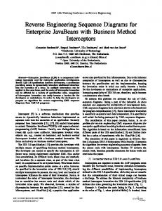
Figure 7: Rational Rose Diagram for C++. This figure shows the class diagram produced by the Rational Rose tool using the C + + example of Figure 4.
the application. This inference mechanism allows the user to ignore standard Java library classes when creating the model. This tool also infers multiplicity and mutability depending on how the fields of an object are used. Rational Rose C++ Demo 4.0.3 is a model driven software development tool. The models used in this tool are based on UML. The Rose C++ analyzer requires the user to set up the appropriate environment identifying all the directories containing the files required for analysis. Before the design is exported, the user chooses the level of detail required in the model. The model exported to Rose contains a logical view and a component view. The logical view consists of class diagrams for each package, as well as detailed specifications for each class. The component view shows the dependencies between the packages and classifies packages as either an interface or an implementation. Together is a comprehensive end-to-end ModelBuild-Deploy development platform for building enterprise solutions. Together provides the following services: creation and editing of several types of diagrams including UML diagrams, synchronization between design and implementation code (round-trip engineering), offers a workbench for writing code and integrates with different version control systems. 6.2
Comparison of the Tools
Since SuperWomble will only accept Java byte code, we translated the C + + example of Figure 4 into Java. The Java version of the example does not contain any stand-alone functions or friend functions, and namespace Security was replaced by the Java package Security. Thus, for our comparison, we use a Java version of the example for SuperWomble, and
Figure 8: Together Diagram for C++. This figure shows the class diagram produced by the Together tool using the C + + example of Figure 4.
the C + + version for Rational Rose, Together and Reveal. Figure 6 shows the class diagram produced by Reveal, Figure 7 shows the class diagram produced by Rational Rose, Figure 8 shows the class diagram produced by Together, and Figure 9 shows the class diagram produced by SuperWomble. All four of the tools show the inheritance relationship between classes Bank and Company in a similar manner. The Reveal, Rational Rose and Together representation of this inheritance relationship is consistent with the UML standard. Although the SuperWomble tool does not show a hollow arrow, this is likely an artifact of the graphviz drawing tool. The inheritance relationship between classes Customer and Person are also shown similarly. However, the Reveal representation of this inheritance shows a dashed line between Customer and Person; the dashed arrow in the Reveal diagram indicates that the relationship between Customer and Person as a realization(Rumbaugh, Jacobson & Booch 1999). Similarly, in the Together diagram, the Person class is underlined and the class name italicized, indicating that Person is an abstract base class. The Reveal, Rational Rose and Together tools also model the association between the classes Customer and BankAccount. Rational Rose and Together model this bi-directional relationship using two arrows, one for each of the dependencies. However, Reveal uses a more succinct notation, combining the bidirectional relationship into a single, undirected line between classes Customer and BankAccount. Reveal, Rational Rose and Together model the multiplicity of this relationship differently, yet each captures the fact that there is a single instance of Customer in BankAccount: Reveal adorns the undirected line with the number 1, Rational Rose adorns the directed line from BankAccount to Customer with the number 1.
Clarke, P. & Malloy, B. A. (2001), ‘A unified approach to implementation-based testing of classes’, Proceedings of 1st Annual International Conference on Computer and Information Science (ICIS ‘01) . Gamma, E., Helm, R., Johnson, R. & Vlissides, J. (1995), Design Patterns: Elements of Reusable Object-Oriented Software, Addison-Wesley. Institute, A. N. S. (1998), ISO/IEC JTC 1, number 14882:1998(E) in ‘ASC X3’, first edn, International Standard: Programming Languages - C++. Jackson, D. & Waingold, A. (2001), ‘Lightweight construction of object models from bytecode’, IEEE Transactions on Software Engineering . Josuttis, N. M. (1999), The C++ Standard Library, AddisonWesley. Koppler, R. (1997), ‘A systematic approach to fuzzy parsing’, Software – Practice and Experience 27(6), 637–649.
Figure 9: SuperWomble Diagram for Java. This figure shows the class diagram produced by the SuperWomble tool using a Java version of the example of Figure 4.
Together uses aggregation to show this multiplicity, indicating that the Customer, BankAccount relationship is a part-whole relationship. The Reveal, Rational Rose and Together tools also model class data attributes and member functions, including an indication of accessibility. We note that Reveal and Together are more resonant with the UML standard, using + and − to indicate public and protected; Reveal uses the # notation for protected. Rational Rose uses icons to model accessibility, which is inconsistent with the UML standard. SuperWomble provides an abbreviated version of the class diagram, which might be more useful for large programs with many classes; however, we note that SuperWomble does not include provision for the full class diagram. The Reveal diagram for class Customer indicates that the LENGTH data attribute is frozen (constant); this indication that LENGTH is constant is consistent with the UML standard; both Together and Rational Rose indicate this constness by attaching const as a prefix to the type of LENGTH, int. Finally, Reveal offers extensions to the UML class diagram to model namespaces, stand-alone functions and friend functions. However, the user may choose to turn this facility off, by de-selecting these extensions in the options menu of the GUI. 7
Concluding Remarks
We have presented our design and implementation of a tool, Reveal, to reverse engineer a UML class diagram for a C + + program. We have also presented extensions to the UML class diagram to accommodate namespaces, stand-alone functions and friend functions in the C + + language. We have compared Reveal to three other tools, Rational Rose, Together and SuperWomble, indicating compliance of the generated diagrams with the UML standard. References Asveld, P. (1995), ‘A fuzzy approach to erroneous inputs in context-free language recognition’, Proceedings of the 4th International Workshop on Parsing Technologies . Booch, G., Rumbaugh, J. & Jacobson, I. (1999), The Unified Modeling Language User Guide, Object Technology Series, Addison-Wesley.
Power, J. F. & Malloy, B. A. (2000), An approach for modeling the name lookup problem in the C + + programming language, in ‘ACM Symposium on Applied Computing’, Como, Italy. Power, J. F. & Malloy, B. A. (2001), Symbol table construction and name lookup in ISO C + +, in ‘Technology of ObjectOriented Languages and Systems, TOOLS 2000’, Sydney, Australia, pp. 57–68. Rumbaugh, J., Jacobson, I. & Booch, G. (1999), The Unified Modeling Language Reference Manual, Addison Wesley Longman, Inc. TogetherSoft (2001), ‘Together Control http://www.togethersoft.com/ .
Center
5.5’,
Wampler, B. (2001), ‘The V C++ GUI framework’, http://www.objectcentral.com .