Author manuscript, published in "5th European Conference of Software Architecture (ECSA) (2011) 220-235" DOI : 10.1007/978-3-642-23798-0_25
Reverse Engineering Architectural Feature Models Mathieu Acher1 , Anthony Cleve2 , Philippe Collet1 , Philippe Merle3 , Laurence Duchien3 , and Philippe Lahire1
inria-00614984, version 1 - 17 Aug 2011
1
Université de Nice Sophia Antipolis - I3S (CNRS UMR 6070), France {acher,collet,lahire}@i3s.unice.fr 2 PReCISE Research Centre, University of Namur, Belgium
[email protected] 3 INRIA Lille-Nord Europe, Univ. Lille 1 - CNRS UMR 8022, France {philippe.merle,laurence.duchien}@inria.fr
Abstract. Reverse engineering the variability of an existing system is a challenging activity. The architect knowledge is essential to identify variation points and explicit constraints between features, for instance in feature models (FMs), but the manual creation of FMs is both timeconsuming and error-prone. On a large scale, it is very difficult for an architect to guarantee that the resulting FM ensures a safe composition of the architectural elements when some features are selected. In this paper, we present a comprehensive, tool supported process for reverse engineering architectural FMs. We develop automated techniques to extract and combine different variability descriptions of an architecture. Then, alignment and reasoning techniques are applied to integrate the architect knowledge and reinforce the extracted FM. We illustrate the reverse engineering process when applied to a representative software system, FraSCAti, and we report on our experience in this context.
1 1.1
Introduction Problem
As a majority of software applications are now large-scale, business-critical, operated 24/7, distributed and ubiquitous, their complexity is increasing at a rate that outpaces all major software engineering advances. To tame it, Software Product Line (SPL) engineering is one of the major trends of the last decade. An SPL can be defined as "a set of software-intensive systems that share a common, managed set of features and that are developed from a common set of core assets in a prescribed way" [9]. SPL engineering aims at generating tailor-made variants for the needs of particular customers or environments and promotes the systematic reuse of software artifacts. An SPL development starts with an analysis of the domain to identify commonalities and variabilities (i.e., differences) between the members of the SPL. A common way is to describe variability of an SPL in terms of features, which are domain abstractions relevant to stakeholders. A Feature Model is used to compactly define all features in an SPL and their valid combinations [6,20,11].
inria-00614984, version 1 - 17 Aug 2011
2
Acher et al.
When SPL engineering is conducted right from the start on a software architecture, it is feasible to manage variability through one or more architectural feature models and then associate them to the software architecture [19]. The major architectural variations are then associated to some of the features and allows for some safe compositions in the architecture when features are selected to configure a software product from the line. One of the resulting properties of crucial importance is the guarantee that the variability is not only preserved but also kept consistent across all used artefacts [10,4,17]. But in many cases, legacy systems must be taken into account, or more often, the software system is developed incrementally. It is not a SPL at the beginning, but it becomes so complex, with many configuration and extension points, that its variability must be handled with SPL engineering techniques. In this context, the task of constructing feature models, which is intrinsically difficult, becomes very arduous for software architects, especially if they are presented with unrelated documents from which to derive the architectural feature model. It is then necessary to obtain a consistent feature model from the actual architecture. On a large scale both automatic extraction from existing parts and the architect knowledge should be ideally combined to achieve this goal.
1.2
FraSCAti: the Need for Handling Variability
In this paper, we illustrate our proposal and report on experiments with a case study on the FraSCAti platform [13]. It is an open-source implementation of the Service Component Architecture (SCA) standard [23], which allows for building hierarchical component architectures with the potential support of many component and service technologies. Started three years ago, the development of the FraSCAti platform begun with a framework, first validated by a basic implementation of the standard, and then incrementally enhanced. After four major releases, it now supports several SCA specifications (Assembly Model, Transaction Policy, Java Common Annotations and APIs, Java Component Implementation, Spring Component Implementation, BPEL Client and Implementation, Web Services Binding, JMS Binding), and provides a set of extensions to the standard, including binding implementation types (Java RMI, SOAP, REST, JSON-RPC, JNA, UPnP, etc.), component implementation types (Java, OSGi, Java supported scripting languages, Scala, Fractal), interface description types (Java, C headers, WSDL, UPnP), runtime API for assembly and component introspection/reconfiguration [21]. As its capabilities grew, FraSCAti has also been refactored and completely architected itself with SCA components. With all these capabilities, the platform has become highly (re-)configurable in many parts of its own architecture. It notably exposes a larger number of extensions that can be activated throughout the platform, creating numerous variants of a FraSCAti deployment. For example, some variations consist in one or more specific components bound to many other mandatory or optional parts of the platform architecture. It then became obvious to FraSCAti technical leads
Reverse Engineering Architectural Feature Models
3
that the variability 4 of the platform should be managed to pilot and control its evolution as an SPL. 1.3
Feature Modeling
The management and modeling of variability is a central activity in SPL engineering. We chose to rely on a particular kind of variability model, Feature Models (FMs), based on their wide adoption, the existence of formal semantics, reasoning techniques and tool support [6,20,11,7]. FMs compactly represent product commonalities and variabilities in terms of features. FMs can be used to describe software features at various levels of abstraction and thus can be used throughout the software lifecycle on different artefacts [10,16,4].
inria-00614984, version 1 - 17 Aug 2011
FM1
FraSCAti
SCAParser
Assembly Factory
Component Factory
Metamodel
Binding
Java Compiler
MMFrascati MMTuscany
http
rest
JDK6
constraints rest requires MMFrascati http requires MMTuscany
JDT
Optional
AlternativeGroup
Mandatory
Or-Group
(a) an excerpt of a possible architectural FM
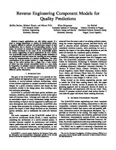
φ1 = F raSCAti ∧ F raSCAti ⇔ AssemblyF actory ∧ F raSCAti ⇔ ComponentF actory ∧ F raSCAti ⇔ SCAP arser ∧ SCAP arser ⇔ M etamodel ∧ AssemblyF actory ⇔ Binding ∧ ComponentF actory ⇔ JavaCompiler ∧ JavaCompiler ⇒ JDK6 ∨ JDT ∧ ¬ JDK6 ∨ ¬JDT ∧ M M F rascati ⇒ M etamodel ∧ M M T uscany ⇒ M etamodel ∧ http ⇒ Binding ∧ rest ⇒ Binding ∧ Binding ⇒ rest ∨ http ∧ rest ⇒ M M F rascati ∧ http ⇒ M M T uscany (b) propositional logic encoding
Fig. 1. Feature Model and Propositional Logic Encoding
FMs hierarchically structure application features into multiple levels of increasing detail. Fig. 1(a) shows an example of an FM. This FM is an extract of a architectural FM that is dedicated to the description of the FraSCAti platform, whereas FM are also widely used to capture and structure requirements. It must be noted that the FM that we discuss all along this paper are only architectural ones. As in typical SPLs, not all combinations of features or configurations (see Definition 1) are valid. Variability defines what the allowed configurations are. When decomposing a feature into subfeatures, the subfeatures may be optional, mandatory or may form Or or Alternative-groups (e.g., JDK6 and JDT form an Alternative-group, http and rest form an Or-group). An additional mechanism to specify variability is to add constraints (expressed in propositional logic), which may cut across the feature hierarchy (e.g., rest requires M M F rascati). The validity of a configuration is determined by the semantics of FMs, e.g. JDK6 4
We use here the term variability as in the definition from [24]: "software variability is the ability of a software system or artefact to be efficiently extended, changed, customized or configured for use in a particular context."
4
Acher et al.
and JDT are mutually exclusive and cannot be selected at the same time. A valid configuration is obtained by selecting/deselecting features from parents to children while following the rules imposed by the operators (e.g., exactly one subfeature must be selected in an Alternative) and the constraints. For example, {F raSCAti, SCAP arser, AssemblyF actory, ComponentF actory, M etamodel, M M F rascati, Binding, rest, JavaCompiler, JDT } is a valid configuration of the
FM shown in Fig. 1(a).
inria-00614984, version 1 - 17 Aug 2011
Definition 1 (SPL, Feature Model) A software product line SP Li is a set of products described by a feature model F Mi . The set of features of F Mi is denoted FF Mi . Each product of SP Li is a combination of features and corresponds to a valid configuration of F Mi . A configuration c of F Mi is defined as a set of features selected, i.e., c = {f1 , f2 , . . . , fm } ⊆ FF Mi . JF Mi K denotes the set of valid configurations of the feature model F Mi . We note φi the propositional formula of F Mi . The set of configurations represented by an FM can be described by a propositional formula defined over a set of Boolean variables, where each variable corresponds to a feature [6,11]. Figure 1(b) also shows the mapping of the FM to a propositional formula. The propositional formula can be used to automatically reason about properties of an FM (e.g., see [7]). In particular, if an assignment to its Boolean variables is satisfiable, then the selection/deselection of the corresponding features respects the rules evoked above. 1.4
Reverse Engineering FraSCAti as an SPL
In order to manage the FraSCAti platform as an SPL, we needed to capture its variability from the existing architecture. Several software artefacts (SCA composite files, Maven descriptors, unformal documents) describe FraSCAti architecture, but variability, though, is not explicitly represented.As the FraSCAti main software architect (SA) had an extensive expertise in the architecture and in its evolution, it was decided to make him model the architecture he has in mind with variation points (see left part of Fig. 2). As a domain expert, he had the ability to elicitate the architectural variation points and explain rationale behind these decisions. To follow separation of concerns principles, it was also decided to separate the variability description from the architectural model itself. The principle is to model the variation points of the architecture, to represent them as features in an architectural FM, and finally to describe the links between the features and the architectural elements. An important property is then to ensure consistency between FM and architectures [17], even if not all variability elements can be captured in an FM. This task resulted in a manually created FM and it was clearly daunting, time-consuming and error-prone, requiring substantial effort from the SA. In this case as in all large scale architectures, it is very difficult to guarantee that the resulting FM ensures a safe composition of the architectural elements when some features are selected. Another approach thus relies on an automated extraction, so that an architectural FM that represents variability of the architecture is automatically extracted from the appropriate artefacts (see right part
Reverse Engineering Architectural Feature Models
5
Software Artefacts
Variability Modeling Software Architect View
Automatic Extraction
?
inria-00614984, version 1 - 17 Aug 2011
Fig. 2. Variability Modeling from Software Artefacts
of Fig. 2).This operation clearly saves time and reduces accidental complexity, but the accuracy of the results directly depends on the quality of the available documents and of the extraction procedure. This approach is notably followed in recent reverse engineering work which is doing large scale variability extraction from the Linux kernel [22]. The main challenge is then to reconcile these two architectural FMs into a final FM being compatible with both the SA view and the actual architecture. It must also be noted that we could have tried to somehow integrate the SA knowledge in the extraction process or to let him edit an extracted FM, but we argue that keeping the first two activities separated was better. It lets a highly experienced SA focus on its own variability scoping, and compare it afterwards to the extracted version. Moreover, this allows for explicitly separating the required variability of the SA from the supported variability of the actual software system, as advocated in [18]. In this paper, we present a comprehensive, tool supported process for reverse engineering architectural FMs. We develop automated techniques to extract and combine different variability descriptions of an architecture. Then, alignment and reasoning techniques are applied to integrate the architect knowledge and reinforce the extracted FM. In the remainder of this paper we describe the automated extraction process that we have applied to FraSCAti FM(Section 2). We then show how the process is completed by refinement steps that enables the architect to compare and integrate his/her knowledge, so that a consistent architectural FM is obtained (Section 3). This process is validated by experiments on the FraSCAti architecture and some lessons learned are briefly discussed. Related work are studied in Section 4 while Section 5 concludes the paper.
2
Automatic Extraction of Architectural Feature Model
Overview. Fig. 3 summarizes the steps needed to realize the process. First, a raw architectural feature model, noted F MArch150 , is extracted from a 150% architecture of the system (see À). The latter consists of the composition of the architecture fragments of all the system plugins. We call it a 150% architecture because it is not likely that the system may contain them all. Consequently,
6
Acher et al.
inria-00614984, version 1 - 17 Aug 2011
F MArch150 does include all the features provided by the system, but it still constitutes an over approximation of the set of valid combinations of features of the system family. Indeed, some features may actually require or exclude other features, which is not always detectable in the architecture. Hence the need for considering an additional source of information. We therefore also analyze the specification of the system plugins and the dependencies declared between them, with the ultimate goal of deriving inter-feature constraints from inter-plugin constraints. To this end, we extract a plugin feature model F MP lug , that represents the system plugins and their dependencies (see Á). Then, we automatically reconstruct the bidirectional mapping that holds between the features of F MP lug and those of F MArch150 (see Â). Finally, we exploit this mapping as a basis to derive a richer architectural FM, noted F MArch , where additional feature constraints have been added. As compared to F MArch150 , F MArch represents much more accurately the architectural variability provided by the system. Software Artefacts 1
3
2
FMPlugin
FMArch 150
Mapping
150% Architectural FM
Aggregation
Plugin Dependencies
FMFull
Projection (Π) FMArch
Enforced Architectural FM
Fig. 3. Process for Extracting F MArch
2.1
Extracting F MArch150
The architectural FM extraction process starts from a set of n system plugins (or modules), each defining an architecture fragment. In order to extract an architectural FM representing the entire product family, we need to consider all the system plugins at the same time. We therefore produce a 150% architecture of the system, noted Arch150 . It consists of a hierarchy of components. In the SCA vocabulary, each component may be a composite, itself further decomposed into other components. Each component may provide a set of services, and may specify a set of references to other services. Services and references having compatible interfaces may be bound together via wires. Each wire has a reference
Reverse Engineering Architectural Feature Models
7
as source and a service as target. Each reference r has a multiplicity, specifying the minimal and maximal number of services that can be bound to r via wires. A reference having a 0..1 or 0..N multiplicity is called optional. Note that Arch150 may not correspond to the architecture of a legal product in the system family. For instance, several components may exclude each other because they all define a service matching the same 0..1 reference r. In this case, the architecture composition algorithm binds only one component service to r, while the other ones are left unbound in the architecture. Since the extracted architectural FM should represent the variability of the system of interest, we focus on its extension points, that are typically materialized by optional references in Arch150 . Algorithm 1 summarizes the behavior of the FM extractor. The root feature of the extracted FM (froot ) corresponds to the
inria-00614984, version 1 - 17 Aug 2011
Algorithm 1 ExtractArchitecturalF M150 (Arch150 ) Require: A 150% architecture of the plugin-based system (Arch150 ). Ensure: A feature model approximating the system family (F MArch150 ). 1: root ← M ainComposite(Arch150 ) 2: froot ← CreateF eature(root) 3: F MArch150 ← SetRootF eature(F MArch150 , froot ) 4: for all c ∈ F irstLevelComponents(root) do 5: fc ← CreateF eature(c) 6: F MArch150 ← AddM andatoryChildF eature(F MArch150 , froot , fc ) 7: F MArch150 ← AddChildF eatures(F MArch150 , c, fc , Arch150 ) 8: end for
main composite (root) of Arch150 . The child features of froot are the first-level components of root, the latter being considered as the main system features. The lower levels of child features are produced by the AddChildF eatures function (Algorithm 2). This recursive function looks for all the optional references r of component c and, for each of them, creates an optional child feature fr , itself further decomposed through a XOR or an OR group (depending on the multiplicity of r). The child features fcs of the group correspond to all components cs providing a service compatible with r. 2.2
Extracting F MP lug
The extraction of the plugin feature model F MP lug starts from the set of plugins P = {p1 , p2 , . . . , pn } composing the system. This extraction is straightforward: each plugin pi becomes a feature fpi of F MP lug . If a plugin pi is part of the system core, fpi is a mandatory feature, otherwise it is an optional feature. Each dependency of the form pi depends on pj is translated as an inter-feature dependency fpi requiresfpj . Similarly, each pi excludes pj constraint is rewritten as an excludes dependency between fpi and fpj . 2.3
Mapping F MArch150 and F MP lug
When producing Arch150 , we keep track of the relationship between the input plugins and the architectural elements they define, and vice versa. On this basis, we specify a bidirectional mapping between the features of F MArch150 and
8
Acher et al.
Algorithm 2 AddChildF eatures(F M, c, fp , Arch150 )
inria-00614984, version 1 - 17 Aug 2011
Require: A feature model (F M ), a component (c), a parent feature (fp ), a 150% architecture (Arch150 ). Ensure: F M enriched with the child features of fp , if any. 1: for all r ∈ OptionalRef erences(c) do 2: M C ← F indM atchingComponents(Arch150 , r) 3: if M C 6= ∅ then 4: fr ← CreateF eature(r) 5: F M ← AddOptionalChildF eature(F M, fp , fr ) 6: if M ultiplicy(r) = 0..1 then 7: g ← CreateXORGroup() 8: else if M ultiplicy(r) = 0..N then 9: g ← CreateORGroup() 10: end if 11: F M ← AddGroup(F M, fr , g) 12: for all cs ∈ M C do 13: fcs ← CreateF eature(cs ) 14: F M ← AddChildF eatureOf Group(F M, g, fcs ) 15: F M ← AddChildF eatures(F M, cs , fcs , Arch150 ) 16: end for 17: end if 18: end for
those of F MP lug by means of requires constraints. This mapping allows us to determine (1) which plugin provides a given architectural feature, and (2) which architectural features are provided by a given plugin. 2.4
Deriving F MArch
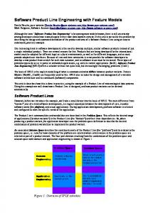
Semantics and Example. We now illustrate how we can derive F MArch using F MArch150 , F MP lug , the mapping between F MP lug and F MArch150 , and an operation called projection using the example of Fig. 4. First F MP lug and F MArch150 are aggregated under a synthetic root F tAggregation so that root features of input FMs are child-mandatory features of F tAggregation. The aggregation operation produces a new FM, called F MF ull (see Fig. 4). The propositional constraints that relate features of F MP lug to features of F MArch150 are also added to F MF ull . Definition 1 (Projection) The projection is a unary operation on FM written as Πf t1 ,f t2 ,...,f tn (F Mi ) where f t1 , f t2 , ..., f tn is a set of features. The result of a projection applied to an FM, F Mi , is a new FM, F Mproj , such that: JF Mproj K = { x ∈ JF Mi K | x ∩ {f t1 , f t2 , ..., f tn } } Second, we compute the projection (see Definition 1) of F MF ull onto the set of features of F MArch150 (i.e., FF MArch150 = {Arch, Ar1, . . . , Ar6}). The projection produces a new FM, called F MArch (see Fig. 4). Formally: ΠFF MArch
150
(F MF ull ) = F MArch
In the example of Fig. 4, the relationship between JF MF ull K and JF MArch K truly holds. We can notice that one configuration of the original F MArch150 has been removed, i.e., JF MArch150 K \ JF MArch K = {Ar1, Ar2, Ar3, Ar6, Arch}. The reason is that the projected F MArch contains an additional constraint Ar3 ⇒ Ar5, not originally present in F MArch150 . Similarly, the constraint Ar4 ⇒
Reverse Engineering Architectural Feature Models
9
Ar6 (grey tint in Fig. 4) can been deduced but is redundant with Ar3 ⇒ Ar5. As we will see in the experiments (next Section), such deductions can dramatically reduce the set of configurations of F MArch150 . FMFull FtAggregation
FMArch150
FMPlugin
Arch
Plugin
Ar1 Ar3
Pl1
Ar2 Ar4
Ar5
Ar6
Pl2 Pl1 => Pl2
Pl3
Ar3 => Pl1 Pl2 => Ar5
Projection (Π) onto Arch, Ar1, …, Ar6 FMArch Arch
inria-00614984, version 1 - 17 Aug 2011
Ar1 Ar3
Ar5
Alternative -Group
Mandatory
Or-Group
Ar3 => Ar5 Ar4 => Ar6
Ar2 Ar4
Optional
Ar6
Fig. 4. Enforcing architectural FM using aggregation and projection.
Implementation of the projection. Our previous experience in the composition of FMs has shown that syntactical strategies have severe limitations to accurately represent the set of configurations expected, especially in the presence of cross-tree constraints [1]. The same observation applies for the projection operation so that reasoning directly at the semantic level is required. The key ideas of our implementation are to i) compute the propositional formula representing the projected set of configurations and then ii) reuse the reasoning techniques proposed in [11] to construct an FM from the propositional formula. Formula Computation. For a projection F Mproj = Πf t1 ,f t2 ,...,f tn (F Mi ), the propositional formula corresponding to F Mproj is defined as follows5 : φproj ≡ ∃ f tx1 , f tx2 , . . . f txm0 φi where f tx1 , f tx2 , . . . f txm0 ∈ (FF Mi \ {f t1 , f t2 , . . . f tm }) = Fremoved . The propositional formula φproj is obtained from φi by existentially quantifying out variables in Fremoved . Intuitively, all occurrences of features that are not present in any configuration of F Mproj are removed by existential quantification in φi . The projection can be seen as a safe removal of a set of features (i.e., existential quantification removes a variable from a propositional formula without affecting its satisfiability). We rely on Binary Decision Diagrams (BDDs) to compute φproj [8]. A BDD can be seen as a compact representation of a propositional formula. Our choice to use BDDs was driven by several elements: i) computing the existential quantification of BDDs and several logical operations can be performed in at most 5
Let v be a Boolean variable occurring in φ. Then φ|v (resp. φ|v¯ ) is φ where variable v is assigned the value True (resp. False). Existential quantification is then defined as ∃v φ =def φ|v ∨ φ|v¯ .
inria-00614984, version 1 - 17 Aug 2011
10
Acher et al.
polynomial time with respect to the sizes of the BDDs involved [8]; ii) efficient optimized implementations of these operations are provided by off-the-shelf BDD libraries (e.g., we use the JavaBDD library [14]); iii) the techniques described in [11] (see below) also relies on a BDD-based implementation and iv) polynomial algorithms are available for computing valid domains or the counting of the number of products (see [7]). From Formula to FM. We use the algorithm presented in [11] to transform φproj into an FM. More precisely, the algorithm builds a tree with additional nodes for feature groups that can be translated into a basic feature diagram. Importantly, the algorithm indicates parent-child relationships (i.e., mandatory or optional features) and Alternative- or Or-groups. The feature diagram, however, is an over approximation of the original formula in the sense that if we translate the synthesized feature diagram to a propositional formula, noted φprojdiagram , then some valid assignments of φprojdiagram may be invalid in φproj (but any valid assignment of φproj is also valid in φprojdiagram ). We thus need to further constrain the feature diagram (as we did for the example of Fig. 4). We propose to decompose the FM F Mproj as a feature diagram, a set of require constraints and a set of other propositional constraints (that cut across the hierarchy of the diagram). We compute the set of require constraints by first computing the implication graph, noted Iproj , of the formula φproj over f t1 , f t2 , ..., f tn . Iproj is a directed graph G = (V, E) formally defined as: V = {f t1 , f t2 , ..., f tn }
E = {(fi , fj ) | φproj ∧ fi ⇒ fj }
Then, the set of require constraints can be deduced by removing edges from Iproj being already expressed in the feature diagram (e.g., parent-child relations). Finally, if the feature diagram plus the require constraints are still an over approximation of φproj (it is not the case in Fig. 4), an additional formula φprojother can be obtained so that φproj = φprojdiagram ∧ φprojrequires ∧ φprojother (φprojrequires being the logical conjunction of all require constraints of Iproj ).
3
Refining the Architectural Feature Model: Experiments
We conduct an experiment to i) determine if the architectural FM designed by the SA6 , noted F MSA , is consistent with the extracted FM F MArch (and vice-versa) ; ii) step-wise refine F MSA based on the previous observations. We describe the techniques developed for the experiment and analyze the results. 3.1 Tool Support For the experiment, we rely on FAMILIAR (FeAture Model scrIpt Language for manIpulation and Automatic Reasoning) [12,2], a domain-specific language dedicated to the management of FMs. FAMILIAR is an executable, textual language that supports manipulating and reasoning about FMs and is integrated in a comprehensive Eclipse-based environment (including graphical editors). We use FAMILIAR for two main purposes. Firstly, the extraction procedure generates FAMILIAR code to compute F MArch . Secondly, FAMILIAR provides the SA with a dedicated approach for easily manipulating FMs during the refinement process. 6
Philippe Merle, co-author of this paper and principal developer of FraSCAti, plays the role of software architect (SA) in the experiment.
Reverse Engineering Architectural Feature Models
3.2
11
Experimental Results
Automatic Extraction. The F MArch150 produced by the extraction procedure7 contains 50 features while the F MP lug contains 41 features. The aggregated FM, F MF ull , resulting from F MArch150 , F MP lug and the bidirectional mapping contains 92 features and 158 cross-tree constraints. We first verify some properties of F MF ull . By construction, we know that the projection of F MF ull onto FF MArch150 is either a refactoring or a specialization8 of F MArch150 (see Definition 2).
inria-00614984, version 1 - 17 Aug 2011
Definition 2 (Specialization, Refactoring, Generalization, Arbitrary Edit) Let f and g be two feature models. f is a specialization of g if Jf K ⊂ JgK f is a generalization of g if JgK ⊂ Jf K f is a refactoring of g if JgK = Jf K f is an arbitrary edit of g if f is neither a specialization, a generalization nor a refactoring of g. Our experiments reveal that F MArch is a specialization of F MArch150 . More precisely, F MArch150 admits 13958643712 possible configurations (≈ 1011 ), while F MArch represents 936576 distinct products (≈ 106 ). As expected, the projection technique significantly reduces the over approximation of F MArch150 . To improve the understanding of the difference between two FMs, we use a diff operator, denoted as F M1 ⊕\ F M2 = F Mr . The following defines the semantics of this operator. JF M1 K \ JF M2 K = {x ∈ JF M1 K | x ∈ / JF M2 K} = JF Mr K The formula φr of F Mr is used to reason about properties of F Mr (e.g., satisfiability) and is computed as follows: φr = (φF M1 ∧ not(FF M2 \ FF M1 )) ∧ ¬(φF M2 ∧ not(FF M1 \ FF M2 )) For example, determining the kind of relationship between two FMs (see Definition 2) can be done by reusing the algorithm presented in [25] or by using the diff operator (see Definition 3). Definition 3 (Diff and Specialization/Refactoring) Let f and g be FMs. f is a specialization or a refactoring of g if (f ⊕\ g) has no valid configurations since Jf K ⊆ JgK is equivalent to Jf K \ JgK = ∅. Moreover, the diff operator can compute the difference (if any) between two FMs in terms of set of configurations. In particular, we can compute the cardinality of this set. For example, we correctly check the following relationship9 using the tool support: |F MArch150 | - F MArch150 ⊕\ F MArch = |F MArch |. Techniques for Refining Architectural FM. The goal of the reverse engineering process is to elaborate an FM which accurately represents the valid combinations of features of the SPL architecture. The absence of a ground truth FM (i.e., an FM for which we are certain that each combination of features is 7
8 9
material, details and results of the experiments are accessible at https://nyx. unice.fr/projects/familiar/wiki/ArchFm We rely on the terminology used in [25]. where |F Mi | denotes the number of configurations of F Mi , i.e., |F Mi | = |JF Mi K|
12
Acher et al.
supported by the SPL architecture) makes uncertain the accuracy of variability specification expressed in F MArch as well as in F MSA . It is the role of the SA to determine if the variability choices in F MSA (resp. F MArch ) are coherent regarding F MArch (resp. F MSA ). In case variability choices are conflicting, the SA can refine the architectural FM.
inria-00614984, version 1 - 17 Aug 2011
We now report the problems encountered when reasoning about the relationship between F MArch and F MSA . We also describe the advanced techniques we developed to assist the SA. Reconciling F MArch and F MSA . A first obstacle concerned the need to reconcile F MArch and F MSA (see Fig. 5). Both FMs come from difference sources and a preliminary work is needed before reasoning about their relationship. Firstly, the vocabulary (i.e., names of features) used differs in both FMs and should be aligned consequently. To resolve this issue, we rely on string matching techniques (i.e., Levenshtein distance) to automatically identify features of F MArch that correspond to features of F MSA . Then a renaming is applied on all corresponding features in F MArch . As an example, "MMFraSCAti” of F MSA has been identified to correspond to "sca_metamodel_frascati” of F MArch and after the renaming F MArch contains the feature "MMFraSCAti”. We automatically detect 32 features. The SA manually specifies the correspondence for 5 features in which the automated detection does not succeed (e.g., "MembraneFactory" corresponding to "fractal_bootstrap_class_providers"). Secondly, granularity details differ, (i.e., some features in one FM are not present in the other FM): F MSA only contains 39 features whereas F MArch contains 50 features. In F MSA but not in F MArch . Two exclusive features F elix and Equinox are present in F MSA but not in F MArch . We also observed that the two features are present in F MP lug but not in F MArch150 (and hence not in F MArch ). A discussion with the SA reveals that these two plugins do not explicitly define architecture fragments in SCA. As a consequence, this variability point can simply not be identified in the architecture by the automatic extraction procedure. In F MArch but not in F MSA . We identified 13 features that are present in F MArch but not in F MSA . Among others, two Metamodels used by the SCA parser, three Bindings, two SCA properties, two Implementations and one Interface were missing. Given the complexity of the FraSCAti project, this is not surprising that the SA forgets some features. Hence, for most of the features, the SA considers the missing features as relevant and thus adds them in F MSA . For one of the missing feature, "sca_interface_java", the SA reveals that he intentionally ignored it in F MSA , arguing that it is a mandatory feature (i.e., every FraSCAti configuration has a Java interface) and that his focus was on variability rather than commonality. We indeed verify the mandatory nature of "sca_interface_java" in F MArch . Nevertheless, the SA decides to add "sca_interface_java" in F MSA . Similarly, two first-level mandatory features, "binding_factory” and "services", were missing in F MSA . The SA intentionally did not include the two features since they do not convey any further variation points, but he decides to edit F MSA by adding those features. Another example concerns a feature of F MArch , "juliac", that adds unnecessary details (so that
Reverse Engineering Architectural Feature Models FMArch
FMSA
Enforced Architectural FM
Reconciling Feature Models
renaming, projection, removal
13
Software Architect View
renaming, projection, removal
(e.g., vocabulary and granularity alignment)
Aligned Architectural FM
Aligned Software Architect View
FMArch’
FMSA’
Comparison
inria-00614984, version 1 - 17 Aug 2011
Refined Archiectural FM
More refinement
Fig. 5. Process for Refining F MArch
the way features are organized in F MSA and F MArch slightly differ). Here the SA decides to remove "juliac" by projection. Reasoning about F MArch and F MSA . At this step, we can compare F MArch and F MSA . A first comparison is to determine the kind of relationship between F MArch and F MSA (see Definition 2). We obtain an arbitrary edit, that is, some configurations of F MArch are not valid in F MSA (and viceversa). To go further, we use the diff operator (see Definition 3) and the merge in intersection mode (see [1]). We enumerate and count the unique configurations of F MArch and F MSA as well as the common configurations of F MArch and F MSA . Nevertheless, the techniques appear to be insufficient to really understand the difference between the two FMs. Intuitively, we need to identify more local differences. A first technique is to compare the variability associated to features of F MArch and F MSA that have the same name. In particular, we detect that i) four features are optional in F MArch but mandatory in F MSA and ii) three sets of features belong to Or-groups in F MArch whereas in F MSA , the features are all optional. A second technique is to compute the intersection and the difference of the sets of require constraints in F MArch and F MSA (based on their implication graphs, see page 10). Step-wise Refinement of F MSA . The comparison techniques have been reiterated until having a satisfying architectural FM. Based on the comparison results, the SA have had several attitudes. Firstly, he used F MArch to verify the coherence of his original variability specification in F MSA . Secondly, he considered that some variability decisions in F MSA are correct despite their differences with F MArch . The SA imposed five variability decisions not identified by the extraction procedure. Thirdly, he edits F MSA , for example, by adding some constraints only present in F MArch or by setting optional a feature originally mandatory. The extracted FM notably identifies nine "obvious" constraints not expressed in F MSA and allows the SA to incrementally correct F MArch .
14
inria-00614984, version 1 - 17 Aug 2011
3.3
Acher et al.
Lessons Learned
The FraSCAti experiment provide us with interesting insights into the reverse engineering of architectural FMs. First, the gap between F MSA and F MArch appears to be manageable, due to an important similarity between the two FMs. However, it remains helpful to assist the SA with automated support, in particular, to establish correspondences between features of the two FMs. The most time-consuming task was to reconcile the granularity levels of both FMs. For this specific activity, tool supported, advanced techniques, such as the safe removal of a feature by projection, are not desirable but mandatory (i.e., basic manual edits of FMs are not sufficient). Second, our extraction procedure (Section 2) yields very promising results. It recovers most of the variability expressed in F MSA and encourages the SA to correct his initial model. A manual checking of the five variability decisions imposed by the SA shows that the extraction is not faulty. It correctly reproduces the information as described in the software artefacts of the project. Third, the SA knowledge is required i) to scope the SPL architecture (e.g., by restricting the set of configurations of the extracted FM), especially when software artefacts do not correctly document the variability of the system and ii) to control the accuracy of the automated procedure. An open issue is then to provide a mechanism and a systematic process to reuse the SA knowledge, for example, for another version of the architectural FM of FraSCAti.
4
Related Work
Despite the importance of variability management in software engineering in general, and in software architectures in particular [5], the problem of reverse engineering the variability of existing systems has definitely not received sufficient attention from the research community. While our work takes an architectural perspective, the other existing approaches in the field consider different input artifacts including legacy system documentation [15] or textual requirements [3,26]. In their recent work, She et al. [22] propose a reverse engineering approach combining two distinct sources of information: textual feature descriptions and feature dependencies. Our approach also benefits from the combination of two (other) sources of information, namely plugin dependencies and architecture fragments. They mostly focus on the retrieval of the feature diagram (heuristics for identifying the most likely parent feature candidates of each feature, group detection, etc.) and assume that the set of valid configurations is correctly restituted, which is clearly not the case in our work. We also support the identification of feature groups (based on architectural extension points), of the right parent feature of each feature (based on architectural hierarchy) and of inter-feature dependencies (through projection of plugin dependencies). The FM analysis and reasoning techniques used in this paper reuse and extend previous work in SPL and requirement engineering [7]. Metzger et al. [18] propose an approach to cross-checking product-line variability and software variability models, thus assuming that such models (or views) are available. Our approach is complementary since it allows to recover the actually supported variability of a software system, and since it involves the cross-analysis of architec-
inria-00614984, version 1 - 17 Aug 2011
Reverse Engineering Architectural Feature Models
15
tural and plugin FM. One of the key component and original contribution of our work is the projection operator we have defined and realized (see Section 2). Lopez and Eyged [16] address a related problem in the context of safe composition by checking the consistency of multi-view variability models. In particular, they check whether an FM developed by a domain expert is a specialization or a refactoring of an FM representing the variability of multiple models. Thüm et al. [25] reason on the nature of FM edits, and provide a classification that we rely on when comparing the extracted FM with the software architect view. The diff operator provides a compact representation of all added and removed configurations and is an extension of their work. As we have shown, reasoning about the relationship of two FMs is inappropriate until FMs are not reconciled, i.e., pre-directives (e.g., safe removal of unnecessary details) have to be applied before. The comparison operator developed in [25] considers only the concrete features (i.e., leaves) but our experience shows that it is important to consider all features of the two FMs (e.g., a non leaf feature can be concrete). Benavides et al. compared the performance of CSP, SAT solvers and BDD solvers for some reasoning operations on FMs [7]. As future work, we will investigate the use of SAT or CSP solvers to realize the diff/projection operators. A comparison with BDD-based implementations is planned to determine the most scalable solution. Another research direction is to consider feature attributes [7], for example, to model quality attributes of the FraSCAti architecture.
5
Conclusion
Variability management is of crucial importance in the management of large families of software systems. While feature models have long been recognized as expressive means to compactly represent software variability from different perspectives, building one of them for a large system is a complex, time-consuming and error-prone activity. In this paper, we presented a tool-supported approach to reverse engineer software variability from an architectural perspective. The reverse engineering process involves the automatically supported extraction, aggregation, alignment and projection of architectural feature models. It has the merit of combining several sources of information, namely software architecture, plugin dependencies and software architect knowledge. We successfully evaluated the proposed approach when applied to FraSCAti, a large and highly configurable plugin-based system. We showed that our automated procedures allow for producing both correct and useful results, thereby significantly reducing manual effort. We learned, however, that fully automating the process is not realistic nor desirable, since the intervention of the software architect remains highly beneficial. The ongoing evolution of the FraSCAti project will bring us an opportunity to study how to reuse the accumulated knowledge of the software architect and provide a validated, systematic process for extracting architectural variability models.
References 1. M. Acher, P. Collet, P. Lahire, and R. France. Comparing Approaches to Implement Feature Model Composition. In ECMFA’10, volume 6138 of LNCS, pages 3–19, 2010.
inria-00614984, version 1 - 17 Aug 2011
16
Acher et al.
2. M. Acher, P. Collet, P. Lahire, and R. France. A Domain-Specific Language for Managing Feature Models. In SAC’11. PL Track, ACM, 2011. 3. V. Alves, C. Schwanninger, L. Barbosa, A. Rashid, P. Sawyer, P. Rayson, C. Pohl, and A. Rummler. An exploratory study of information retrieval techniques in domain analysis. In SPLC’08, pages 67–76. IEEE, 2008. 4. S. Apel and C. Kästner. An overview of feature-oriented software development. Journal of Object Technology (JOT), 8(5):49–84, July/August 2009. 5. F. Bachmann and L. Bass. Managing variability in software architectures. SIGSOFT Softw. Eng. Notes, 26:126–132, May 2001. 6. D. Batory. Feature models, grammars, and propositional formulas. In Proc. of SPLC’2005, volume 3714 of LNCS, pages 7–20. Springer, 2005. 7. D. Benavides, S. Segura, and A. Ruiz-Cortes. Automated Analysis of Feature Models 20 years Later: a Literature Review. Information Systems, 2010. 8. K. S. Brace, R. L. Rudell, and R. E. Bryant. Efficient implementation of a bdd package. In DAC’90, pages 40–45. ACM, 1990. 9. P. Clements and L. M. Northrop. Software Product Lines : Practices and Patterns. Addison-Wesley Professional, 2001. 10. K. Czarnecki and K. Pietroszek. Verifying feature-based model templates against well-formedness ocl constraints. In GPCE’06, pages 211–220. ACM, 2006. 11. K. Czarnecki and A. Wasowski. Feature diagrams and logics: There and back again. In SPLC’07, pages 23–34, 2007. 12. FAMILIAR. http://nyx.unice.fr/projects/familiar/. 13. FraSCAti. https://wiki.ow2.org/frascati/Wiki.jsp?page=Main. 14. JavaBDD. http://javabdd.sourceforge.net/index.html. 15. I. John. Capturing product line information from legacy user documentation. In Software Product Lines, pages 127–159. Springer, 2006. 16. R. E. Lopez-Herrejon and A. Egyed. Detecting inconsistencies in multi-view models with variability. In ECMFA’10, pages 217–232, 2010. 17. R. E. Lopez-Herrejon and A. Egyed. On the need of safe software product line architectures. In ECSA’10, volume 6285 of LNCS, pages 493–496. Springer, 2010. 18. A. Metzger, K. Pohl, P. Heymans, P.-Y. Schobbens, and G. Saval. Disambiguating the documentation of variability in software product lines: A separation of concerns, formalization and automated analysis. In RE’07, pages 243–253, 2007. 19. C. A. Parra, A. Cleve, X. Blanc, and L. Duchien. Feature-based composition of software architectures. In ECSA’10, volume 6285 of LNCS, pages 230–245. Springer, 2010. 20. P.-Y. Schobbens, P. Heymans, J.-C. Trigaux, and Y. Bontemps. Generic semantics of feature diagrams. Comput. Netw., 51(2):456–479, 2007. 21. L. Seinturier, P. Merle, D. Fournier, N. Dolet, V. Schiavoni, and J.-B. Stefani. Reconfigurable SCA Applications with the FraSCAti Platform. In SCC’09, pages 268–275. IEEE, 2009. 22. S. She, R. Lotufo, T. Berger, A. Wasowski, and K. Czarnecki. Reverse engineering feature models. In ICSE’11, 2011. to appear. 23. SCA standard. http://www.osoa.org/. 24. M. Svahnberg, J. van Gurp, and J. Bosch. A taxonomy of variability realization techniques: Research articles. Softw. Pract. Exper., 35(8):705–754, 2005. 25. T. Thüm, D. Batory, and C. Kästner. Reasoning about edits to feature models. In ICSE’09, pages 254–264. IEEE, 2009. 26. N. Weston, R. Chitchyan, and A. Rashid. A framework for constructing semantically composable feature models from natural language requirements. In SPLC’09, volume 446 of ICPS, pages 211–220. ACM, 2009.