Reversible Binary Image Data Hiding By Run-Length Histogram Modification Guorong Xuan1, Yun Q. Shi2, Peiqi Chai1 , Xuefeng Tong1, Jianzhong Teng1, Jue Li1 1 Dept. of Computer Science, Tongji University, Shanghai, China 2 Dept. of ECE, New Jersey Institute of Technology, Newark, New Jersey, USA
[email protected],
[email protected] Abstract. A novel reversible binary image data hiding scheme using run-length (RL) histogram modification is presented in this paper. The binary image is scanned from left to right and from top to bottom to form a sequence of alternative black RL and white RL. Combining one black RL and its immediate next white RL, we form one RL couple, thus generating a sequence of RL couples. The length of each couple is fixed during data embedding in order not to fail the reversibility. Two procedures are adopted to achieve reversibility: 1) only involve those RL couples in data embedding in which the length of couple is not shorter than threshold T1; 2) increase white RL of isolated white pixels from one to two. Another parameter T indicates where to embed data in black RL histogram. Adjusting T1 and T may result in optimum performance of pure embedding rate versus visual quality of marked image. The proposed scheme works for text, graphics, and their mixture, both halftone and non-halftone binary images. Experimental works have shown its superior performs over the prior-arts.
1 Introduction There are only a rather limited number of reversible binary image data hiding schemes in the literature [1,2,3]. To our best knowledge, none of them can be applied to all types of binary images: text, graph, and their mixture, halftone and non-halftone. A novel approach to reversible binary data hiding that can be applied to all the above-mentioned types of binary images using run-length (RL) histogram modification is presented in this paper. In this new approach, the cover binary image is scanned, RLs of the binary image are derived; the RL histogram is modified to embed data reversibly. Specifically, the histogram-pair based reversible image data hiding scheme [4] is applied to the black RL histogram. The issue of isolated white pixels in the cover binary image, that may defeat reversibility, is analyzed. One measure relying on manipulating both black and white RLs has been proposed and used in our experimental works to reliably solve the isolated white pixel issue. In this paper we term the combination of the histogram-pair operation and the black and white RL manipulation (used to eliminate isolated white pixels), which results in the RL histogram change, as histogram modification. The RL histogram modification is thus the major feature of our novel approach to reversible binary image data hiding.
Our experimental works have demonstrated the superior performance in reversible binary image data hiding over the existing technologies. The rest of this paper is organized as follows. In Section 2, the proposed scheme is illustrated via two examples. The block diagram is presented in Section 3. Section 4 reports some experimental works. Conclusion is drawn in Section 5.
2. Run-Length Histogram Modification In this section, two simple binary images are used to illustrate the proposed scheme. 2.1 A simple example A. Data embedding A binary image of two-row and 15-column is shown in the right side of Part I of Table 1, where 0 and 1 are used to denote white pixel and black pixel, respectively. The black and white RL histograms, and the RL couples of the binary image are shown in the left side of Part (I). In forming the black and white runs, the scanning is conducted from left to right and from top to bottom. That is, we link row x1’s end with the head of row x2 forming a 1-D sequence, then we determine the black and white RLs. Furthermore, along the scan sequencing, we combine a black RL and its immediately next white RL to form a RL couple; all of the RL couples form the RL couple sequence. Table 1
A simple example
It is observed that the black RL histogram in Part I is: h(1)=4, h(2)=1, h(3)=2. Therefore, we need to create a histogram-pair for data embedding. Let us choose to embed data into black RL equal to 1, i.e., we set a parameter T=1. Since h(1)=4, four bits may be embedded. To embed data, we need to create a histogram-pair [4], [h(1)=4, h(2)=0]. To do so, we scan row x1, followed by row x2, searching for the black RL of 2, i.e., two consecutive black pixels. It is found that
these two consecutive black pixels are in row x1 (columns 11 and 12). We then extend this black RL from 2 to 3, thus causing h(2)=0 and h(3)=4. The change needs to be recorded as bookkeeping for future original image recovery. Note that this change makes the white RL following the changed black RL to decrease by 1. That is, the sum of the black RL and the white RL in this RL couple remains unchanged. The modified image, RL couple sequence, and black and white RL histograms are shown in Part II of Table 1. With the histogram-pair created, now we are ready for data embedding. Since h(1)=4, we can embed four bits and assume we want to embed the following four bits: 1,0,11. We then scan the binary image as shown at the right side of Part II. When we meet the first black pixel with RL being 1 (row x1, column 1), examine the first to-be embedded bit, which is 1, we then change the pixel at row x1 and column 2 from 0 to 1 in order to change the black RL from 1 to 2. Consequently the corresponding white RL is reduced by 1. We then move to the next single black pixel (row x1 and column 4), since bit 0 is to be embedded, we do not change anything. We then scan for the 3rd single black pixel, which is located at row x1 and column 8, since bit 1 is to be embedded, we change the white pixel (row x1, column 9) to black. For the next single black point at row x2 and column 1, since bit 1 is to be embedded, we change its next white pixel (row x2, column 2) to 1. The resultant binary image after data embedding is shown at right side of Part III, its RL couple sequence and RL histogram are shown at the left side of Part III. B. Data extracting At this stage, what left is the marked image, i.e., the image with the hidden data, which in this example is shown the right side of Part III in Table 1. We use the same sequencing as used in data embedding to check each pixel. When a black RL of 1 is encountered, we extract a bit 0, when a black RL 2 is encountered, a bit 1 is extracted and the black RL 2 is changed back to RL 1. In this way we can extract hidden data and recover the original binary image. Note that the bookkeeping data is used for image recovery. 2.2 Another more general example Another example is shown in Table 2. To be brief, we discuss here only the steps/issues which have not been addressed in Table 1 of the previous example. A. Data embedding Since the consecutive white pixels at the beginning of the first row of the binary image and the consecutive black pixels at the end of the last row of an image are not used for data embedding, in the right side of Part II of Table 2, two white pixels at the beginning of the first row and one black pixel at the end of the second row are made empty. The corresponding black and white RL histograms and the sequence of RL couples are shown at the left side of Part II.
In this proposed scheme there is a threshold, T1, which is defined as such a sum of the black and white RLs within one RL couple that those RL couples, whose sum of black and white RLs is short than T1, will not be used for data embedding. The reason of doing so is to eliminate isolated white pixels (white RL being 1), which may defeat reversibility, i.e., the original image cannot be received exactly. Consider a RL couple , which corresponds to one black pixel followed by one white pixel . If the black pixel is used to embed bit 1, this black RL will increase by 1 and the white RL will change from 1 to 0. Consequently, this new black run (with RL being 2) will touch the black RL in the next RL couple. Hence, no way to extract hidden data correctly and to recover original cover image reversibly. Therefore, the least value that T1 can take is 3. Here, we take T1=3. From this consideration, two RL couples: and in row x1 will not be used for data embedding. Hence, the corresponding four pixels have been removed in the right side of Part III. The updated RL couple sequence and RL histograms are shown in the left side of the part. Table 2 Another example
Examination of the resultant binary image at the right side of Part III reveals that there is an isolated white pixel at row x2 and column 14. (Note that the sum of black RL (ahead of this isolated white pixel) and this white RL (being 1) is 3, equal to the minimum allowed T1 value.) According to the analysis made in the above paragraph, we have to eliminate this isolated white point for the sake of reversibility. We hence change the black pixel immediately ahead of this isolated white pixel to a white pixel as shown at the right side of Part IV of Table 2. As a result, the RL
couple changes from to , indicating that the sum of the black and white RLs in the RL couple remains unchanged. The RL couple sequence and RL histogram are shown at the left side of Part IV. This modification is recorded and will be used late for original image recovery. In our proposed scheme, two parameters, T1 and T, are selected for the optimal data embedding. B. Data extracting Because we do not consider the consecutive white pixels at the beginning and the consecutive black pixels at the end in data embedding, and T1 is known as 3, we can easily derived the image shown at the right side of Part VI. From the image in Part VI, we can easily come up with the associated RL and histogram of RL, as shown at the left side of Part VI. Because T is known as 1, we examine one by one all of the black runs in the same order as in data embedding, i.e., from left to right, from top to bottom, whenever a black RL 1 is encountered, we extract a bit 0, whenever a black RL 2 is encountered, we extract a bit 1. In this way, we extract a bit sequence of “1,0,1,1”. Furthermore, whenever we extract a bit 1, we need to reduce the corresponding black RL 2 to 1 (hence, white RL is added by 1). In this way, we can recover the binary image as shown in the right side of Part V. Because in data embedding we created the histogram-pair [h(1)=4,h(2)=0] from Part IV to part V, now we can change black pixel at row 2 and column 3 to white pixel, thus deriving the binary image shown in the right side of Part IV. Because the record of isolated white point elimination is available, we can recover binary image shown in Part III. By adding back the image portions which correspond to those RL couple with the sum of black and white RL less T1=3, we can derive the binary image in Part II. By adding those consecutive white RL at the beginning and those consecutive black RL at the end, we recover the original image exactly as shown in Part I. Hence it is clear that in addition to payload, we need to embed bookkeeping data that is needed for exact recovery of original cover image.
computational search for the maximum embedding capacity.
Fig.1 Flowchart of proposed reversible binary image data embedding scheme
4.
Experimental Results
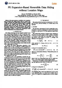
A. Mickey binary image In [1], the authors embedded 128 bits into the binary Mickey image of 274 × 312, resulting in 496 pixels which have been changed after data embedding. We applied the proposed method to embed 128 information bits (in addition to the bookkeeping data) into the same Mickey image (Fig.2(a)), resulting in 137 changing pixels in the marked image (Fig.2(b)). The changing pixels are shown in red in Fig.2(c). Table 3
274×312 non-halftone Mickey binary image
Capability (bit) (Bookkeeping not included) 100 128 200 432 2357
Number of changed pixels 96 137 245 653 2836
Bookkeeping (bits) 0 0 0 11 130
More experimental results on Mickey image are shown in Table 3.
3. Block Diagram The block diagram of the proposed scheme is shown in Fig. 1. There, RL stands for run-length, WRL for white RL, and BRL for black RL. T1 is a threshold such that a RL will not be used for reversible data hiding if the sum of BRL and WRL within the RL couple is smaller than T1. As analyzed in Section 2, the minimum value that T1 can take for reversible data hiding is 3. Another parameter T indicates where data is embedded. That is, the histogram-pair is created as [h(T),h(T+1)=0]. The to-be embedded data is then embedded into this histogram-pair. As discussed in Section 2, T1 and T parameters can be selected via
(a) Original
Fig. 2
(b) 128 bits embedded (c) 137 (red) pixels changed
Binary Mickey image of 274×312
B. (Non-Halftone) Binary Baboon image This binary image of 512×512, Fig. 3(a), is obtained by applying im2bw in Matlab to grayscale Baboon image. The 1063 bits has been embedded in
Fig. 3(b). The amount of bookkeeping data, 230 bits, is excluded from the payload of 1063 bits. There are 1694 pixels in the marked image which are different from the original binary image, as shown in Fig. 3(c) in red.
(a) Original
(b) Marked
(c) Changed pixels (red)
Fig. 3 Baboon non-halftone binary image of 512×512 C. Halftone Baboon image
The halftone Baboon image of 512×512, Fig. 4(a) is obtained by applying dither operation in Matlab to grayscale Baboon image. In Fig. 4(b), the total number of 7699 bits has been embedded at one time, excluding the bookkeeping data of 1491 bits. There are 6787 pixels that have changed during the data hiding as shown in Fig. 4(c) in red.
(a) Original
(b) Marked
(c) Changed pixels (red)
Fig. 4 Baboon halftone binary image of 512×512. D. Halftone NJIT 125th Anniversary image The NJIT 125th Anniversary binary image of 2520×3274 is obtained by scanning the original hardcopy, which contains both image and text. The total number of 23801 bits has been embedded, excluding the bookkeeping data of 1845 bits. There are 20555 pixels that have changed during the data hiding. A portion of 640×560 (1151 pixels changed), quoted from the NJIT 125th Anniversary binary image, is shown in Fig. 5.
(a) Original
(b) Marked
(c) changed(red)
Fig. 5 A portion of 640×560 quoted from NJIT 125th Anniversary binary image. E. Performance comparison with state of the arts As shown above, our method outperforms [1] in that when embedding the same amount of 128 bits into the same Mickey binary image, the number of changed pixels due to data embedding by our method is 137
pixels, while it is 496 pixels for [1]. Further more, each changing bit caused by our method is located at the end of a black RL. It is hence expected that the visual quality of marked image generated by our method is higher than [1]. According to [3], their method can embed 1941 or 2572 bits into non-halftone Baboon binary image, while our method can embed from 1063 to 6352 bits to the same image. Besides, it is not reported in [3] that their method can be applied to halftone binary images, while our method has been successfully applied to both non-halftone and halftone Baboon image. The method in [2] works well in halftone images, but not well for non-halftone binary images. Furthermore, only the capacity of 128 bits is reported in [2] as authors claimed that 128 bits are enough for authentication application.
5. Conclusion A novel approach to reversible binary image data hiding is presented, which is based on run-length (RL) histogram modification. The reversibility is achieved by embedding data only into those RL couples, whose sum of black and white RLs is not shorter than three, and then eliminating isolated white pixels with the necessary bookkeeping data. Compared with the existing reversible binary image data hiding schemes, this new scheme 1) can be applied to all types of binary images: text, graph, mixture of text and graph, halftone and non-halftone binary images; 2) can achieve better performance in terms of pure payload versus visual quality of marked image because it causes less changed pixels, and each changing bit is located at the end of a black RL, and this does not cause annoying effect from human vision point of view; 3) can generally embed a larger amount of data into the binary images than all of the existing reversible binary image data hiding schemes.
References [1] S. V. D. Pamboukian and H. Y. Kim, “Reversible data hiding and reversible authentication watermarking for binary images,” in VI Simpósio Brasileiro em Segurança da Informação e de Sistemas Computacionais (SBSeg), Santos, SP, Brasil, 2006. [2] J. S. Pan, H. Luo, and Z. M. Lu, “A lossless watermarking scheme for halftone image authentication,” International Journal of Computer Science and Network Security, vol.6 no.2b, Feb. 2006:147-151. [3] C. C. Wang, C. C. Chang, X. Zhang, and J. K Jan. Senary Huffman Compression - A Reversible Data Hiding Scheme for Binary Images. International Workshop on Multimedia Content Analysis and Mining (MCAM07), Wei-Hai, China. pp. 351-360, Jun., 2007. [4] G. Xuan, Y. Q. Shi, P. Chai , X. Cui, Z. Ni, X. Tong, “Optimum histogram-pair based image lossless data embedding,” International Workshop on Digital Watermarking (IWDW07), Guangzhou, China, Dec. 2007.