Yousefi, H. R. Rabiee, Iran Telecommunication Research Center (ITRC), Tehran, Iran, Digital Media Lab (DML), ... cients let us to do the reverse action for data recovery and ... Tian in [12] proposed a reversible data hiding algorithms by.
2007 Inaugural IEEE International Conference on Digital Ecosystems and Technologies (IEEE DEST 2007)
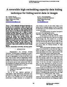
Reversible Date Hiding Using Histogram Sorting and Integer Wavelet Transform S. Yousefil, H. R. Rabiee2, E. Yousefi3, M. Ghanbari4, Fellow, IEEE
12S. Yousefi, H. R. Rabiee, Iran Telecommunication Research Center (ITRC), Tehran, Iran, Digital Media Lab (DML), Sharif University of Technology, Tehran, Iran, e-mails: syousefygyahoo.com, rabieegsharif.edu
3E. Yousefi, Computer Engineering Department, Kerman University, Kerman, Iran, e-mail: ebyousefigyahoo.com 4M. Ghanbari, Electronic Systems Engineering Department, Essex University, Yokohama, UK, e-mail: ghan gessex. ac. uk load. Shi et. Al. in [9, 10] proposed two algorithms based on integer wavelet transform. The compression of the bitplane and threshold embedding in the integer wavelet domain are the bases of these two algorithms respectively. The threshold embedding in an integer wavelet transform lets him to embed high volume of data. A complete survey of data hiding fundamentals and algorithms can be found in [8]. The rest of this paper is organized as follows. In section 2 we explain the wavelet decomposition and overflow/underflow condition prevention. Section 3 introduces our data hiding algorithm. In section 4 the proposed data retrieving and image recovery algorithm is outlined. Section 5 describes the proposed systems for data embedding and data retrieving and image recovery. Finally, sections 6 and 7 present the experimental results and concluding re-
Abstract- This paper presents a lossless data hiding method using integer wavelet transform. The modification of small coefficients of the high frequency subbands are used to embed data. We use the histogram modification to prepare enough space for data hiding. Data embedding is done by processing these selected coefficients of the modified subband histograms. We show that we can embed high capacity of data by applying multi-level integer wavelet decomposition and histogram modification. Experimental results show that our method outperforms the prior arts in terms of a larger payload.
I. INTRODUCTION
Digital data hiding can hide secret information into multimedia for secure communication. This area of research has recently found many applications in content archiving, content authentication, copyright protection, metadata insertion, broadcast monitoring, tamper detection, data security, digital fingerprinting, etc. Data hiding results in distortion of the original multimedia. For some applications it is not required to recover the original data (mark) or the original image. Therefore, most of the data hiding algorithms in the literature are not lossless and reversible. This results in a permanent distortion of the original image or hidden data. In other applications people do care about the cover media and hidden data. That is, the hidden data and original multimedia should be retrievable. So for this type of applications the hidden data and original media recovery is vital. Law enforcement and medical applications are a few samples. In the popularly used least significant bit-plane (LSB) embedding method, the bits in the LSB are replaced according to the data to be embedded and the bit-replacement is not memorized [1]. Consequently, the LSB method is not reversible. Other spatial domain methods in [2,3] or utilized spread-spectrum watermarking techniques in the DCT domain [4] or in the wavelet domain [5] are also not reversible methods. We propose a lossless and reversible algorithm for high capacity data hiding in the integer wavelet transform domain. The slight modification of the wavelet coefficients let us to do the reverse action for data recovery and reversible algorithm. At the same time the coefficient grouping in our method leads to efficient data embedding and hence leads to high data capacity insertion at high qualities. The proposed algorithms in [6,7,9] are reversible. Tian in [12] proposed a reversible data hiding algorithms by using the difference of expansion technique. This method is one of the efficient methods of insertion of large data pay-
1-4244-0470-3/07/$20.00 ©2007 IEEE
marks, respectively.
II. WAVELET DECOMPOSITION
We use the coefficients obtained by one, two or multi level integer wavelet decomposition of the original image for data embedding. To exploit frequency masking effect, the high frequency subbands of Integer Wavelet Transform (IWT), UL, LH and HH are used. After embedding data into some high frequency IWT coefficients, it is possible that after inverse wavelet transform, the grayscale values of some pixels in the marked image may exceed the upper bound (255 for an eight-bit grayscale image) and/or the lower bound (0 for an eight-bit grayscale image). This phenomenon is called overflow/underflow , that needs to be prevented [10].. It can be done by inspection of, if the recovered image is the same as the original one, the overflow/underflow problem is not occurred else the histogram preprocessing is applied to prevent this phenomenon. The histogram overflow/underflow information is saved to be used in the other stages of data hiding algorithm as the side information. III. DATA HIDING
Our data embedding method has three main steps: 1. Coefficient selection: In the coefficient selection step first we obtain the histograms of the three high frequency IWT subbands of the original image. Then, for each subband, we select n top histogram points (IWT coefficients) and setting them in a group. Now we have three groups of most top histogram points of subbanda.
487
2007 Inaugural IEEE International Conference on Digital Ecosystems and Technologies (IEEE DEST 2007)
As an example, we show this procedure on Lena image. Figs. l(a), l(b) and l(c) show main parts of the histogram of HL, LH and HH subbands respectively. Table 1 shows the selected coefficients of each subband in a group. In this example n=8 top points of each histogram are selected. These coefficients are used for data embedding in the next stages. 2. Histogram modification: In this step, we modify each IWT subband histogram based on the points obtained in the previous step. We divide the coefficients of each group into positive and negative coefficients. For each positive coefficient we up shift the related range of the histogram by "1" unit. This is equivalent to increasing by 1 the pixels greater than that coefficient. For each negative coefficient we down shift the range of histogram by " 1 " unit. This is equivalent to decreasing by 1 the pixels smaller than that coefficient. The histogram modification process aims at making zero points beside each coefficient of each group in its histogram. Figs. 2(a), 2(b) and 2(c) show the histograms of modified subbands of Lena image. These leave spaces besides the new coefficients from new groups. The new groups of subbands are shown in table 2. 3. Data embedding: The data is embedded by using the modified subbands obtained in the previous step. We scan each modified subband, once a member of the new group coefficient is met, if the to-be embedded bit is "1", the coefficient is increased by 1. Otherwise, the coefficient value is kept intact.
10000 _
I
5000 _
.
-10-9 -8 -7 -6 -5 -4 -3 -2 -1
0 1 (a)
10000 _ .
5000 _ 0
I
t
I
T
I
-10-9 -8 -7 -6 -5 -4 -3 -2 -1
I I I
2
3
4
5
I 6
7
7
0
1
2
3
4
5
6
0
1
2
3
1
5
6
(b)
I 8
9
10
8
9
10
8
9
10
I
: 10000
5000 _
l
I] -10 -9 -8 -7 -6 -5 -4 -3 -2 -1
(c)
4
IT
7
Fig. 2. IWT subbands after histogram modification step. (a) New LH histogram. (b) New HL histogram. (c) New HH histogram
LH Subband HL Subband LH New LH New HL New HL New
Subgroup 1
points
O
2 -2 4 -4 6 -6 8
Subgroup2 points
Subgroup 1 points
Subgroup2 points
1
0 2 -2 4 -4 6 -6 8
1 3 5 7 -1 -3 -5
3 5 7 -1 -3 -5
HH Subband HH HH New New
Subgroup 1 points 0 2 -2 4 -4 6 -6 -8
Subgroup2 points 1 3 5 -1 -3 -5 -7
10000 _
5000 _
T T I I I -10 -9 -8 -7 -6 -5 -4 -3 -2 -1 ,\ u _
10000
-
I
0
(a)
1
2
I 3
4
5
6
7
Table2. New IWT subband groups obtained after histogram modification step
I
I
8
9 10
IV. DATA RETRIEVING AND IMAGE RECOVERY
_
5000 _
T
o
I I I I
-10 -9 -8 -7 -6 -5 -4 -3 -2 -1
0
1
2
0
1
2
(b)
I I II.
3
4
5
,
6
7
8
9 10
7
8
9
For retrieving the embedded data we perform the following main steps: 1. The IWT is applied on the stego image. The side information is extracted from the IWT coefficients. 2. The UL, LH and HH subbands are scanned respectively. For each subband, once a pixel value of subgroupl is met, the "0" is retrieved. If a pixel value of subgroup2 is met, the "1" is retrieved. In this way, the embedded data is retrieved. 3. For recovering the original image, each subband is scanned separately. For each subband, once a pixel value of subgroup2 is met, that pixel is subtracted by 1. This is equivalent to histogram inverse modification. 4. Now we rescan each subband and perform the following operation on each subband pixel:
: 10000
5000 _
T T
ll
I
T T o -10 -9 -8 -7 -6 -5 -4 -3 -2 -1
(b)
III T 3
4
5
6
T
10
Fig. 1 Main parts of IWT subband histograms. (a) LH histogram. (b) HL histogram. (c) HH histogram
LH Subband LH Num-
Group points 0 1 -1 2 -2 3 -3 4
ber of Pixels 9760 8572 8097 6795 5712 4665 3882 3054
HL Subband HL Num-
Group points 0 1 -1 2 -2 3 -3 4
ber of Pixels 7971 7755 6893 6430 5422 4602 3866 3276
HH Subband HH Num-
Group points 0 1 -1 2 -2 3 -3 -4
ber of Pixels 8352 7350 7256 6113 6029 4585 4556 3316
Sx/2 (x-1)/2 x-nl x+n2
Tablel. IWT subband groups obtained by selecting each histogram top coefficients
1-4244-0470-3/07/$20.00 ©2007 IEEE
488
if x cSubgroupl if x Subgroup2 if X>OAxX {SubgrouplvSubgroup2} if X