Hindawi Publishing Corporation International Journal of Biomedical Imaging Volume 2016, Article ID 5054912, 25 pages http://dx.doi.org/10.1155/2016/5054912
Review Article Recent Advances in Microwave Imaging for Breast Cancer Detection Sollip Kwon and Seungjun Lee Department of Electronics Engineering, Ewha Womans University, Seoul, Republic of Korea Correspondence should be addressed to Seungjun Lee;
[email protected] Received 23 May 2016; Revised 2 September 2016; Accepted 27 October 2016 Academic Editor: Tushar K. Bera Copyright © 2016 S. Kwon and S. Lee. This is an open access article distributed under the Creative Commons Attribution License, which permits unrestricted use, distribution, and reproduction in any medium, provided the original work is properly cited. Breast cancer is a disease that occurs most often in female cancer patients. Early detection can significantly reduce the mortality rate. Microwave breast imaging, which is noninvasive and harmless to human, offers a promising alternative method to mammography. This paper presents a review of recent advances in microwave imaging for breast cancer detection. We conclude by introducing new research on a microwave imaging system with time-domain measurement that achieves short measurement time and low system cost. In the time-domain measurement system, scan time would take less than 1 sec, and it does not require very expensive equipment such as VNA.
1. Introduction Breast cancer is the most commonly diagnosed cancer in women and has the highest incidence of cancer in women. In 2012, it reached 25.2% of women worldwide. The number of patients who were diagnosed with breast cancer was about 1.7 million worldwide. According to the American Cancer Society, about 246,660 women and 2,600 men will be diagnosed with invasive breast cancer in 2016 in the United States [1]. However, if breast cancer is detected early enough, the five-year survival rate is over 90% [1, 2]. Thus, regular checkups and early detection of breast cancer are crucial. Current techniques for breast imaging are X-ray mammography, ultrasound, MRI, and positron emission tomography (PET). X-ray mammography uses low-energy X-rays to create images of the breast. It is commonly used for early breast cancer diagnosis. However, it has a number of shortcomings. Several published reports discuss that it risks exposure to radiation [3–6]. The number of women in their 40s experiencing harm from starting regular screening mammography is larger than for older women. The results of mammography revealed 1,212 of 10,000 women screened turn out to be false positives in their 40s. Harmful effects of mammography include overtreatment, unnecessary, and sometimes invasive follow-up testing and psychological harm
associated with false positive test results. Further, X-ray mammography needs compression of the breast to lie as flat as possible during the examination (Figure 1), which causes patient pain. It is difficult to distinguish tumors in dense breast mammogram images [1, 6], because both dense tissue and cancer appear white in the mammogram image, unlike fatty tissue that appears black. In Figure 2, a small tumor is conspicuous in a fatty breast; on the other hand, dense breast tissue in a heterogeneously dense breast obscures a 4 cm tumor. Other breast screening methods are adjuncts to mammography. Ultrasound uses sound waves to see internal body structure. Its frequencies are higher than 20 kHz. A transducer placed on the skin sends ultrasound pulses into the body and detects the echoes from inside the body, which are used to make ultrasound images. This is a painless method that is safe from radiation exposure. However, ultrasound has low resolution and does not distinguish between malignant and benign. Additionally, ultrasound is mostly used as a secondary technique, after a mammogram result shows a suspected mass. MRI uses radio waves and strong magnetic fields to make images of the inside body. This method utilizes the amount of absorption energy of different type of tissues. When used with soft tissue like breast, contrast liquid is
2
International Journal of Biomedical Imaging
Figure 1: Mammogram examination [7].
(a)
(b)
Figure 2: Mammogram images of a fatty breast and a heterogeneously dense breast [8]: (a) fatty breast with a small cancer (arrow), (b) heterogeneously dense breast with a 4 cm cancer (arrows) that is hidden by the dense breast tissue and notable metastatic node left of axilla (curved arrow).
injected to provide better images. MRI is typically used for further evaluation of questionable findings. Moreover, MRI is used for screening evaluation before surgical approach, for example, breast-conserving lumpectomy to mastectomy. However, MRI screening costs are high. Thus, this is barely suitable as an early detection screening method. PET is an imaging technique that observes how an injection mixture of radioactive materials with glucose or glycoprotein is used and synthesized in the human body. The cancer cells consume nutrients, because those grow much faster than normal cells. When cancer cells consume nutrients, positrons are ejected. PET makes an image by detecting these positrons. Unlike X-ray, CT, and MRI, PET
can diagnose cancer in the very early stages, because PET detects the movement of molecules in early disease cells. However, it has low resolution. Such limitations of existing breast diagnostic imaging methods motivate the research to develop alternative imaging methods. Microwave imaging has been researched as an alternative to X-ray mammography, because of its harmlessness to humans [34–37]. Microwave imaging uses the scattering wave or reflected wave that arises from the contrast in dielectric properties between normal and malignant breast tissues. In this paper, we review microwave imaging methods to detect breast cancer. First, we review studies of breast tissue properties in the microwave region. Microwave breast
International Journal of Biomedical Imaging
3
103
Malignant Dielectric constant
102
101 Normal
Conductivity (S/m)
100
Malignant
10−1 Normal
10−2 107
108
109 Frequency (Hz)
Debye equation Joines et al.
1010
Chaudhary et al. Surowiec et al.
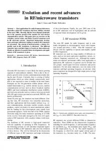
Figure 3: Dielectric properties data for normal and malignant breast tissue at radio and microwave frequencies and single-pole Debye curve fits of measured baseline [9].
imaging could be possible due to the difference in dielectric properties between malignant tissue and normal breast tissue. The following section reviews the results of microwave imaging methods so far. In addition, we introduce our studies of a newly proposed CMOS chip-based time-domain microwave imaging system.
2. Breast Tissue Properties in the Microwave Region Several groups have studied breast dielectric properties, and research results have already been published [11–13, 38, 39]. The dielectric properties of malignant and normal breast tissues show large differences; and these have been demonstrated by Joines et al. 1980, 1994; Chaudhary et al. 1984; and Surowiec et al. 1988. Figure 3 shows the dielectric properties of malignant and normal breast tissues from earlier studies. According to Chaudhary et al. 1984, malignant breast tissues at 1∼2 GHz are 3∼5 times greater than normal breast tissues. The data was obtained from 15 patients. Joines et al. 1994 showed difference between malignant and normal breast tissues at 900 MHz of 200∼500%, judging from 12 measurements of each normal and malignant breast tissue. The dielectric properties of malignant breast tissues are approximately ten times as large as normal breast tissues (Figure 3). This is because malignant tissues contain much water and are more active than normal [40, 41].
However, those earlier studies were small-scale studies. Later, a collaborative research team from the University of Wisconsin and the University of Calgary in 2007 reported a large-scale study of the ultra-wideband microwave dielectric properties of normal breast tissue obtained from reduction surgeries and a large-scale study of the ultra-wideband microwave dielectric properties of normal, benign, and malignant breast tissues [10, 15]. The first study gained tissues from reduction surgeries. The total number of patients was 93, and the total number of measurements was 488. In the latter study, the tissues were collected from cancer surgeries. The total number of patients involved in the study was 196, and the total number of samples was 319. The study measured dielectric constant data in the 0.5∼20 GHz frequency range and found that while malignant tissues were ten times larger than adipose-dominated tissues, the difference between malignant and normal glandular or fibroconnective tissues was no more than about 10%. Dielectric properties of normal tissues span a very large range, from 0–30% adipose tissues to 85–100% adipose tissues. Figure 4 depicts the dielectric properties of 85–100% adipose tissues as solid lines, 0–30% as dash-dot lines and 31–84% adipose tissues as dashed lines. Their dissertation work compared dielectric properties with previous studies. Figure 5(a) shows the dielectric properties of malignant tissue were similar to the results of previous works, unlike the dielectric properties of normal breast tissues in Figure 5(b).
4
International Journal of Biomedical Imaging 25
60
Effective conductivity (S/m)
Dielectric constant
50 40 30 20
20
15
10
5
10
5
10 Frequency (GHz)
15
20
0
5
10 Frequency (GHz)
15
20
Figure 4: Median dielectric properties of normal breast tissue in three groups categorized by the amount of adipose, from the research team of Wisconsin University and Calgary University. Dash-dot line: group 1 (0–30% adipose), dashed line: group 2 (31–84% adipose), and solid line: group 3 (85–100% adipose) [10].
Whereas initial experiments found the differences of dielectric properties between normal breast tissue and malignant tissue to be close to 10 times, large-scale experiments found that the differences were much smaller. Nevertheless, microwave imaging is still used to distinguish breast cancer [42–44]. Besides, breast cancer classification research in microwave imaging technique has been studied in the National University of Ireland [45–52]. The research of University of Wisconsin and University of Calgary [10, 15] was conducted at the ex vivo states. Dartmouth College published the correlation of in vivo and ex vivo tissue dielectric-𝑐 properties which were measured during mastectomy procedure in the operating room (in vivo) and after resection in the same location immediately from six women [16]. The research was carried out to validate the range of properties obtained from the restored images image. Overall, the properties between ex vivo and in vivo are similar, but the properties obtained ex vivo decrease when compared the properties measured in vivo (Figure 6). In addition, the research teams from University Calgary and University Wisconsin have been studying dielectric properties estimation using measurement system [53–57].
3. Microwave Breast Imaging Imaging techniques using electromagnetic waves have been used in specific fields, such as the nondestructive test of structures and detection of hidden objects [58]. Recently, with the technological development of algorithms, computation techniques, and hardware, many studies are being conducted to apply electromagnetic wave imaging technology to human diagnosis [17, 59, 60]. Microwave imaging is a promising new method for earlystage breast cancer detection. This is based on the contrast of electric parameters between the tumor and the normal breast tissue within the microwave spectrum. The method reconstructs the breast image from the received signals that
are scattered and reflected within the breast. While the resolution becomes higher as the frequency increases, tissue loss increases. Thus, it is difficult to obtain a clear image, so a limit of upper frequency of the band is needed for acceptable penetration into the tissue. An ultra-wideband signal is appropriate for these conditions. Since the penetration loss of healthy fat tissue is less than 4 dB/cm with microwave signal which is centered at 6 GHz, it is possible to reach low power signal to an antenna on the other side of an object. The specific absorption rate (SAR) is normally used when setting the safety standards for the maximum allowed exposure to the human body. SAR means the amount of power to be absorbed in the tissue per volume. Standard C95.1-1999 states that, in the case of devices operating at 100 kHz to 6 GHz, it should not exceed a maximum 1.6 W/kg for human tissue of the average 1 g [61]. As a guide, compared to a mobile phone using the same frequency band, microwave breast cancer imaging method should be free from health hazardous exposure to the patient, because of suffering less exposure than from a mobile phone. From the technical point of view, microwave breast cancer imaging method may detect a small size tumor and also has the advantage of low cost. In addition, microwave imaging can obtain an image quickly compared to other imaging methods [17]. There are two approaches to the microwave imaging method: microwave tomography and radar-based. Both approaches use the scattering of microwave signals. The systems transmit the microwave signals into the breast and then measure scattering signals reflected from the tumor. 3.1. Microwave Tomography. Microwave tomography has been studied by several research groups [18–20, 62–85]. Prof. Paulsen and Prof. Meaney from Dartmouth College in the United States are one of the representative research groups. They have studied microwave tomography breast imaging since 1990s [86–89]. They proposed an iterative
5
Effective conductivity (S/m)
Dielectric constant
International Journal of Biomedical Imaging
102 ∗
∗ ∗ ∗ ∗∗∗∗∗
101 10
7
10
8
9
10 Frequency (Hz)
10
101
100
∗
10−1 107
10
108
∗∗∗ ∗ ∗ ∗ ∗∗
109 Frequency (Hz)
1010
(a)
102
∗
Effective conductivity (S/m)
Dielectric constant
101
∗ ∗ ∗∗ ∗∗∗ ∗
101
100
10 100
107
108
109 Frequency (Hz)
∗
−1
107
1010
108
∗ ∗∗ ∗ ∗ ∗ ∗∗
109 Frequency (Hz)
1010
(b)
Figure 5: Comparison of malignant tissues and normal breast tissues dielectric properties of previous studies and from the Wisconsin University and Calgary University research team. (a) Malignant tissues properties; (b) normal breast tissues properties. Lines: median dielectric properties of the cancer samples from Wisconsin University and Calgary University research team (dash-dotline: group 1, 0–30% adipose, dashed line: group 2, 31–84% adipose, solid line: group 3, 85–100% adipose). Symbols: malignant breast tissue dielectric properties data published previously (∘, Chaudhary et al. [11]; Δ, Surowiec et al. [12]; ∗, Joines et al. [13]). Vertical arrows: range of data reported by Campbell and Land [14] at 3.2 GHz for malignant tissues [10, 15].
reconstruction algorithm that obtains dielectric properties in a 2D lossy medium in 1995. The goal of microwave tomography is to recover the profile using the inverse problem of the dielectric properties of the breast. Microwave tomography uses an inverse scattering method to get a breast diagnostic image. Inverse scattering uses scattering signals including diffraction from objects. It creates a map of permittivity and conductivity through inversion of those signals. However, the inverse problem takes much time, because the calculation process is complicated. Also, a nonlinear inverse scattering problem must be solved, and iterative image reconstruction algorithms are usually required to obtain a solution. In general, these ill-posed inverse scattering approaches suffer from nonuniqueness and
require regularization in order to achieve convergence to a meaningful solution [66, 90]. The Dartmouth group has developed a clinical prototype for active microwave imaging of the breast for the first time [18]. They developed a 32-channel data acquisition system operating at frequency range 500 MHz to 3 GHz [87] to obtain data from a clinical prototype exam. The clinical prototype illuminates the breast with 16 monopole antennas that operate in the 300 MHz to 1 GHz frequency range. The clinical exam was conducted with 5 women, and the total acquisition time was 10–15 minutes per breast. The system measured data at seven different array heights. The data were obtained from seven different array heights for seven different frequencies at each array position. Figure 7
6
International Journal of Biomedical Imaging In vivo/ex vivo conductivity spectra
In vivo/ex vivo relative permittivity spectra
10000000
0.6
Relative permittivity
Conductivity (S/m)
0.7 0.5 0.4 0.3 0.2 0.1
1000000 100000 10000 1000 100
0
10 0.1
1
10
100
0.1
1 10 Frequency (kHz)
Frequency (kHz) In vivo, tumor Ex vivo, IDCa/DCIS
100
In vivo, tumor Ex vivo, IDCa/DCIS (a)
In vivo/ex vivo conductivity spectra
12
Relative permittivity
Conductivity (S/m)
14 10 8 6 4 2 0 0
1
2
3
4
5
6
7
8
9
Frequency (GHz) In vivo, tumor Ex vivo, IDCa/DCIS
In vivo/ex vivo relative permittivity spectra
100 90 80 70 60 50 40 30 20 10 0
2
4 6 Frequency (GHz)
8
10
In vivo, tumor Ex vivo, IDCa/DCIS (b)
Figure 6: In vivo versus ex vivo dielectric spectra (electrical impedance spectroscopy (EIS) (a) and microwave impedance spectroscopy (MIS) (b)). Multiple spectra recorded for EIS are shown, while the average MIS spectrum is illustrated [16].
Figure 7: The microwave breast imaging system at Dartmouth College [17].
shows the tomographic microwave breast imaging system at Dartmouth College. Figure 8 shows the woman being screened using the clinical prototype and Figure 9 shows the resultant images. They have also developed a prototype of breast cancer detection system based on 3D FEM method microwave tomography [19, 20]. Figure 10 shows the prototype with computer-controlled arrays. They presented the first clinical 3D microwave tomographic images of the breast using the
prototype [20]. The study achieved improvements of both hardware and software aspects and achieved data acquisition time of less than 2 minutes by development of special hardware. The image processing time was within 20 minutes. This is very fast compared to ten of hours or even days for a single 3D microwave tomographic image [91]. Figure 11 shows the 2D and 3D tomographic permittivity images [20]. They used the 3D microwave breast imaging system for monitoring treatment response during neoadjuvant
International Journal of Biomedical Imaging
7
(a)
(b)
Figure 8: Photographs of a microwave exam with patient in Dartmouth College. (a) Close-up view, and (b) the breast in position within the center of the antenna array [18].
900 MHz patient 2 left breast Position 1
Position 2
Position 3 90 81 72 63 54 45 36 27 18 9 0
2.8 2.52 2.24 1.96 1.68 1.4 1.12 0.84 0.56 0.28 0
(a)
900 MHz patient 2 right breast Position 1
Position 2
Position 3 90 81 72 63 54 45 36 27 18 9 0
2.8 2.52 2.24 1.96 1.68 1.4 1.12 0.84 0.56 0.28 0
(b)
Figure 9: Recovered 900 MHz relative permittivity and conductivity images from patient (a) left breast and (b) right breast [18].
8
International Journal of Biomedical Imaging
Figure 10: The 3D microwave tomographic breast cancer imaging system of Dartmouth College [19].
35
35
30
30
25
25
20
20
15
15
10
10
5
5
0
0
(a)
(b)
Figure 11: Microwave tomographic permittivity images at 1300 MHz from Dartmouth College; upper: right breast; lower: left breast. (a) 2D images and (b) 3D images [20].
chemotherapy [20, 92]. Tomographic images were obtained eight times from eight patients undergoing neoadjuvant chemotherapy during the course of treatment [92]. The results of the study indicate that the conductivity in locally advanced breast cancer matched well with overall neoadjuvant therapy treatment response [92]. In Korea, Electronics and Telecommunications Research Institute (ETRI) started research of the breast cancer diagnostic technology of microwave tomography in 2007. ETRI MT breast cancer diagnostic techniques have been studied using a microwave signal in the 500 MHz to 3 GHz range [21, 78, 93]. Figure 12 shows a flow chart of the ETRI iterative reconstruction algorithm [21]. Figure 13 shows the microwave tomographic breast imaging system developed by ETRI. Experimental ETRI MT system consists of cylindrical breast phantom and cylindrical tumor phantoms (Figure 13). The five thin-wall plastic pipes displayed here are filled with the liquid of complex permittivity similar to a real tumor. Figure 14(a) shows reconstructed images of a breast without a
tumor, and Figures 14(b) and 14(c) present images of a single cylindrical tumor at the central and shifted positions [21]. King’s College in London has been developing antenna for microwave tomography [84, 94], and they applied an adaptive multithreshold iterative shrinkage algorithm to the linear inversion at each iteration of the Distorted Born Iterative Method (DBIM) [95]. Some groups are researching on reducing high computational demands due to a number of iteration and discretization of the object image for accuracy. Xu et al. in University of Manitoba proposed an iterative process that involves two algorithms: Finite-Difference Time-Domain (FDTD) and Genetic Algorithm (GA). They developed a parallel algorithm for microwave tomography on CPU-based homogeneous multicore distributed memory machines and the Cell BE processor [68, 69, 76]. The research group in National University of Ireland Galway in Ireland presented a novel parallelization strategy to accelerate microwave tomography [85]. IREA, National Research Council of Italy, has developed diagnostic and therapeutic
International Journal of Biomedical Imaging
9
Start reconstruction
Set property distribution to initial estimate
Interpolation Evaluate forward
Update property
field solution
Magnitude phase
Extract computed field values
Ecal − Emea
Calculate field misfit error
Compare with stopping criteria
Continue interpolation
distribution
Spatial filter
Solve for parameter update
Gauss-Newton method
Determine regularization parameter
regularization
Tikhonov
Compute Jacobian
Stop End construction
Figure 12: Flow chart of the ETRI reconstruction algorithm [21].
strategies based on the use of electromagnetic fields at microwave frequencies for some years. They have researched magnetic nanoparticles (MNP) enhanced microwave imaging which is able to reduce the rate of false positive and negative [22, 96–98]. Figure 15 shows the experimental setup for the MNP enhanced MWI technique which IREA developed. Microwave ablation monitoring via microwave tomography also has been researched in IREA [99]. In addition, the research has been progressed in therapeutic aspects with microwave ablation at IREA and University of WisconsinMadison [100–102]. 3.2. Radar-Based Microwave Imaging. Microwave radar imaging reconstructs the image using the reflected wave from objects. It uses the reflection that arises due to difference in the electrical dielectric properties of normal and malignant breast tissues, when microwaves transmit the internal breast with tumor. This approach, which was first developed as a military ground-penetrating application, is applied to the human body. It was designed in the late 1990s by Hagness in Wisconsin University, and Benjamin in
Bristol University [9, 24, 103–106]. Researchers in National University of Ireland Galway, Tianjin University in China, and Hiroshima University are also working on this subject [107–123]. Recently, Goethe University of Frankfurt and University of Bristol have been developed experimental phantom based on 3D printing technology that was one step close to the development of standard breast phantoms [124]. A 3D image of the received signals through the breast is obtained by focusing algorithms. Before applying the focusing algorithm, preprocessing is performed to obtain a tumor response. Preprocessing may contain the extracting tumor response, compensation tissue losses, or radial spread. Among the preprocessing, extracting tumor response must be conducted, because the received signal includes not only the tumor response, but also unwanted signals such as antenna coupling, directly received signals from the transmit antenna, and reflections from the skin. Existing techniques to extract tumor response are differential calibration [37] and array rotation calibration [36]. Differential calibration techniques use a reference signal obtained from a scan of a healthy breast [37]. However, it
10
International Journal of Biomedical Imaging
10
9 Head
8
11
7
12
6 Imaging zone
13
5
R
14
4 3
15 16
Feet 1
2
14 cm 15 cm
Figure 13: ETRI microwave tomography system [21].
is hard to use when previous knowledge of the cancer-free breast does not exist. In the array rotation calibration method, two sets of measured data are received from a physically rotating antenna array, in which unwanted signals are almost the same [36]. These two methods measure two sets of the signals by multiple measurements. A calibrated signal is obtained by subtracting one of the two sets of the signals from the other. We have proposed a new calibration method called “inplace calibration” to extract a tumor response [125, 126]. The received signal and the reference signal are measured at the same time. In-place calibration eliminates unwanted signals using dual receivers, Rx1 and Rx1 , located an equal distance from the transmitter Tx in Figure 16. Antenna coupling and skin reflection received by the two antennae occur at an identical time, unlike tumor responses that transpire in a
different time due to a slight delay. Thus, the calibrated signal of a tumor response can be obtained by subtracting one received signal from the other. In-place calibration reduces the time of measurement. In addition, measurement errors that occur due to environmental changes during calibration, such as a mechanical error during antenna array rotation or an accidental error due to the unexpected movement of the patient, are minimized. Extra hardware for calibration like highly precise motor for rotation is not required. We assumed that the breast shape is hemispherical while a real breast is not exactly rotational symmetric. Various breast shapes other than hemispherical may hinder the in-place calibration method. A possible solution for this is to provide different sizes of hemispherical measurement bowls such that a breast can tightly fit into the bowl during measurement. In addition,
International Journal of Biomedical Imaging
(a)
11
(b)
(c)
Figure 14: Reconstructed images of cylindrical tumor (10 mm diameter pipe) inside bath liquid at ETRI. (a) Breast without tumor (b) with tumor at center and (c) with tumor 30 mm right of center [21].
Rx1
Tx
+/−
MNP Rx1
Breast phantom
Figure 15: Experimental setup of IREA, National Research Council of Italy for MNP enhanced microwave imaging [22].
there might be mismatches between two antennae. It can be easily compensated once the characteristics of the antennae are obtained [126]. Focusing algorithms that are used for image reconstruction in radar-based microwave imaging include the delay and sum (DAS) [36, 127–129], microwave imaging via space-time (MIST) [108, 128, 130], robust weighted Capon beamforming (RWCB) [131], multistatic adaptive microwave imaging (MAMI) [36, 110], and generalized likelihood ratio test (GLRT) [109, 132]. DAS is a simple and robust method. Also, the computation time is short. The signals are shifted by time 𝑇𝑖 calculated from their respective location relative to the antennae, to
Figure 16: In-place calibration with dual receivers.
restore the image. The focal point is assumed to be 𝑝 = (𝑥, 𝑦, 𝑧). The time delay 𝑇𝑚𝑛 is assumed as the time delay of the signal from transmitting at the 𝑚th antenna to receiving at the 𝑛th antenna. The time delay 𝑇𝑚𝑛 at the focal point p can be expressed as 𝑇𝑚𝑛 (𝑝) =
1 2 2 2 1/2 {[(𝑥𝑚 − 𝑥) + (𝑦𝑚 − 𝑦) + (𝑧𝑚 − 𝑧) ] V 2
2
2 1/2
+ [(𝑥𝑛 − 𝑥) + (𝑦𝑛 − 𝑦) + (𝑧𝑛 − 𝑧) ]
(1)
}.
If the number of antennae is 𝑁, the number of signals used by the focusing algorithm is 𝑀 = 𝑁 × (𝑁 − 1)/2. The time delay applies the received signal rs𝑖 differently for each transmit antenna and receive antenna. The intensity
12
International Journal of Biomedical Imaging FRCB
RCB
50
Y (mm)
Y (mm)
50
100
100
150
150
50
100
50
150
100
150
100
150
Z (mm)
Z (mm) MAMI
FMAMI
50 Y (mm)
Y (mm)
50
100
100
150 150
50
100
150
Z (mm)
50 Z (mm)
(a)
(b)
Figure 17: 2D slice of reconstructed images from National University of Ireland Galway (a) without prefiltering and (b) with prefiltering [23].
of a reconstruction image is calculated by moving the focal point from one position to another within the breast. The integration window 𝜏 is determined by the input pulse width. Normally, 𝜏 uses 50 percent longer than the input pulse width, due to the antenna effects and dispersion [133]. The intensity 𝐼𝑝 of the restored image at the given focal point can be expressed as 𝐼𝑝 (𝑥, 𝑦, 𝑧) 𝜏
𝑀
0
𝑖=1
2
= ∫ (∑𝑤𝑖 (𝑥, 𝑦, 𝑧) ⋅ rs𝑖 (𝑡 − 𝑇𝑖 (𝑥, 𝑦, 𝑧))) 𝑑𝑡,
(2)
where 𝑤𝑖 is the location-dependent weight calculated during preprocessing, rs𝑖 is the received signal, and 𝑇𝑖 is the time delay. Microwave imaging via space-time (MIST) beamforming uses finite impulse response (FIR) filters to compensate for the frequency-dependent time delay, such as dispersion
and fractional time delay. The microwave image is formed by summing the filtered signals. Microwave breast cancer imaging uses a generalized likelihood ratio test (GLRT), which is a hypothesis testing problem for each voxel, with the null hypothesis representing the tumor-free case. Reference [109] shows the image formation equations. However, most of those methods have suffered from performance degradation used with dense breast. Thus, in the National University of Ireland Galway they used preprocessing filter to compensate the path-dependent attenuation and phase effects. Consequently, they achieved more clear images (Figure 17) [23]. In addition, they investigated the focal quality metrics to estimate average dielectric properties to enhance tumor detection [51]. University of Bristol also presented a timedomain wideband adaptive beamforming to reduce clutter [134]. The approach uses an adapted equalization filter that adapts a calculated estimation of averaging dielectric properties of the breast.
International Journal of Biomedical Imaging
13
Switch matrix VNA C
GPIB (data, instrument control)
(16 feeds)
A PC
B
USB (switch control)
Figure 18: Radar-based microwave imaging system schematic with frequency domain measurement for breast cancer detection at Bristol University [24].
Figure 19: Clinical test with microwave radar-based system at Bristol University [25].
3.2.1. Frequency Domain Measurement. Radar-based microwave imaging can be done through two approaches: frequency domain analysis and time-domain analysis. There have been several microwave systems reported in the literature, most of which are based on frequency domain analysis [24, 26, 28, 36, 135]. However, frequency domain analysis
requires equipment, such as a costly vector network analyzer (VNA). The process takes a lot of time, because it measures 𝑠parameters by sweeping frequencies; and measurement time is critical in medical imaging: patient movement during a scan may generate artifacts. University of Bristol team performed experimental and clinical study using UWB microwave radar imaging method for the first time [25]. Figure 18 shows a schematic of the multistatic radar-based microwave breast imaging system [24]. Scattered signals are measured in the frequency domain using VNA. A switch matrix connected to the feed of the antennas changes the pair of antennae during measurement of the signals. The signals are measured, in turn, by all possible pairs of antennae that activate the transmit port and receive port. The measured signals with frequency domain are transferred to time-domain signals using an inverse FFT method. The image is reconstructed by a focusing algorithm using the time-domain signals. Figure 19 shows the microwave radarbased clinical setup for breast cancer detection with a patient. Clinical verification was performed with real breast cancer patients at the Bristol Oncology Center. Figure 20 shows that the contribution compared images obtained using X-ray mammography and the radar-based microwave system [25]. Figure 21(a) shows the system based around 31 UWB slot antennas called “MARIA” that University of Bristol team developed [42, 135]. It uses a 2 port VNA, and takes approximately 90 seconds to scan. However, 90 seconds is a long time to scan patients, and artifacts can occur due to patient movement. Subsequently, the team developed a
14
International Journal of Biomedical Imaging
−60
Max. focussed strength at (X = 27, Y = −15, Z = −12 mm)
−50 −40 −30 −20 −10 0
60
40
20
0
(a)
−20
−40
−60
1 0.9 0.8 0.7 0.6 0.5 0.4 0.3 0.2 0.1 0
(b)
Figure 20: Comparison clinical images of the radar-based microwave imaging and X-ray mammogram result at Bristol University: (a) X-ray mammogram and (b) radar-based UWB microwave system (2D slice through a plane with tumor) [25].
(a)
(b)
Figure 21: (a) 31-element prototype and (b) 60-element antenna array at Bristol University [26].
Figure 22: The completed 60-way TX/RX electromechanical switching interface at Bristol University [26].
60-element antenna array with 8 port VNA (Figure 21(b)). Figure 22 shows the electromechanical switching interface for the 60-way TX/RX. The scan time with the 60-element array achieved 10 seconds. Figure 23 shows the radar-based breast imaging system of MICRIMA which was founded in 2006 to develop and commercialize the technology of microwave radar breast imaging at the University of Bristol in the UK. The MICRIMA’s MARIA system has undergone clinical trials at the several breast cancer imaging centers in the UK and got European regulatory approval in 2015 [27]. University of Calgary have developed a tissue sensing adaptive radar (TSAR) prototype of radar-based breast imaging system (Figure 24) [28]. The patient lies face down on the table to be scanned and immerses the breast in a tank filled with immersion liquid. Their system was different from the system of Bristol University, using a monostatic method and filtering the reflection from the skin. They scanned a small group of patients using the prototype [136]. The results were positive, since several restored images exhibited responses
International Journal of Biomedical Imaging
15
Figure 23: Breast imaging system “MARIA” of MICRIMA [27].
Figure 24: TSAR prototype system in Calgary University [28].
which were similar to clinical results. They also studied 3D surfaces acquisition of the breast for radar-based microwave breast imaging [137] and investigated the impact of the breast model complexity on microwave imaging signals [138]. 3.2.2. Time-Domain Measurement. Several research groups have recently reported time-domain measurement microwave breast imaging systems [29, 31, 37, 139]. Time-domain measurement systems have the advantage of being costeffective and requiring less scan time. McGill University in Canada is a leading research group in time-domain measurement microwave imaging systems for the detection of breast cancer. Figure 25 shows the experimental system that is a multistatic radar-based microwave system with 16-element antenna array for breast cancer detection that their research team developed [29]. Figure 26 shows that the time system transmits input pulse using a pulse generator and receives the signal from antennae using an oscilloscope in real time [29, 140]. Further, the McGill University research team have performed an early clinical study of time-domain microwave radar for breast health monitoring [30, 141]. They collected a total of 342 breast scans over an eight-month period with 13 healthy volunteers for monthly scans [141]. The purpose of the study was to investigate the impact of unavoidable multiple factors of human in monthly monitoring. Figure 27 shows a scanning patient on the table with the clinical system at McGill University. In addition, they have developed wearable bra
prototype using microwaves for breast health monitoring [142, 143]. However, the system still depends on a high-precision pulse generator and very high-speed oscilloscope and may require complicated switching circuits. Additionally, a timedomain system requires a very fast sampling clock such that even a very small jitter in the sampling clock might blur the resulting images [144]. Figure 28 shows the system implementation using CMOS circuits as an alternative to high-speed pulse generator and oscilloscope proposed by Hiroshima University in Japan [31]. Figure 29 shows the measurement setup with CMOS Gaussian monocycle pulse (GMP) transmitter developed by Hiroshima University [32]. Also, Figure 30 shows a GMP equivalent time sampling circuit for confocal imaging developed by a Hiroshima University team [33]. In [34], we proposed an instantaneous microwave imaging system with time-domain measurements. The system consists of a master controller and 16 UWB transceivers. Figure 31 shows the configuration of the timedomain microwave breast imaging system that we previously presented. It consists of 16 UWB transceivers around a 3D hemisphere, with a master controller at the center. We used CMOS transceiver chips instead of a high-precision pulse generator and high-speed oscilloscope; also, a master controller performs the role of switching matrix. We used the equivalent time sampling technique to achieve a sampling rate of 28.2 Gs/s by 1.76 GHz sampling clock. A single system
16
International Journal of Biomedical Imaging
Figure 25: Antenna array at McGill University [29]. Ax Amplifier +35 dB A5 A6
8 × 1 switch
A1
A 16
.. .
.. .
A8
A9
8 × 1 switch
A7 A8
Directional coupler
SBR
A1 A2
A3
A4 A 16
A 12 A 11 A 10 A 9
A 15
2 × 1 switch
A 14 A 13
Impulse generator
Clock (25 MHz)
Clock (25 MHz)
Picoscope
Figure 26: Schematic diagram of the time-domain breast imaging system of McGill University [29].
Figure 27: Photos of clinical prototype with test table and scanning patient at McGill University [30].
clock from the master controller drives all the 16 transceivers. The transceivers transmit a UWB pulse one at a time, and the rest of them receive the signal simultaneously, such that the total scan time can be dramatically reduced to 1.32 𝜇sec at 1.76 GHz sampling clock, while a typical scan time with a frequency domain system is more than 10 seconds. As
patient movements during measurement cause artifacts in the acquired image, and a fast scan time is very critical for achieving a clear breast image. Figure 32 shows our system diagram. The master controller coordinates the operation of 16 UWB transceivers and distributes a global clock to transceivers. Also, it collects all
International Journal of Biomedical Imaging
Transmitted GMP
17
Tumor
Received GMP Amplified GMP
Power amp
Track & hold circuit
LNA
Digital signal
Reference clock
Gaussian monocycle pulse
100 MHz
A/D converter
PC/ FPGA
Sampling clock
Gaussian monocycle pulse generator
Phase locked loop 100 MHz
Transmitter circuits
100 MHz
Receiver circuits
100 MHz Reference clock
Figure 28: A Hiroshima University concept for a CMOS breast cancer detection system [31].
Pulse/pattern generator Agilent 81134A
Sampling oscilloscope Agilent 86100C
Trigger
DC power supply Agilent E3631 CLK 100 MHz
Down-pulse generator Antenna interface
Power amp
Up-pulse generator
Input
Output
Tx chip (GMP generator) Switching matrix DC power supply Agilent E3631
Breast tumor phantom
10 mm
10 mm
Figure 29: Measurement setup with CMOS-GMP transmitter of Hiroshima University [32].
18
International Journal of Biomedical Imaging
Agilent pulse pattern generator 81134A
Trigger (1/32768)
Agilent E3631A Triple output power supply
CLK
VDDPLL VBMUX VDEPLL
UF.L cable
Terminal
VBPMOS VBNMOS
SELD 3.3 V
Agilent E3620A power supply
CLR 0 V
10 M ref
EN 3.3 V
Agilent serial pulse data generator 81142A
Terminal
2 × 3 pins
DC 5214 IFN PCB
DC block
2 × 6 pins
Input GMP
Terminal
Oscilloscope Agilent MSO7104A CMOS
GS probe
VDDDIG VDE GND
4-bit digital
Output
Terminal
Terminal VREFM VREFP VDDADC
VBTHC VDDTHC
Figure 30: GMP equivalent time sampling measurement setup of Hiroshima University [33].
UWB transceiver Master controller M
UWB transceiver
Tumor
PC
Clock and data cable
(a)
(b)
Figure 31: Breast cancer imaging system with 16 UWB transceivers. (a) Configuration of 16 UWB transceivers and master controller and (b) location of 16 UWB transceivers with a 3 mm radius tumor inside [34].
International Journal of Biomedical Imaging
19
Transmitter
Start PC
LNA
ADC
UWB transceiver 01 Making control signal block
Transmitter
ADC
LNA
UWB transceiver 02
Memory
Transmitter PLL LNA
ADC
UWB transceiver 03 .. .
Master controller chip
Transmitter Clock LNA
ADC
UWB transceiver 16
Figure 32: Block diagram of time-domain breast imaging system.
received signals from transceivers and samples them using equivalent time sampling. The collected signals are delivered to a PC for image reconstruction. The time-domain measurement system suffers from a low signal to noise ratio, because high frequency RF signal attenuates rapidly within breast tissue. Thus, the signals have to be measured repeatedly and averaged to improve SNR, because SNR is proportional to the square root of the number of measurements. Figure 33 shows the restored image of 3D hemispherical breast model composed of a 2 mm thick skin, fat, and 3 mm radius tumor with 1,000 measurements when all possible noise sources are present, such as clock skew (±1% + 5 ps), clock jitter (1.6 ps), and white noise. The diameter of the breast model is 84 mm and the tumor located at 𝑥 = 70, 𝑦 = 60, and 𝑧 = 17. 16 antennae which are placed along the breast model transmit a modulated Gaussian pulse which is centered 6 GHz with pulse width 0.3 ns.
4. Conclusions Several research groups have studied microwave breast imaging systems that are noninvasive and not harmful to human as alternative early diagnostic breast cancer imaging methods.
Besides, microwave imaging system does not require the compression of breast. Unlike initial studies, a large-scale study published in 2007 found that the variation of dielectric properties of the normal breast is large. Further research such as classification is going on to solve heterogeneity in the breast. Several groups have already conducted clinical trials with patients and the results are very promising. In particular, a CMOS chip-based time-domain measurement microwave system can reduce the scan time to within 1 sec when the 1000 repeated signals are averaged with 16 antennae. In the time-domain measurement, it takes 1.32 𝜇sec as once measurement by equivalent time sampling with 1.76 GHz sampling clock. Thus, it can diminish the artifacts caused by patient movements due to long measurement time. In addition, it can be implemented at low prices, because it does not require expensive equipment like VNA, oscilloscope, and pulse generator. The prices of VNA, oscilloscope, and pulse generator are about $10,000∼100,000 while a transceiver chip is about $100. Thus, the production cost of our imaging system prototype may be less than $3,000. The development of such a microwave breast imaging system will help young women with dense breast to receive regular breast cancer screening safely.
20
International Journal of Biomedical Imaging 120
1 0.9
100 0.8 80
0.7 0.6
y
60 0.5 40
0.4 0.3
20
z
1
40
0.8
30
0.6
20 0.2 20
40
60
80
100
120
0.4
10
0.2
0.1
20
40
60
x
x
(a)
(b)
80
100
120
1
40
0.8
30
0.6
20
0.4
10
0.2 20
40
60
80
100
120
y (c)
z-axis
1
50
z
50
50 40 30 20 10 0
0.8 0.6 0.4 100
y-axi s
50
0
0
50 s x-axi
100
0.2
(d)
Figure 33: Cross-sectional images of restored breast model with 1,000 measurements, (a) 𝑥-𝑦 plane, 𝑧 = 17, (b) 𝑥-𝑧 plane, 𝑦 = 70, (c) 𝑦-𝑧 plane, 𝑥 = 60, and (d) 3D image [34].
Competing Interests The authors declare that they have no competing interests.
Acknowledgments This work was supported in part by Basic Science Research Program through the National Research Foundation of Korea (NRF) funded by the Ministry of Education, Science and Technology (no. 2-2014-2321-001-1).
References [1] A. C. Society, Cancer Facts & Figures, The Society, New York, NY, USA, 2016. [2] K. B. C. Society, Breast Cancer Facts & Figures 2014, Korean Breast Cancer Society, Seoul, South Korea, 2014. [3] L. L. Humphrey, M. Helfand, B. K. S. Chan, and S. H. Woolf, “Breast cancer screening: a summary of the evidence for the U.S. Preventive Services Task Force,” Annals of Internal Medicine, vol. 137, no. 5, pp. 347–360, 2002. [4] U. P. S. T. Force, “Screening for breast cancer: recommendations and rationale,” Annals of Internal Medicine, vol. 137, p. 344, 2002.
[5] U. P. S. T. Force, “Screening for breast cancer: US Preventive Services Task Force recommendation statement,” Annals of Internal Medicine, vol. 151, p. 716, 2009. [6] A. L. Siu, “Screening for breast cancer: U.S. Preventive services task force recommendation statement,” Annals of Internal Medicine, vol. 164, no. 4, pp. 279–296, 2016. [7] Mammogram image, http://www.cancer.org/cancer/breastcancer/detailedguide/breast-cancer-diagnosis. [8] D. R. Hooley, “Mammographic Images Showing How Cancer Looks in Each of the Breast Density Categories,” Dense Breast info, http://densebreast-info.org/faqs-for-health-professionals .aspx. [9] X. Li and S. C. Hagness, “A confocal microwave imaging algorithm for breast cancer detection,” IEEE Microwave and Wireless Components Letters, vol. 11, no. 3, pp. 130–132, 2001. [10] M. Lazebnik, L. McCartney, D. Popovic et al., “A large-scale study of the ultrawideband microwave dielectric properties of normal breast tissue obtained from reduction surgeries,” Physics in Medicine and Biology, vol. 52, no. 10, p. 2637, 2007. [11] S. S. Chaudhary, R. K. Mishra, A. Swarup, and J. M. Thomas, “Dielectric properties of normal & malignant human breast tissues at radiowave & microwave frequencies,” Indian Journal of Biochemistry and Biophysics, vol. 21, no. 1, pp. 76–79, 1984. [12] A. J. Surowiec, S. S. Stuchly, J. R. Barr, and A. Swarup, “Dielectric properties of breast carcinoma and the surrounding tissues,”
International Journal of Biomedical Imaging
[13]
[14]
[15]
[16]
[17]
[18]
[19]
[20]
[21]
[22]
[23]
[24]
[25]
[26]
IEEE Transactions on Biomedical Engineering, vol. 35, no. 4, pp. 257–263, 1988. W. T. Joines, Y. Zhang, C. Li, and R. L. Jirtle, “The measured electrical properties of normal and malignant human tissues from 50 to 900 MHz,” Medical Physics, vol. 21, no. 4, pp. 547– 550, 1994. A. M. Campbell and D. V. Land, “Dielectric properties of female human breast tissue measured in vitro at 3.2 GHz,” Physics in Medicine and Biology, vol. 37, no. 1, pp. 193–210, 1992. M. Lazebnik, D. Popovic, L. McCartney et al., “A large-scale study of the ultrawideband microwave dielectric properties of normal, benign and malignant breast tissues obtained from cancer surgeries,” Physics in Medicine and Biology, vol. 52, no. 20, pp. 6093–6115, 2007. R. J. Halter, T. Zhou, P. M. Meaney et al., “The correlation of in vivo and ex vivo tissue dielectric properties to validate electromagnetic breast imaging: initial clinical experience,” Physiological Measurement, vol. 30, no. 6, pp. S121–S136, 2009. E. C. Fear, P. M. Meaney, and M. A. Stuchly, “Microwaves for breast cancer detection?” IEEE Potentials, vol. 22, no. 1, pp. 12– 18, 2003. P. M. Meaney, M. W. Fanning, D. Li, S. P. Poplack, and K. D. Paulsen, “A clinical prototype for active microwave imaging of the breast,” IEEE Transactions on Microwave Theory and Techniques, vol. 48, no. 1, pp. 1841–1853, 2000. P. M. Meaney, M. W. Fanning, T. Zhou, A. Golnabi, S. D. Geimer, and K. D. Paulsen, “Clinical microwave breast imaging— 2D results and the evolution to 3D,” in Proceedings of the 2009 International Conference on Electromagnetics in Advanced Applications (ICEAA’09), pp. 881–884, Torino, Italy, September 2009. T. M. Grzegorczyk, P. M. Meaney, P. A. Kaufman, R. M. Diflorio-Alexander, and K. D. Paulsen, “Fast 3-D tomographic microwave imaging for breast cancer detection,” IEEE Transactions on Medical Imaging, vol. 31, no. 8, pp. 1584–1592, 2012. S.-H. Son, N. Simonov, H.-J. Kim, J.-M. Lee, and S.-I. Jeon, “Preclinical prototype development of a microwave tomography system for breast cancer detection,” ETRI Journal, vol. 32, no. 6, pp. 901–910, 2010. O. M. Bucci, G. Bellizzi, A. Borgia et al., “Experimental feasibility assessment of MNP enhanced microwave diagnostics of breast cancer,” in Proceedings of the 10th European Conference on Antennas and Propagation (EuCAP ’16), pp. 1–4, Davos, Switzerland, April 2016. A. Shahzad, M. O’Halloran, E. Jones, and M. Glavin, “A preprocessing filter for multistatic microwave breast imaging for enhanced tumour detection,” Progress In Electromagnetics Research B, no. 57, pp. 115–126, 2014. I. J. Craddock, M. Klemm, J. Leendertz, A. W. Preece, and R. Benjamin, “Development and application of a UWB radar system for breast imaging,” in Proceedings of the Loughborough Antennas and Propagation Conference (LAPC ’08), pp. 24–27, IEEE, Loughborough, UK, March 2008. M. Klemm, I. Craddock, J. Leendertz, A. Preece, and R. Benjamin, “Experimental and clinical results of breast cancer detection using UWB microwave radar,” in Proceedings of the 2008 IEEE International Symposium on Antennas and Propagation and USNC/URSI National Radio Science Meeting (APSURSI’08), pp. 1–4, San Diego, Calif, USA, July 2008. M. Klemm, D. Gibbins, J. Leendertz et al., “Development and testing of a 60-element UWB conformal array for breast cancer
21
[27] [28]
[29]
[30]
[31]
[32]
[33]
[34]
[35]
[36]
[37]
[38]
[39]
[40]
imaging,” in Proceedings of the 5th European Conference on Antennas and Propagation (EUCAP’11), pp. 3077–3079, April 2011. Micrima, http://www.micrima.com/. J. Bourqui, J. M. Sill, and E. C. Fear, “A prototype system for measuring microwave frequency reflections from the breast,” International Journal of Biomedical Imaging, vol. 2012, Article ID 851234, 12 pages, 2012. E. Porter, E. Kirshin, A. Santorelli, M. Coates, and M. Popov´ı, “Time-domain multistatic radar system for microwave breast screening,” IEEE Antennas and Wireless Propagation Letters, vol. 12, pp. 229–232, 2013. E. Porter, A. Santorelli, and M. Popovi´c, “Breast monitoring via time-domain microwave radar: early clinical trial study,” in Proceedings of the 35th Annual International Conference of the IEEE Engineering in Medicine and Biology Society (EMBC ’13), pp. 6601–6604, IEEE Engineering in Medicine and Biology Society, Osaka, Japan, 2013. T. Kikkawa, A. Toya, S. Kubota, M. Hafiz, A. Azhari, and N. Sasaki, “IR-UWB-CMOS circuits for breast cancer detection,” in Proceedings of the 6th European Conference on Antennas and Propagation (EuCAP ’12), pp. 1758–1760, IEEE, Prague, Czech Republic, March 2012. T. Sugitani, S. Kubota, M. Hafiz, A. Toya, and T. Kikkawa, “A breast cancer detection system using 198 ps Gaussian monocycle pulse CMOS transmitter and UWB antenna array,” in Proceedings of the IEEE URSI International Symposium on Electromagnetic Theory (EMTS ’13), pp. 372–375, Hiroshima, Japan, May 2013. Y. Seo, K. Sogo, A. Toya et al., “CMOS equivalent time sampling of Gaussian monocycle pulse for confocal imaging,” in Proceedings of the 10th IEEE Biomedical Circuits and Systems Conference (BioCAS’14), pp. 125–128, Lausanne, Switzerland, October 2014. S. Kwon and S. Lee, “Instantaneous microwave imaging with time-domain measurements for breast cancer detection,” Electronics Letters, vol. 49, no. 10, pp. 653–654, 2013. J. M. Sill and E. C. Fear, “Tissue sensing adaptive radar for breast cancer detection-experimental investigation of simple tumor models,” IEEE Transactions on Microwave Theory and Techniques, vol. 53, no. 11, pp. 3312–3319, 2005. M. Klemm, I. J. Craddock, J. A. Leendertz, A. Preece, and R. Benjamin, “Radar-based breast cancer detection using a hemispherical antenna array—experimental results,” IEEE Transactions on Antennas and Propagation, vol. 57, no. 6, pp. 1692–1704, 2009. E. Porter, A. Santorelli, M. Coates, and M. Popovic, “An experimental system for time-domain microwave breast imaging,” in Proceedings of the 5th European Conference on Antennas and Propagation (EUCAP ’11), pp. 11–15, Rome, Italy, April 2011. W. T. Joines, R. L. Jirtle, M. D. Rafal, and D. J. Schaefer, “Microwave power absorption differences between normal and malignant tissue,” International Journal of Radiation Oncology, Biology, Physics, vol. 6, no. 6, pp. 681–687, 1980. W. C. Ji, J. Cho, Y. Lee et al., “Microwave detection of metastasized breast cancer cells in the lymph node; potential application for sentinel lymphadenectomy,” Breast Cancer Research and Treatment, vol. 86, no. 2, pp. 107–115, 2004. S. Gabriel, R. W. Lau, and C. Gabriel, “The dielectric properties of biological tissues: II. Measurements in the frequency range 10 Hz to 20 GHz,” Physics in Medicine and Biology, vol. 41, no. 11, pp. 2251–2269, 1996.
22 [41] E. Postow and C. Polk, Handbook of Biological Effects of Electromagnetic Fields, CRC Press, Boca Raton, Fla, USA, 1996. [42] M. Klemm, J. A. Leendertz, D. Gibbins, I. J. Craddock, A. Preece, and R. Benjamin, “Microwave radar-based breast cancer detection: imaging in inhomogeneous breast phantoms,” IEEE Antennas and Wireless Propagation Letters, vol. 8, pp. 1349–1352, 2009. [43] J. C. Y. Lai, C. B. Soh, E. Gunawan, and K. S. Low, “UWB microwave imaging for breast cancer detection—experiments with heterogeneous breast phantoms,” Progress In Electromagnetics Research M, vol. 16, pp. 19–29, 2011. [44] J. Moll, T. N. Kelly, D. Byrne, M. Sarafianou, V. Krozer, and I. J. Craddock, “Microwave radar imaging of heterogeneous breast tissue integrating a priori information,” International Journal of Biomedical Imaging, vol. 2014, Article ID 943549, 10 pages, 2014. [45] R. C. Conceic¸ao, M. O’Halloran, M. Glavin, and E. Jones, “Support vector machines for the classification of early-stage breast cancer based on radar target signatures,” Progress in Electromagnetics Research B, vol. 23, pp. 311–327, 2010. [46] B. McGinley, M. O’Halloran, R. C. Conceic¸a˜o, F. Morgan, M. Glavin, and E. Jones, “Spiking Neural Networks for breast cancer classification using Radar Target signatures,” Progress In Electromagnetics Research C, vol. 17, pp. 79–94, 2010. [47] M. O’Halloran, B. Mcginley, R. C. Conceicao, F. Morgan, E. Jones, and M. Glavin, “Spiking neural networks for breast cancer classification in a dielectrically heteroge-neous breast,” Progress in Electromagnetics Research, vol. 113, pp. 413–428, 2011. [48] R. C. Conceic¸a˜o, M. O’Halloran, R. M. Capote et al., “Development of breast and tumour models for simulation of novel multimodal pem-uwb technique for detection and classification of breast tumours,” in Proceedings of the IEEE Nuclear Science Symposium and Medical Imaging Conference (NSS/MIC ’12), pp. 2769–2772, Anaheim, Calif, USA, November 2012. [49] R. C. Conceic¸a˜o, H. Medeiros, M. O’Halloran, D. RodriguezHerrera, D. Flores-Tapia, and S. Pistorius, “SVM-based classification of breast tumour phantoms using a UWB radar prototype system,” in Proceedings of the 31st General Assembly and Scientific Symposium of the International Union of Radio Science (URSI GASS’14), pp. 1–4, Beijing, China, August 2014. [50] R. C. Conceicao, H. Medeiros, M. O’Halloran, D. RodriguezHerrera, D. Flores-Tapia, and S. Pistorius, “Initial classification of breast tumour phantoms using a UWB radar prototype,” in Proceedings of the 15th International Conference on Electromagnetics in Advanced Applications (ICEAA ’13), pp. 720–723, IEEE, September 2013. [51] D. O’Loughlin, F. Krewer, M. Glavin, E. Jones, and M. O’Halloran, “Estimating average dielectric properties for microwave breast imaging using focal quality metrics,” in Proceedings of the in 10th European Conference on Antennas and Propagation (EuCAP ’06), pp. 1–5, Nice, France, 2016. [52] R. C. Conceicao, R. M. Capote, B. L. Oliveira et al., “Novel multimodal PEM-UWB approach for breast cancer detection: initial study for tumour detection and consequent classification,” in Proceedings of the 2013 7th European Conference on Antennas and Propagation (EuCAP’13), pp. 630–634, April 2013. [53] J. Bourqui, J. Garrett, and E. Fear, “Measurement and analysis of microwave frequency signals transmitted through the breast,” International Journal of Biomedical Imaging, vol. 2012, Article ID 562563, 11 pages, 2012. [54] J. D. Garrett and E. C. Fear, “Average property estimation validation with realistic breast models,” in Proceedings of the 8th
International Journal of Biomedical Imaging
[55]
[56]
[57]
[58]
[59]
[60]
[61]
[62]
[63]
[64]
[65]
[66]
[67]
[68]
European Conference on Antennas and Propagation (EuCAP ’14), pp. 1279–1280, IEEE, The Hague, The Netherlands, April 2014. J. D. Garrett and E. C. Fear, “Average dielectric property analysis of complex breast tissue with microwave transmission measurements,” Sensors, vol. 15, no. 1, pp. 1199–1216, 2015. J. Bourqui and E. C. Fear, “System for bulk dielectric permittivity estimation of breast tissues at microwave frequencies,” IEEE Transactions on Microwave Theory and Techniques, vol. 64, no. 9, pp. 3001–3009, 2016. D. W. Winters, E. J. Bond, B. D. Van Veen, and S. C. Hagness, “Estimation of the frequency-dependent average dielectric properties of breast tissue using a time-domain inverse scattering technique,” IEEE Transactions on Antennas and Propagation, vol. 54, no. 11, pp. 3517–3528, 2006. S. Kharkovsky and R. Zoughi, “Microwave and millimeter wave nondestructive testing and evaluation—overview and recent advances,” IEEE Instrumentation & Measurement Magazine, vol. 10, no. 2, pp. 26–38, 2007. S. Y. Semenov and D. R. Corfield, “Microwave tomography for brain imaging: feasibility assessment for stroke detection,” International Journal of Antennas and Propagation, vol. 2008, Article ID 254830, 8 pages, 2008. J. Wang, X. Wang, Z. Zhu, J. Huangfu, C. Li, and L. Ran, “1D microwave imaging of human cardiac motion: an ab-initio investigation,” IEEE Transactions on Microwave Theory and Techniques, vol. 61, no. 5, pp. 2101–2107, 2013. O. P. Gandhi, Q.-X. Li, and G. Kang, “Temperature rise for the human head for cellular telephones and for peak SARs prescribed in safety guidelines,” IEEE Transactions on Microwave Theory and Techniques, vol. 49, no. 9, pp. 1607–1613, 2001. A. E. Souvorov, A. E. Bulyshev, S. Y. Semenov, R. H. Svenson, and G. P. Tatsis, “Two-dimensional computer analysis of a microwave flat antenna array for breast cancer tomography,” IEEE Transactions on Microwave Theory and Techniques, vol. 48, no. 8, pp. 1413–1415, 2000. A. E. Bulyshev, S. Y. Semenov, A. E. Souvorov et al., “Computational modeling of three-dimensional microwave tomography of breast cancer,” IEEE Transactions on Biomedical Engineering, vol. 48, no. 9, pp. 1053–1056, 2001. L. Sha, L. W. Nolte, Z. Q. Zhang, and Q. H. Liu, “Performance analysis for Bayesian microwave imaging in decision aided breast tumor diagnosis,” in Proceedings of the IEEE International Symposium on Biomedical Imaging (ISBI ’02), pp. 1039–1042, IEEE, July 2002. P. M. Meaney, S. A. Pendergrass, M. W. Fanning, and K. D. Paulsen, “Importance of using a reduced contrast coupling medium in 2D microwave breast imaging,” Journal of Electromagnetic Waves and Applications, vol. 17, no. 2, pp. 333–355, 2003. G. Bindu, A. Lonappan, V. Thomas, C. K. Aanandan, K. T. Mathew, and S. J. Abraham, “Active microwave imaging for breast cancer detection,” Progress in Electromagnetics Research, vol. 58, pp. 149–169, 2006. P. M. Meaney, M. W. Fanning, T. Raynolds et al., “Initial clinical experience with microwave breast imaging in women with normal mammography,” Academic Radiology, vol. 14, no. 2, pp. 207–218, 2007. M. Xu, A. Sabouni, P. Thulasiraman, S. Noghanian, and S. Pistorius, “Image reconstruction using microwave tomography for breast cancer detection on distributed memory machine,” in Proceedings of the 36th International Conference on Parallel
International Journal of Biomedical Imaging
[69]
[70]
[71]
[72]
[73]
[74]
[75]
[76]
[77]
[78]
[79]
[80]
[81]
[82]
Processing in Xi’an (ICPP’07), p. 36, Xi’an, China, September 2007. M. Xu, A. Sabouni, P. Thulasiraman, S. Noghanian, and S. Pistorius, “A parallel algorithmic approach for microwave tomography in breast cancer detection,” in Proceedings of the 21st IEEE International Parallel and Distributed Processing Symposium (IPDPS ’07), pp. 1–8, IEEE, Long Beach, Calif, USA, March 2007. N. Irishina, O. Dorn, and M. Moscoso, “A level set evolution strategy in microwave imaging for early breast cancer detection,” Computers & Mathematics with Applications, vol. 56, no. 3, pp. 607–618, 2008. M. Guardiola, S. Capdevila, S. Blanch, J. Romeu, and L. Jofre, “UWB high-contrast robust tomographic imaging for medical applications,” in Proceedings of the International Conference on Electromagnetics in Advanced Applications (ICEAA ’09), vol. 9, pp. 560–563, IEEE, September 2009. J. D. Shea, P. Kosmas, S. C. Hagness, and B. D. Van Veen, “Three-dimensional microwave imaging of realistic numerical breast phantoms via a multiple-frequency inverse scattering technique,” Medical Physics, vol. 37, no. 8, pp. 4210–4226, 2010. A. Diaz-Bolado, P.-A. Barriere, and J.-J. Laurin, “On the effect of breast compression and measurement setup configuration in microwave tomography for breast cancer detection,” in Proceedings of the IEEE International Symposium on Antennas and Propagation (APSURSI ’11), pp. 714–717, IEEE, Spokane, Wash, USA, July 2011. ´ D´ıaz-Bolado, T. Henriksson, P.-A. Barri`ere et al., “Towards A. a planar Microwave Tomography system for early stage breast cancer detection,” in Proceedings of the 2011 30th URSI General Assembly and Scientific Symposium (URSIGASS’11), pp. 1–4, Istanbul, Turkey, August 2011. X. Zeng, A. Fhager, and M. Persson, “Effects of noise on tomographic breast imaging,” in Proceedings of the 2011 30th URSI General Assembly and Scientific Symposium (URSIGASS’11), pp. 1–4, Istanbul, Turkey, August 2011. M. Xu, P. Thulasiraman, and S. Noghanian, “Microwave tomography for breast cancer detection on cell broadband engine processors,” Journal of Parallel and Distributed Computing, vol. 72, no. 9, pp. 1106–1116, 2012. M. Haynes, J. Stang, and M. Moghaddam, “Microwave breast imaging system prototype with integrated numerical characterization,” International Journal of Biomedical Imaging, vol. 2012, Article ID 706365, 18 pages, 2012. N. Simonov, S.-I. Jeon, S.-H. Son, J.-M. Lee, and H.-J. Kim, “3D microwave breast imaging based on multistatic radar concept system,” Journal of Electromagnetic Engineering and Science, vol. 12, pp. 107–114, 2012. K.-C. Kwon, Y.-T. Lim, C.-H. Kim et al., “Microwave tomography analysis system for breast tumor detection,” Journal of Medical Systems, vol. 36, no. 3, pp. 1757–1767, 2012. A. Diaz-Bolado, P.-A. Barriere, and J.-J. Laurin, “Study of microwave tomography measurement setup configurations for breast cancer detection based on breast compression,” International Journal of Antennas and Propagation, vol. 2013, Article ID 701378, 12 pages, 2013. N. R. Epstein, P. M. Meaney, and K. D. Paulsen, “3D paralleldetection microwave tomography for clinical breast imaging,” Review of Scientific Instruments, vol. 85, no. 12, Article ID 124704, 2014. S. Ahsan, B. Yeboah-Akowuah, P. Kosmas, H. C. Garc´ıa, G. Palikaras, and E. Kallos, “Balanced antipodal vivaldi antenna for
23
[83]
[84]
[85]
[86]
[87]
[88]
[89]
[90]
[91]
[92]
[93]
[94]
[95]
microwave tomography,” in Proceedings of the 4th International Conference on Wireless Mobile Communication and Healthcare (MOBIHEALTH ’14), pp. 316–319, IEEE, Athens, Greece, November 2014. J. Y. Kim, K. J. Lee, S. H. Son, S. I. Jeon, and N. Kim, “Temperature influence of matching liquid in a microwave tomography platform system,” Microwave and Optical Technology Letters, vol. 56, no. 12, pp. 2978–2981, 2014. S. Ahsan, Z. Guo, I. Gouzouasis, E. Kallos, and P. Kosmas, “Development of a slotted triangular patch antenna for microwave tomography,” in Proceedings of the in 10th European Conference on Antennas and Propagation (EuCAP ’16), pp. 1–2, 2016. A. Shahzad, M. O’Halloran, M. Glavin, and E. Jones, “A novel optimized parallelization strategy to accelerate microwave tomography for breast cancer screening,” in Proceedings of the 2014 36th Annual International Conference of the IEEE Engineering in Medicine and Biology Society (EMBC’14), pp. 2456–2459, Chicago, Ill, USA, August 2014. P. M. Meaney, K. D. Paulsen, and T. P. Ryan, “Two-dimensional hybrid element image reconstruction for TM illumination,” IEEE Transactions on Antennas and Propagation, vol. 43, no. 3, pp. 239–247, 1995. P. M. Meaney, K. D. Paulsen, A. Hartov, and R. K. Crane, “An Active Microwave Imaging System for Reconstruction of 2-D Electrical Property Distributions,” IEEE Transactions on Biomedical Engineering, vol. 42, no. 10, pp. 1017–1026, 1995. P. M. Meaney, K. D. Paulsen, A. Hartov, and R. K. Crane, “Microwave imaging for tissue assessment: initial evaluation in multitarget tissue-equivalent phantoms,” IEEE Transactions on Biomedical Engineering, vol. 43, no. 9, pp. 878–888, 1996. P. M. Meaney, K. D. Paulsen, and J. T. Chang, “Near-field microwave imaging of biologically-based materials using a monopole transceiver system,” IEEE Transactions on Microwave Theory and Techniques, vol. 46, no. 1, pp. 31–45, 1998. G. Bindu, S. J. Abraham, A. Lonappan et al., “Detection of dielectric contrast of breast tissues using confocal microwave technique,” in Proceedings of the 2005 Asia Pacific Microwave Conference (APMC’05), p. 4, Suzhou, China, December 2005. S. Y. Semenov, A. E. Bulyshev, A. Abubakar et al., “Microwavetomographic imaging of the high dielectric-contrast objects using different image-reconstruction approaches,” IEEE Transactions on Microwave Theory and Techniques, vol. 53, no. 7, pp. 2284–2294, 2005. P. M. Meaney, P. A. Kaufman, L. S. Muffly et al., “Microwave imaging for neoadjuvant chemotherapy monitoring: initial clinical experience,” Breast Cancer Research, vol. 15, no. 2, article R35, 16 pages, 2013. K.-J. Lee, J.-Y. Kim, S.-H. Son, J. Lee, and S. Jeon, “Sensing probe for 3–6 GHz microwave imaging systems,” Electronics Letters, vol. 50, no. 15, pp. 1049–1050, 2014. S. Ahsan, P. Kosmas, I. Sotiriou, G. Palikaras, and E. Kallos, “Balanced antipodal Vivaldi antenna array for microwave tomography,” in Proceedings of the IEEE Conference on Antenna Measurements & Applications (CAMA ’14), pp. 1–3, IEEE, November 2014. M. Ambrosanio, P. Kosmasy, and V. Pascazio, “An adaptive multi-threshold iterative shrinkage algorithm for microwave imaging applications,” in Proceedings of the 10th European Conference on Antennas and Propagation (EuCAP ’16), pp. 1–3, Davos, Switzerland, April 2016.
24 [96] R. Scapaticci, G. Bellizzi, I. Catapano, L. Crocco, and O. M. Bucci, “An effective procedure for MNP-enhanced breast cancer microwave imaging,” IEEE Transactions on Biomedical Engineering, vol. 61, no. 4, pp. 1071–1079, 2014. [97] S. Ley, M. Helbig, and J. Sachs, “Preliminary investigations of magnetic modulated nanoparticles for microwave breast cancer detection,” Current Directions in Biomedical Engineering, vol. 1, no. 1, pp. 302–305, 2015. [98] O. M. Bucci, G. Bellizzi, A. Borgia, S. Costanzo, L. Crocco, G. Di Massa et al., “Characterization of a laboratory set-up for assessing the feasibility of magnetic nanoparticles enhanced microwave imaging,” in Proceedings of the 10th European Conference on Antennas and Propagation (EuCAP ’16), pp. 1–4, Davos, Switzerland, 2016. [99] O. M. Bucci, M. Cavagnaro, L. Crocco, V. Lopresto, and R. Scapaticci, “Microwave ablation monitoring via microwave tomography: a numerical feasibility assessment,” in Proceedings of the in 10th European Conference on Antennas and Propagation (EuCAP ’16), pp. 1–5, Davos, Switzerland, 2016. [100] H. Luyen, S. C. Hagness, and N. Behdad, “A balun-free helical antenna for minimally invasive microwave ablation,” Institute of Electrical and Electronics Engineers. Transactions on Antennas and Propagation, vol. 63, no. 3, pp. 959–965, 2015. [101] R. O. Mays, L. Neira, H. Luyen, L. Wilke, N. Behdad, and S. Hagness, “Advances in microwave ablation antennas for breast tumor treatment,” in Proceedings of the in 10th European Conference on Antennas and Propagation (EuCAP ’16), pp. 1–3, Davos, Switzerland, 2016. [102] D. Iero, T. Isernia, A. F. Morabito, I. Catapano, and L. Crocco, “Optimal constrained field focusing for hyperthermia cancer therapy: a feasibility assessment on realistic phantoms,” Progress in Electromagnetics Research, vol. 102, pp. 125–141, 2010. [103] S. C. Hagness, A. Taflove, and J. E. Bridges, “Two-dimensional FDTD analysis of a pulsed microwave confocal system for breast cancer detection: fixed-focus and antenna-array sensors,” IEEE Transactions on Biomedical Engineering, vol. 45, no. 12, pp. 1470– 1479, 1998. [104] R. Nilavalan, A. Gbedemah, I. J. Craddock, X. Li, and S. C. Hagness, “Numerical investigation of breast tumour detection using multi-static radar,” Electronics Letters, vol. 39, no. 25, pp. 1787–1789, 2003. [105] R. Nilavalan, J. Leendertz, I. Craddock, A. Preece, and R. Benjamin, “Numerical analysis of microwave detection of breast tumours using synthetic focussing techniques,” in Proceedings of the IEEE Antennas and Propagation Society International Symposium, pp. 2440–2443, Monterey, Calif, USA, June 2004. [106] R. Nilavalan, I. J. Craddock, J. Leendertz, A. Preece, and R. Benjamin, “A wideband planar antenna for in-body imaging,” in Proceedings of the IEEE Antennas and Propagation Society International Symposium, pp. 848–851, IEEE, Washington, DC, USA, July 2005. [107] E. C. Fear, X. Li, S. C. Hagness, and M. A. Stuchly, “Confocal microwave imaging for breast cancer detection: localization of tumors in three dimensions,” IEEE Transactions on Biomedical Engineering, vol. 49, no. 8, pp. 812–822, 2002. [108] E. J. Bond, X. Li, S. C. Hagness, and B. D. Van Veen, “Microwave imaging via space-time beamforming for early detection of breast cancer,” IEEE Transactions on Antennas and Propagation, vol. 51, no. 8, pp. 1690–1705, 2003. [109] S. K. Davis, H. Tandradinata, S. C. Hagness, and B. D. Van Veen, “Ultrawideband microwave breast cancer detection: a detection-theoretic approach using the generalized likelihood
International Journal of Biomedical Imaging ratio test,” IEEE Transactions on Biomedical Engineering, vol. 52, no. 7, pp. 1237–1250, 2005. [110] Y. Xie, B. Guo, L. Xu, J. Li, and P. Stoica, “Multistatic adaptive microwave imaging for early breast cancer detection,” IEEE Transactions on Biomedical Engineering, vol. 53, no. 8, pp. 1647– 1657, 2006. [111] H. B. Lim, N. T. T. Nhung, E.-P. Li, and N. D. Thang, “Confocal microwave imaging for breast cancer detection: delay-multiplyand-sum image reconstruction algorithm,” IEEE Transactions on Biomedical Engineering, vol. 55, no. 6, pp. 1697–1704, 2008. [112] M. O’Halloran, M. Glavin, and E. Jones, “Channel-ranked beamformer for the early detection of breast cancer,” Progress in Electromagnetics Research, vol. 103, pp. 153–168, 2010. [113] D. Byrne, M. O’Halloran, M. Glavin, and E. Jones, “Data independent radar beamforming algorithms for breast cancer detection,” Progress in Electromagnetics Research, vol. 107, pp. 331–348, 2010. [114] M. O’Halloran, E. Jones, and M. Glavin, “Quasi-multistatic MIST beamforming for the early detection of breast cancer,” IEEE Transactions on Biomedical Engineering, vol. 57, no. 4, pp. 830–840, 2010. [115] Y. Chen, I. J. Craddock, P. Kosmas, M. Ghavami, and P. Rapajic, “Multiple-input multiple-output radar for lesion classification in ultrawideband breast imaging,” IEEE Journal on Selected Topics in Signal Processing, vol. 4, no. 1, pp. 187–201, 2010. [116] A. Shahzad, M. O’Halloran, E. Jones, and M. Glavin, “Prefiltered beamforming for early-stage breast cancer detection,” IEEE Antennas and Wireless Propagation Letters, vol. 12, pp. 500–503, 2013. [117] T. Sugitani, S. Kubota, A. Toya, X. Xiao, and T. Kikkawa, “A compact 4 × 4 planar UWB antenna array for 3-D breast cancer detection,” IEEE Antennas and Wireless Propagation Letters, vol. 12, pp. 733–736, 2013. [118] L. Xu, X. Xiao, and T. Kikkawa, “Improved beamforming algorithm for imaging reconstruction for early breast cancer detection by UWB,” Journal of Circuits, Systems and Computers, vol. 22, no. 10, Article ID 1340027, 2013. [119] M. A. Elahi, A. Shahzad, M. Glavin, E. Jones, and M. O’Halloran, “Hybrid artifact removal for confocal microwave breast imaging,” IEEE Antennas and Wireless Propagation Letters, vol. 13, pp. 149–152, 2014. [120] X. Xia, S. Hang, W. Zong-Jie, and W. Liang, “A progressive processing method for breast cancer detection via UWB based on an MRI-derived model,” Chinese Physics B, vol. 23, no. 7, Article ID 074101, 2014. [121] Q. Li, X. Xiao, H. Song, L. Wang, and T. Kikkawa, “Tumor response extraction based on ensemble empirical mode decomposition for early breast cancer detection by UWB,” in Proceedings of the 10th IEEE Biomedical Circuits and Systems Conference (BioCAS ’14), pp. 97–100, IEEE, Lausanne, Switzerland, October 2014. [122] M. A. Elahi, C. F. Curtis, E. Jones, M. Glavin, E. C. Fear, and M. O’Halloran, “Detailed evaluation of artifact removal algorithms for radar-based microwave imaging of the breast,” in Proceedings of the USNC-URSI Radio Science Meeting (Joint with AP-S Symposium) (USNC-URSI’15), p. 307, BC, Canada, July 2015. [123] H. Song, H. Kono, Y. Seo, A. Azhari, J. Somei, E. Suematsu et al., “A radar-based breast cancer detection system using CMOS integrated circuits,” IEEE Access, vol. 3, pp. 2111–2121, 2015.
International Journal of Biomedical Imaging [124] J. Moll, D. Byrne, M. Klemm, and V. Krozer, “Experimental phantom for contrast enhanced microwave breast cancer detection based on 3D-printing technology,” in Proceedings of the 10th European Conference on Antennas and Propagation (EuCAP ’16), pp. 1–4, Davos, Switzerland, 2016. [125] S. Kwon, Y. Heesun, and S. Lee, “Calibration with single measurement in microwave imaging system for breast cancer detection,” in Proceedings of the 9th European Conference Antennas and Propagation (EuCAP ’15), pp. 1–2, Lisbon, Portugal, 2015. [126] S. Kwon and S. Lee, “In-place calibration with single measurement in time-domain microwave breast imaging,” IEEE Antennas and Wireless Propagation Letters, 2016. [127] Z. Wang, J. Li, and R. Wu, “Time-delay- and time-reversalbased robust Capon beamformers for ultrasound imaging,” IEEE Transactions on Medical Imaging, vol. 24, no. 10, pp. 1308– 1322, 2005. [128] X. Li, E. J. Bond, B. D. Van Veen, and S. C. Hagness, “An overview of ultra-wideband microwave imaging via space-time beamforming for early-stage breast-cancer detection,” IEEE Antennas and Propagation Magazine, vol. 47, no. 1, pp. 19–34, 2005. [129] W. Shao, B. Zhou, Z. Zheng, and G. Wang, “UWB microwave imaging for breast tumor detection in inhomogeneous tissue,” in Proceedings of the 27th Annual International Conference on Engineering in Medicine and Biology Society (EMBS ’05), pp. 1496–1499, Shanghai, China, 2005. [130] X. Li, S. K. Davis, S. C. Hagness, D. W. Van der Weide, and B. D. Van Veen, “Microwave imaging via space-time beamforming: experimental investigation of tumor detection in multilayer breast phantoms,” IEEE Transactions on Microwave Theory and Techniques, vol. 52, no. 8, pp. 1856–1865, 2004. [131] B. Guo, Y. Wang, J. Li, P. Stoica, and R. Wu, “Microwave imaging via adaptive beamforming methods for breast cancer detection,” Journal of Electromagnetic Waves and Applications, vol. 20, no. 1, pp. 53–63, 2006. [132] Y. Li, E. Porter, and M. Coates, “Imaging-based classification algorithms on clinical trial data with injected tumour responses,” in Proceedings of the 9th European Conference on Antennas and Propagation (EuCAP’15), pp. 1–5, May 2015. [133] M. Klemm, I. Craddock, J. Leendertz, A. Preece, and R. Benjamin, “Improved delay-and-sum beamforming algorithm for breast cancer detection,” International Journal of Antennas and Propagation, vol. 2008, Article ID 761402, 9 pages, 2008. [134] D. Byrne and I. J. Craddock, “Time-domain wideband adaptive beamforming for radar breast imaging,” IEEE Transactions on Antennas and Propagation, vol. 63, no. 4, pp. 1725–1735, 2015. [135] M. Klemm, J. A. Leendertz, D. Gibbins, I. J. Craddock, A. Preece, and R. Benjamin, “Microwave radar-based differential breast cancer imaging: imaging in homogeneous breast phantoms and low contrast scenarios,” IEEE Transactions on Antennas and Propagation, vol. 58, no. 7, pp. 2337–2344, 2010. [136] E. C. Fear, J. Bourqui, C. Curtis, D. Mew, B. Docktor, and C. Romano, “Microwave breast imaging with a monostatic radar-based system: a study of application to patients,” IEEE Transactions on Microwave Theory and Techniques, vol. 61, no. 5, pp. 2119–2128, 2013. [137] D. Kurrant, J. Bourqui, C. Curtis, and E. Fear, “Evaluation of 3-D acquisition surfaces for radar-based microwave breast imaging,” IEEE Transactions on Antennas and Propagation, vol. 63, no. 11, pp. 4910–4920, 2015.
25 [138] M. Omer, D. Kurrant, and E. Fear, “Evaluating the impact of breast model complexity on microwave imaging signals,” in Proceedings of the 10th European Conference on Antennas and Propagation (EuCAP ’16), pp. 1–3, Davos, Switzerland, April 2016. [139] S. Kwon, H. Lee, and S. Lee, “Image enhancement with Gaussian filtering in time-domain microwave imaging system for breast cancer detection,” Electronics Letters, vol. 52, pp. 342–344, 2016. [140] A. Santorelli, E. Kirshin, E. Porter, M. Popovic, and J. Schwartz, “Improved calibration for an experimental timedomain microwave imaging system,” in Proceedings of the 2013 7th European Conference on Antennas and Propagation (EuCAP’13), pp. 801–805, April 2013. [141] E. Porter, M. Coates, and M. Popovich, “An early clinical study of time-domain microwave radar for breast health monitoring,” IEEE Transactions on Bio-Medical Engineering, vol. 63, no. 3, pp. 530–539, 2016. [142] E. Porter, K. Duff, M. Popovic, and M. Coates, “Investigation of time-domain microwave radar with breast clinic patients,” in Proceedings of the 10th European Conference on Antennas and Propagation (EuCAP ’16), pp. 1–3, Davos, Switzerland, April 2016. [143] A. Santorelli, E. Porter, S. Dantas, M. Popovi, and J. Schwartz, “Low-cost hardware for a time-domain microwave system for breast health monitoring,” in Proceedings of the 10th European Conference on Antennas and Propagation (EuCAP ’16), pp. 1–4, Davos, Switzerland, 2016. [144] X. Zeng, A. Fhager, M. Persson, P. Linner, and H. Zirath, “Accuracy evaluation of ultrawideband time domain systems for microwave imaging,” IEEE Transactions on Antennas and Propagation, vol. 59, no. 11, pp. 4279–4285, 2011.
International Journal of
Rotating Machinery
Engineering Journal of
Hindawi Publishing Corporation http://www.hindawi.com
Volume 2014
The Scientific World Journal Hindawi Publishing Corporation http://www.hindawi.com
Volume 2014
International Journal of
Distributed Sensor Networks
Journal of
Sensors Hindawi Publishing Corporation http://www.hindawi.com
Volume 2014
Hindawi Publishing Corporation http://www.hindawi.com
Volume 2014
Hindawi Publishing Corporation http://www.hindawi.com
Volume 2014
Journal of
Control Science and Engineering
Advances in
Civil Engineering Hindawi Publishing Corporation http://www.hindawi.com
Hindawi Publishing Corporation http://www.hindawi.com
Volume 2014
Volume 2014
Submit your manuscripts at http://www.hindawi.com Journal of
Journal of
Electrical and Computer Engineering
Robotics Hindawi Publishing Corporation http://www.hindawi.com
Hindawi Publishing Corporation http://www.hindawi.com
Volume 2014
Volume 2014
VLSI Design Advances in OptoElectronics
International Journal of
Navigation and Observation Hindawi Publishing Corporation http://www.hindawi.com
Volume 2014
Hindawi Publishing Corporation http://www.hindawi.com
Hindawi Publishing Corporation http://www.hindawi.com
Chemical Engineering Hindawi Publishing Corporation http://www.hindawi.com
Volume 2014
Volume 2014
Active and Passive Electronic Components
Antennas and Propagation Hindawi Publishing Corporation http://www.hindawi.com
Aerospace Engineering
Hindawi Publishing Corporation http://www.hindawi.com
Volume 2014
Hindawi Publishing Corporation http://www.hindawi.com
Volume 2014
Volume 2014
International Journal of
International Journal of
International Journal of
Modelling & Simulation in Engineering
Volume 2014
Hindawi Publishing Corporation http://www.hindawi.com
Volume 2014
Shock and Vibration Hindawi Publishing Corporation http://www.hindawi.com
Volume 2014
Advances in
Acoustics and Vibration Hindawi Publishing Corporation http://www.hindawi.com
Volume 2014