variations include two-stage compounding extruders, reciprocating-screw kneader, concentric-screw extruders .... through a door at the bottom of the machine.
BNL-62200 INPOFM&L
REVIEW OF POTENTIAL PROCESSING TECHNIQUES FOR THE ENCAPSULATION OF WASTES IN THERMOPLASTIC POLYMERS
Bhavesh R. Patel Paul R. Lageraaen Paul D. Kalb
August 1995
Prepared by Environmental & Waste Technology Center Department of Advanced Technology Brookhaven National Laboratory Upton, New York 11973-5000
Prepared for U.S. Department of Energy Strategic Environmental Research and Development Program and U.S. Environmental Protection Agency SERDP Project 387-EPA Contract No. DE-AC02-76CH00016
BNL-62200 INFORMAL
REVIEW OF POTENTIAL PROCESSING TECHNIQUES FOR THE ENCAPSULATION OF WASTES IN THERMOPLASTIC POLYMERS
Bhavesh R. Patel Paul R. Lageraaen Paul D. Kalb
August 1995
Prepared by Environmental & Waste Technology Center Department of Advanced Technology Brookhaven National Laboratory Upton, New York 11973-5000
Prepared for U.S. Department of Energy Strategic Environmental Research and Development Program and U.S. Environmental Protection Agency SERDP Project 387-EPA
/* C DISTRIBUTION OF THIS DOCUMENT IS UNUMTTBy, I V i M J
I
DISCLAIMER Portions of this document may be illegible in electronic image products. Images are produced from the best available original document.
TABLE OF CONTENTS Page 1.
INTRODUCTION
1
2.
SCREW EXTRUDERS 2.1 Single-Screw Extruders
1 2
2.2
4
Twin-Screw Extruder
3.
CONTINUOUS MIXERS
5
4.
HIGH-SHEAR MIXERS
8
5.
ALTERNATIVE PROCESSING TECHNIQUES
9
6.
EVALUATION OF PROCESSING TECHNIQUES
APPENDIX
10 15
DISCLAIMER This report was prepared as an account of work sponsored by an agency of the United States Government. Neither the United States Government nor any agency thereof, nor any of their employees, makes any warranty, express or implied, or assumes any legal liability or responsibility for the accuracy, completeness, or usefulness of any information, apparatus, product, or process disclosed, or represents that its use would not infringe privately owned rights. Reference herein to any specific commercial product, process, or service by trade name, trademark, manufacturer, or otherwise does not necessarily constitute or imply its endorsement, recommendation, or favoring by the United States Government or any agency thereof. The views and opinions of authors expressed herein do not necessarily state OT reflect those of the United States Government or any agency thereof.
V
This page is intentionally left blank.
vi
1.
INTRODUCTION
Thermoplastic encapsulation has been extensively studied at Brookhaven National Laboratory's (BNL) Environmental and Waste Technology Center (EWTC) as a waste encapsulation technology applicable to a wide range of waste types including radioactive, hazardous and mixed wastes. Encapsulation involves processing thermoplastic and waste materials into a waste form product by heating and mixing both materials into a homogeneous molten mixture. Cooling of the melt results in a solid monolithic waste form in which contaminants have been completely surrounded by a polymer matrix. Heating and mixing requirements for successful waste encapsulation can be met using proven technologies available in various types of commercial equipment. Processing techniques for thermoplastic materials, such as low density polyethylene (LDPE), are well established within the plastics industry. The majority of commercial polymer processing is accomplished using extruders, mixers or a combination of these technologies. Extruders and mixers are available in a broad range of designs and are used during the manufacture of consumer and commercial products as well as for compounding applications. Compounding, which refers to mixing additives such as stabilizers and/or colorants with polymers, is analogous to thermoplastic encapsulation. Several processing technologies were investigated for their potential application in encapsulating residual sorbent waste in selected thermoplastic polymers, including single-screw extruders, twin-screw extruders, continuous mixers, batch mixers as well as other less conventional devices. Each was evaluated based on operational ease, quality control, waste handling capabilities as well as degree of waste pretreatment required. Based on literature review, this report provides a description of polymer processing technologies, a discussion of the merits and limitations of each and an evaluation of their applicability to the encapsulation of sorbent wastes. " 1
2.
18
SCREW EXTRUDERS
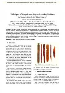
Screw extruders are the most common plastics processing machinery used today. They operate by converting a flow of thermoplastic material and additives into a well mixed continuous melt stream. Extruder design, as shown in Figure 1, consists of a screw(s) housed within a thickwalled barrel forming a channel between the root of the screw and the encasing wall. Material residing within this channel is mixed, melted and conveyed by helical flights on the rotating screw. The process can be divided into three zones common to all screw configurations. Beginning at the feed hopper, thermoplastic resins in the form of beads, pellets or powder along with desired additives are fed directly into the feed throat. This feed zone contains deep channels and long screw flights that initiate the process by filling the channel, building a pressure gradient and conveying the unmelted ingredients into the barrel. Next, the material enters the transition zone, also known as plasticating zone, where energy is imparted to heat the polymer to its melting point. Characterized by a decreasing channel volume, the transition zone compresses the unmelted material, eliminates air pockets and further increases the pressure. The ingredients are mixed and plasticized as screw motion within this packed bed of material generates intense shear. In this zone, much of the extruders mechanical energy is converted into frictional heat with additional external heat applied through the barrel wall. External heat is usually provided by a series of electric resistance heaters. Cooling, 1
THROAT
MOTOR
BARREL
\ REDUCER
INSULATED BARREL
CLOSED-LOOP COOLING SYSTEM
Figure 1. Side view schematic of plastics extruder.
1
necessitated by the buildup of frictional heat is provided by cooling fans or by circulating liquid coolant. The temperature is precisely controlled by solid state PID controllers. Finally, in the metering or pumping zone, located at the screw tip, a sharp decrease in channel volume further compresses the melt and increases the melt pressure in order to pump the material against the die pressure. Extruders can be run open-ended or with a die appropriately designed for the processing requirements. Throughout the process, screw motion serves to advance the material while applying shear to blend the polymer and additive. Screw extruders, even when equipped with venting screws, have limited ability in removing residual moisture in excess of 5 wt% of the feed material. Volatiles or evolved gases that remain trapped within the melt can result in the formation of undesirable voids or bubbles in the final solidified product. When using screw extrusion for waste encapsulation, varying degrees of pretreatment such as drying or size reduction may be required to make them amenable to processing due to the wide range of chemical and physical properties of waste materials. Screw extruders are primarily classified by the number of screws they contain. This report will focus on the two most common screw extruders, the single-screw and twin-screw extruder. Other variations include two-stage compounding extruders, reciprocating-screw kneader, concentric-screw extruders and many more. Manufacturers of a variety of plastic extruders, including both single and twin-screw extruders, are listed in the Appendix. 2.1
Single-Screw Extruders
Single-screw extruders are well proven in the plastics industry for thermoplastic processing, using virgin and recycled polymers, and for selected compounding applications. This may include compounding fillers, colorants and additives with a wide variety of different thermoplastics. This broad range of applications is made possible through numerous screw configuration options. The choice of screw type depends largely on the physical properties (liquid/solid compatibility, bulk density, specific gravity, etc.) of the materials being processed as well as the level of mixing and productivity desired. The basic screw design consists of feed, transition and metering sections with 2
uniform screw flights. Advancements in screw configuration have led to the incorporation of second flights, interrupted flights, high-shear barriers and various types of mixing sections in order to improve performance. Every screw design, however, is a compromise between productivity, melt temperature, degree of mixing and output uniformity. Examples of some generic screw types are shown in Figure 2.
Feed
Transition
Metering
Feed
Basic Metering Screw Feed
Transition
Metering
Maddock Mixing Screw Feed
Transition
Trans.
Meter
Vent
Meter
Two-Stage Venting Screw Feed
Barrier
Metering
Qs^WK^Barrier Screw
Metering
Feed
Pin Mixing Screw
Barrier
Metering
Barrier-Maddock Mixing Screw
Figure 2. Various screw types available for extruders.
4
The Basic Metering Screw is a standard single-stage screw design comprised of the three zones described above. Although still utilized for the extrusion offiberand polyvinyl chloride (PVC) compounds, this screw has relatively limited mixing capabilities. Improved mixing is provided by the Maddock Mixing Screw which employs a close-clearance mixing section to deliver added shear. Higher melt temperatures normally associated with increased shear are controlled by placing the mixing section in an area of the barrel subject to heating and cooling. This is a simple task since most extruders are equipped with temperature controllers along the entire length of the barrel. An alternate mixing mechanism is provided by the Pin Mixing screw which contains multiple rows of pins that break channel circulatory flow patterns to enhance blending without significantly increasing shear. The Barrier Screw design provides an improved melting mechanism by separating melt and solids channels using offset barrier flights. This results in increased output and/or reduced melt temperatures, and improved pressure stability. The Maddock mixing section can also be integrated with the Barrier Mixing Screw. Another design option is the Two-Stage Venting Screw. In this option a feed, transition and metering section in the first stage dumps into a deep-channel area followed by a recompression and pumping zone within the second stage. Venting of volatile gases can be accomplished through vent ports within the let-down section. Additional variables controlling product quality include screw flight pitch angles, length to diameter ratio (L/D) and operational controls. Furthermore, modifications to barrel design may include grooved or tapered sections used to enhance throughput. 3
Years of proven application within industry make single-screw extruders a very dependable technology yielding advantages in its simplicity, operating ease, low maintenance and great versatility at lower operating costs when compared to other competing processes. For some demanding compounding applications, however, single-screw extruders may not provide the same level of mixing as other processing techniques with added difficulties in dispersing extremely fine particles (mean particle size < 50um). However, recent advances in screw designs, sophisticated control systems and modified feed mechanisms have addressed many concerns associated with single-screw extrusion. 2.2
Twin-Screw Extruder
The twin-screw extruder, designed with two screws placed side-by-side, has proven versatile for handling difficult compounding jobs such as glass-fiber, high loading fillers and heterogeneous plastics. Screw arrangement can be tailored to meet distinct processing requirements, allowing improved control of critical operating parameters such as residence time, degree of shearing and processing temperature. In addition, intermeshing screw flights deliver a unique forced-conveying or pumping property that considerably broadens the conveying capabilities of this type of extruder. As a result, the twin-screw extruder can function like a positive screw-type pump to handle difficultto-feed materials. Options in screw configuration can further expand versatility through the addition of intense mixing and shearing elements, venting zones or a variety of process specific devices. As shown in Figure 3, twin-screws are normally categorized as either co-rotating or counter-rotating with further classification of intermeshing and non-intermeshing designs. A new line of reversible intermeshing twin-screw machines can operate in both co-rotating and counter-rotating modes. Co-rotating screws are commonly used in processing nylon, thermoplastic polyester, polypropylene and styrenics. In this configuration, two screws rotate in the same direction, deflecting the ingredients on a figure eight pattern around both screws resulting in an excellent exchange of material. At the same time, small uniform clearances between intermeshing screw flights yield an even residence time for each melt particle while also helping to eliminate dead spots. Co-rotating screws, however, are limited to conveying material through drag flow mechanics whereas counterrotating intermeshing design can operate as a positive-screw type pump, thereby broadening its range of application. A counter-rotating intermeshing arrangement can also provide greater control of mixing, shearing and conveying properties by regulating the amount of clearance between the screws. For example, narrowing the gap generates higher shear as material is forced through a smaller opening but lowers output with less area for longitudinal transport. Non-intermeshing counterrotating screws are open both lengthwise and crosswise to promote generous mixing of material between screws as well as conveying material at higher outputs. However, this "open" design limits the control over and degree of shearing the screw can impart.
4
Corotatmg
Counterrotating
Figure 3. Types of screw configurations for twin-screw extruders.
1
Twin-screw extruders were developed to overcome many of the difficulties realized in singlescrew extrusion. Some advantages claimed over single-screw extruders include greater versatility for compounding "difficult to mix" materials and closer control of shear and temperature parameters. In addition, the gear-pump effect makes it possible to accept difficult-to-feed material as well as allowing for multiple downstream feed zones that can eliminate the need for pre-blending. Material pretreatment requirements are similar to those found for single-screw extruders but due to improved dispersive mixing in twin-screw extruders a broader particle size range may be tolerated. Disadvantages of twin-screw extruders compared with single-screw are higher capital costs and higher operating costs due to more frequent and costly maintenance requirements and more complicated operations. Pretreatment is still required for most wastes for successful processing with twin-screw extruders.
3.
CONTINUOUS MIXERS
Continuous mixers are mixing machines designed to yield the same level of mixing found in batch mixers but in a continuous process. Applications include compounding thermoplastics, polyolefins, rubber compounds, engineering resins and vinyl compounds. Similar to twin-screw extruders, the continuous mixer is designed with two adjoining cylindrical rotors housed in a closefitting twin bore casing as shown in Figure 4. The non-intermeshing counter-rotating rotors generally consist of two sections, a feed screw portion and a bladed mixing zone. Ingredients are starve fed to the deep channelled screws in the feed throat, then continuously transported to the rotors in the mixing chamber. The mixing chamber contains rotating agitators with flights that extend down the length of each rotor in a roughly helical form reversing its pattern at the rotor midpoint. Unmelted ingredients entering the mixing chamber are carried forward by the forward helix and back against the flow by the reverse helix resulting in an intense fluxing action that thoroughly mixes the ingredients. As the material is fluxed it is also forced to pass between the rotating tangential blades 5
•
Figure 4. Side view schematic of Farrel continuous mixer.
6
and the barrel wall generating shear. Additional mixing is provided as kneading and rolling actions enhance lateral interchange of material between the two rotors. A combination of frictional energy and external electrical heaters serve to melt the ingredients as the desired mixing, fluxing or mastication takes place. Finally, the homogenous melt progresses down the rotor towards the discharge orifice gate which, unlike the discharge end/die in screw extruders, must be narrowed or widened to control throughput. Varying the discharge orifice gate opening can increase or decrease the working volume of material in the chamber, and reduce or enhance the intensity of mixing and shear. Additional variables which control operating conditions include rotor speed, temperature controls and feed rate. Farrel Corporation and Pomini, Inc. are two manufacturers of traditional continuous mixers and both offer many variations on the standard rotor design, as shown in Figure 5. Choices in blade configuration and arrangement can improve specific operational parameters for applications with temperature sensitive materials, residence time critical material or high filler loading requirements. Similar to screw designs, a let down zone can also be incorporated for downstream feeding or venting. Other designs include the Pomini Long Continuous Mixer (LCM), shown as the first stage of Figure 6, which adds a second mixing chamber that nearly doubles the rotor length to yield longer residence time and improved mixing quality at high production rates. Effective processing of fine particles and higher filler loadings is also made possible. Lacking the pressures required for extrusion or pelletizing operations, continuous mixers also offer the option of discharging the material from the mixing chamber through the orifice gate directly into a screw extruder as shown in Figure 6. The addition of this second stage can improve mixing and temperature control as further blending, heating and/or cooling can take place while sufficient pressure is developed for pumping the melt through a discharge die.
6
3 cQBCCtttB No. 7: • For temperature sensitive materials. • Less intensive than No. 15.
No. 15: • All purpose mixing and compounding for every mixer size. • Standard for concentrates and high filler loadings.
No. 24X: No. 22: • For high levels of • Special for residence devolitilizing. time critical materials. • For downstream addi- • Devolitilizing tion of high percentage components (up to 50%) such as fiberglass and talc. • Excellent for difficult dispersion requirements.
Figure 5. Rotor options for Farrel continuous mixer.
7
Advantages in continuous mixers include improved mixing quality, high additive loading capacity and the ability to handle difficult-to-mix compounds. These benefits, however, come at a significantly higher capital cost compared to screw extruders. Furthermore, with their relatively recent introduction into the plastics industry the mixers have yet to develop the same type of versatility found in screw designs. Continuous mixer designs also demand a starved feed section be maintained, complicating normal operational requirements. Sustaining a starved condition for a desired mixing quality and production rate (equal to feed rate) demands a careful balance between orifice setting, rotor speed and temperature controls. Start-up is also complicated by requiring a -Feed Throat
/Vent Port
Figure 6. Long continuous mixer with a second stage single-screw extruder. 7
11
closed orifice gate that must be opened in increments such that only melted material is discharged. Continuous mixers can be used for waste encapsulation processing but waste pretreatment may be required as with extrusion. Maximum moisture content that can be tolerated is approximately 5 wt% and although having improved compounding abilities, particle size is limited to no greater than 6mm. 4.
HIGH-SHEAR MIXERS
The major distinction between these devices and the compounding machines already described is that high-shear mixers operate as a batch process and without external heaters. By processing in a batch mode, they are capable of delivering a high level of mixing unattainable in the continuous screw designs. Although some differences exist, the general operations of high shear mixers begins with measured quantities of polymer and additives being fed through the top of the machine and into a mixing chamber. Here, blades of various designs and arrangements rotate at high speeds producing the desired modes of mixing, fluxing, mastication or shearing. Once the material reaches a predetermined parameter (temperature, energy or residence time), it is discharged as a molten mass through a door at the bottom of the machine. At this point the process cycle is complete and the mixer can be readied for another batch. Controllable variables in mixer operations are limited to blade or rotor speed, degree of heating/cooling and residence time. Two types of mixers popular in compounding polymers include the intensive internal fluxing mixers also known as Banburys and the high-intensity fluxing machine. Banbury mixers, introduced by Farrel Inc., operate with two counter-rotating rotors that revolve at slightly different speeds. Melting and homogenization occurs in a similar manner to the continuous version of the mixer described earlier (see Continuous Mixers) with different models varying in rotor design (intermeshing, co-rotating, etc.) cooling system, discharge mechanism and drive arrangements. High-intensity fluxing mixers operate with a very powerful drive and are distinguished by a single rotor mounted with staggered blades placed at various angles. Examples of this type of mixer include the Gelimat, manufactured by Draiswerke, Inc. (shown in Figure 7) or the LEX Processor, by LEX Technologies
INTEGRATED SCREW FEED DRIVE
ADJUSTABLE TEMPERATURE CONTROL PANEL DISCHARGE DOOR
Figure 7. High-intensity Gelimat fluxing (thermokinetic) mixer. 8
1
Inc. Revolving at high speeds (blade tip speeds up to 45 meters per second), the rotor produces a fast-paced mixing action that causes a rapid temperature rise as intense shearing transfers mechanical energy to heat. This thermokinetic heating of the batch serves to melt the material without the use of an external heat source. Material impingement against the blades and chamber wall provide the necessary mixing and dispersion of ingredients. The large drives can also help shorten production cycles (5-50 seconds) for a variety of applications including PVC, polypropylene, thermoplastics, regrinds and co-mingled recycled and virgin plastics. Major advantages to these mixing devices include simplified operations, low energy and maintenance costs and highfillerloading capacities. High-intensity mixers can process a wide range and combination of ingredients,frompliable to extremely rigid materials, without changes to machine parts as might be required for screw extruders. Such versatility can reduce down-time and simplify encapsulation processing requirements when several plastic/waste combinations are employed. Batch processing allows each particle to receive the same amount of work, improving control of residence time, temperature and product uniformity, while simplified feeding increases the range of polymers and additives that can be compounded. High shear mixers are able to process materials containing up to 50 wt% moisture, reducing or eliminating material pretreatment requirements. Operating at atmospheric pressures, volatiles are continuously vented throughout a production cycle. Disadvantages of high shear mixers involve batch charging and discharging which can affect productivity and batch-to-batch product consistency as well as greater difficulty in precisely controlling melting and mixing. This is due to the extremely high blade speeds and rapid cycle times. LEX Technologies has investigated overcoming batch limitations by using their high shear mixers in a two stage processing scheme in which molten material discharged from the mixer is fed directly to a single-screw extruder. This creates a continuous compounding operation with potentially improved product consistency over mixers alone. In this configuration the mixer not only blends both polymer and additives into a molten mass but also serves as a waste pre-processing step, grinding and drying materials normally unsuitable for single-screw extrusion. With appropriate mixer capacities and short cycle times the batch mixing process can be successfully used to feed melt to the singlescrew extruder in the second stage. Operating primarily as a melt pump, the extruder builds pressure to deliver material through a die while further blending and heating and/or cooling takes place. Expected increases in costs and more complicated operations and maintenance requirements are countered by anticipated savings and ease from reduced or eliminated pretreatment steps.
5.
ALTERNATIVE PROCESSING TECHNIQUES
Successful waste encapsulation is not limited to screw extruders and mixing devices. Other processing techniques capable of heating and mixing both polymer and waste include vertical thin film evaporators and screwless extruders. A thin film evaporator is a drying device that takes advantage of an enlarged surface to volume ratio for quick and efficient heating and vaporization. Waste material and thermoplastic resins are fed at the top of the evaporator, spread into a thin layer and conveyed through the device by gravity flow. Externally applied heat serves to simultaneously 9
dewater the waste and melt the polymer while material flow creates limited mixing for microencapsulation. The end product is a molten mixture that exits in a continuous operation out the bottom of the thin film evaporator. This unique processing scheme takes advantage of waste pretreatment (drying) technology to melt and mix for polymer encapsulation. As a result the need for waste pre-processing can be either reduced or eliminated. However, feed materials are required to be free-flowing so pretreatment in the form of grinding or reduction would be required for large bulky materials. Thin film evaporators are also limited by high viscosity melts that occur with many thermoplastics and at high waste loadings resulting in disrupted gravity conveyance and material discharge problems. Despite using low molecular weight and low viscosity wax, tests conducted by Rocky Flats Plant indicate a limited maximum waste loading of 40 wt% compared to maximum waste loadings of 70 wt% using extrusion for selected wastes . 19
20
Screwless extrusion devices have been in existence for years, including disk-type extruders, gear pumps, planetary-gear extruders, roller extruders and ram extruders. Many of these devices were designed to meet unique requirements of specific processing applications and therefore lack the versatility and productivity found in the conventional screw design. The rotary screwless extruder design, however, has found renewed interest within the plastics industry as recent innovations in this technology promise higher operating rates, improved product quality and lower processing costs when compared to conventional extruders. The rotary screwless extruder is a continuous processing device that employs a smooth drum which rotates on an off-center axis inside a grooved chamber. Quick and efficient heating is facilitated through a combination of small clearances between rotating cylinder and barrel and a larger surface area contact between mixture and heated chamber wall. The resulting increased shear and improved heat transfer serves to expedite the melting process, reduce residence time and cut energy costs. Instamelt Systems Inc. introduced an extruder in which material is auger fed to the chamber, melted and pumped under pressure through an exit port at the top of the unit. Applications for the screwless extruder include blownfilmand sheet as well as pelletizing postconsumer recycled flakes, compounding and alloying. Only with its recent innovations in design has screwless technology achieved performance levels comparable to traditional screw extruders. Although promising, this technology lacks versatility for the wide spread applications encountered in the compounding industry.
6.
EVALUATION OF PROCESSING TECHNIQUES
There are many technologies, each with a multitude of variations, that can melt and mix polymers with additives. Choice of proper machinery for the thermoplastic encapsulation process demands careful consideration of the processing requirements involved and acceptable compromises. Factors to be considered include: pretreatment requirements, desired quality of mix, product quality, waste form requirements, ease of maintenance and operations, temperature and pressure sensitivity, overall production capacity and both capital and operational/maintenance costs. Homogenization of waste materials with selected thermoplastics is of paramount importance if solidified final waste forms are to meet the performance requirements specified by the Nuclear 10
Regulatory Commission (NRC) ' and the Environmental Protection Agency (EPA) . Poor mixing can produce areas of high waste concentrations both within and on the outer surface of the final monolithic waste form, increasing exposure of waste to leaching pathways. Therefore, the degree of homogenization required is largely governed by the encapsulated waste's ability to meet minimum leaching requirements. Experience with single-screw extruders has demonstrated successful mixing quality in encapsulation of a wide range of wastes including aqueous evaporator concentrates (nitrates, chlorides, sulfates, borates), sludges, blowdown solutions, molten salt oxidation salt residuals, soils and soilwashing residue, incinerator fly and bottom ash and ion exchange resins. Although improved mixing may be delivered in twin-screw extruders and still better blending in both continuous and high-shear mixers, BNL has been successful in generating homogenous waste forms with a wide range of waste types that surpass NRC and EPA waste form performance guidelines using single screw extrusion ' ' . Rocky Flats Plant is currently investigating encapsulation using twin-screw extrusion but no significant waste loading and product performance improvements have been demonstrated . 21 22
23
24 25 26
19
Product uniformity and consistency can significantly affect the encapsulated waste's ability to meet quality assurance requirements. High-shear mixers, operating in a batch process, can deliver superior uniformity over continuous machines as each particle is ensured an equivalent amount of heating, mixing and residence time. The very same batch process, however, adversely affects the machines ability to deliver acceptable levels of batch-to-batch product consistency. As a result, continuous machines have an advantage. Precise metering of materials entering continuous compounders, through automation and control systems, can produce excellent product dependability. Simplified operations and maintenance requirements are vital in minimizing risk of contamination and/or harm to operators when hazardous waste materials are involved. Overall, processing operations are easiest for high-shear mixers followed by single-screw extruders, twinscrew extruders and continuous mixers. However, high-shear mixers are batch processors and therefore demand considerable operator attention. With regard to ease of processing, extruders, especially single-screw extruders, are the preferred choice. Many of these devices offer a varying degree of temperature, pressure and rate control. These parameters can affect viscosity, flow and solidification time. Regulation of pressure, temperature and throughput can affect mixing characteristics and thus final waste product consistency. All of the processing techniques investigated are designed to meet these process control requirements. However, extruders offer the most precision in controlling process parameters. With state-of-the-art control systems extruders are capable of maintaining zone temperatures within ±1°F. Finally, cost and production considerations must be evaluated. The processes examined are available in a wide range of production capacities, all of which encompass the expected capacity demands for polyethylene encapsulation of waste. In comparing the relative cost of each technology the high-shear mixers were determined to be the most economical. For a production capacity of 2000 lbs/hr, the technologies from least to most expensive are the high-shear mixer ($190,000), singlescrew extruder ($230,000), continuous mixer ($400,000), twin-screw extruder ($430,000), mixer 11
($550,000) and the Compact Compounder ($650,000). These costs are based on manufacturer's estimates for typical processing equipment and may vary. This analysis does not consider maintenance/operational costs, savingsfromenergy efficiencies nor the added cost for integrating pretreatment, feeding, quality control monitoring and process controls. Each processing technology has requirements and limitations on the physical properties of the additives or waste materials that are to be mixed with polymers. Waste materials that require stabilization and solidification invariably have diverse physical properties. Therefore, some degree of pretreatment may be required to make the waste materials amenable to polymer processing. Twinscrew extruders and continuous mixers can be successfully used for waste encapsulation, and may tolerate a broader particle size distribution of waste materials with potentially improved mixing compared with single-screw extruders. Batch processing in high shear mixers show even greater improvement for reducing waste pretreatment by processing a broader range of waste types and tolerating higher moisture levels. However, a methodical analysis of the processing needs versus the relative merits and limitations of each of the compounding technologies reviewed reveals that considering demonstrated performance, ease of operation and cost effectiveness single-screw extrusion appears to be the best choice for most waste encapsulation needs. BNL has demonstrated on bench and full-scale tests, that single-screw extrusion combined with appropriate waste pretreatment is a simple, cost-effective and successful encapsulation process. Wastes with high moisture contents, low bulk-density and difficult-to-mix particle sizes (fines < 40 urn) may be successfully and economically processed by coupling a high-shear mixer with single-screw extrusion. This option can reduce or eliminate pretreatment needs to further simplify the encapsulation process while potentially reducing overall costs.
12
REFERENCES 1.
Frados, J. eds., "Machinery and Equipment", Plastics Compounding Redbook, Vol. 8, No.6, pp. 108-124, 1985
2.
Cheremisinoff, N.P., Polymer Mixing and Extrusion Technology. Marcel Dekker, Inc., New York, 1987.
3.
Schenkel, G., Plastics Extrusion Technology and Theory. American Elsevier Publishing Company Inc., New York, 1966.
4.
Davis Standard, Manufacturers Product Literature, "Knowing Your Extruder"
5.
Gaspari, J.D., "Twin-Screw Compounders and Reclaim Extruders From New Source", Plastics Technology, Vol. 48, p.26, October 1990.
6.
Farrel Corporation, Manufacturers Product Literature, "Principles of Operation, Farrel Continuous Mixer", 1992,
7.
Farrel Corporation, Manufacturers Product Literature, "Continuous Mixers for the Polymer Industry", 1993.
8.
Farrel Corporation, Conversation with Sales Engineer, Vincent J. Gaccione, April 27, 1995.
9.
Pomini Inc., Manufacturers Product Literature, "Pomini Technology, LCMAX", 1994.
10.
Farrel Corporation, Manufacturers Product Literature, "CP-Series II Compact Processor", 1994.
11.
Pomini Inc., Manufacturers Product Literature, "LCM Long Continuous Mixer and CC Compact Compounder"
12.
Draiswerke Inc., Manufacturers Product Literature, "Drais News", Vol. 1, No.4
13.
Lex Technologies Inc., Manufacturers Product Literature, July 9, 1994.
14.
Lex Technologies Inc., Conversation with Vice President, Douglas Sangster, May 25, 1995
15.
JGC Corporation, Manufacturers Product Literature, "Advanced Radwaste Facilities", p.12
13
16.
Ogando, J., "Redesign Boosts 'Screwless' Extruder Output", Plastics Technology, Vol. 38, p. 55, April 1992.
17.
Berstorff Corporation, Conversation with Sales Representative, Jeff Kerrigan, May 16, 1995.
18.
Draiswerke Inc., Conversation with Sales Engineer, David Rice, April 17, 1995
19.
Faucette, AM., B.A. Logsdon, J.J. Lucerna. and RJ. Yudnich, "Polymer Solidification of Mixed Wastes at the Rocky Flats Plant," Waste Management '94, Volume 3, R.G. Post, eds., Proceedings of the Symposium on Waste Management, Tucson, AZ, February 27March 3, 1994.
20.
Kalb, P.D., J.H. Heiser and P. Colombo, "Polyethylene Encapsulation of Nitrate Salt Wastes: Waste Form Stability, Process Scale-up, and Economics," BNL-52293, Brookhaven National Laboratory, Upton, NY, July 1991.
21.
U. S. Nuclear Regulatory Commission, "Licensing Requirements for Land Disposal of Radioactive Waste, "Title 10 of the Code of Federal Regulations, Part 61, US NRC, Washington, DC, May 1983.
22.
U.S. Nuclear Regulatory Commission, "Technical Position on Waste Form, Revisionl 1, "Final Waste Classification and Waste Form Technical Position Papers, US NRC, Washington, DC, January 1991.
23.
U.S. Environmental Protection Agency, Toxicity Characteristic Leaching Procedure, 40 CFR 261, Fed. Reg. 55, 11863, March 29, 1990.
24.
Kalb, P.D., and P. Colombo, "Polyethylene Solidification of Low-Level Wastes," BNL51867, Brookhaven National Laboratory, Upton, NY, October 1984.
25.
Kalb, P.D., and M. Fuhrmann, "Polyethylene Encapsulation of Single-Shell Tank Wastes," BNL-52365, Brookhaven National Laboratory, Upton, NY, September 1992.
26.
Kalb, P.D., J.H. Heiser, and P. Colombo, "Long-Term Durability of Polyethylene for Encapsulation of Low-Level Radioactive, Hazardous and Mixed Wastes," Emerging Technologies in Hazardous Waste Management III, D.W. Tedder and F.G. Pohland, eds., American Chemical Society Symposium 518, Washington, D C , 1993.
14
APPENDIX MANUFACTURERS OF PRODUCTION-SCALE THERMOPLASTIC PROCESSING EQUIPMENT SUPPLIER
LOCATION
TELEPHONE
EXTRUDERS: Berstorff Corporation
8200 Arrowridge Blvd. P.O. BOX 240357 Charlotte, NC
704-523-2614
C.W. Brabender Instruments Inc.
P.O. BOX 2127 South Hackensack, NJ 07606
201-343-8425
Cincinnati Milacron
4165HalfacreRd. Batavia, OH 45103
513-536-2000
Davis-Standard Div., Crompton & Knowles Corporation
One Extrusion Dr. Pawcatuck, CT 06379
203-599-1010
Farrel Corporation
25 Main St. Ansonia, CT 06401
203-736-5500
Wayne Machine & Die Company
100 Furler St. Totowa, NJ 07512
201-256-7374
C.W. Brabender Instruments Inc.
P.O. BOX 2127 South Hackensack, NJ 07606
201-343-8425
Draiswerke Inc.
40 Whitney Road Mahwah, NJ 07430
201-327-3151
Farrel Corporation
25 Main St. Ansonia, CT 06401
203-736-5500
LEX Technologies Inc.
1100 Abernathy Road, Suite 625 Atlanta, GA 30328
404-551-8277
Littleford Day Inc.
7451 Empire Dr., Florence, KY 41042
606-525-7600
Werner & Pfleiderer
663 E. Crescent Ave. Ramsey, NJ 07446
201-327-6300
HIGH SHEAR MIXERS:
15
SUPPLIER
LOCATION
TELEPHONE
CONTINUOUS MIXERS: C.W. Brabender Instruments Inc.
P.O. BOX 2127 South Hackensack, NJ 07606
201-343-8425
Farrel Corporation
25 Main St. Ansonia, CT 06401
203-736-5500
Pomini Inc.
6400 W. Snowville Rd. Brecksville, OH 44141
216-838-0500
16