K.Fong, M. Laverty, S. Fang, TRIUMF, Vancouver, BC, Canada. Abstract. The ISAC RF system consists of a radio frequency quadrupole accelerator, five drift ...
Proceedings of the Second Asian Particle Accelerator Conference, Beijing, China, 2001
RF CONTROL SYSTEMS FOR THE TRIUMF ISAC RF K.Fong, M. Laverty, S. Fang, TRIUMF, Vancouver, BC, Canada Abstract The ISAC RF system consists of a radio frequency quadrupole accelerator, five drift tube LINACs, seven bunchers, a dual frequency chopper and a bunch rotator. With the exception of the prebuncher, which required a sawtooth waveform, the other cavities have cavity Q's in excess of 5000 and are either excited with the fundamental frequency of 35.36 MHz, with the third harmonic frequency of 106.08 MHz or with subharmonic frequencies of 5.893MHz and 11.786 MHz. All are running synchronously and are individually amplitude and phase regulated. A hybrid rf control system uses analogue components to provide front end rf detection and digital signal processors to provide closed-loop amplitude, phase and tuning control. A single feedback circuit is employed for each cavity. This system, as well as the frequency synthesis and distribution system, is described in this paper.
corresponds to a VXI module with the exception of the power splitters. Frequency synthesizer 1 is the master frequency source. It uses a 10 MHz crystal reference oscillator. The 10 MHz signal is frequency multiplied to 80 MHz. A direct digital synthesizer uses this 80 MHz reference to provide the 5.893 MHz sub-harmonic frequency. Non-linear frequency triplers are used to generate 11.786 MHz and 35.36 MHz frequencies, with a frequency resolution of 6 Hz at 35.36 MHz. Other frequency synthesizer modules are slaved to Frequency Synthesizer 1 and also use harmonic generation to produce the different harmonics for the pre-buncher and 106 MHz for the DTL’s and bunchers.
1 INTRODUCTION The ISAC rf system can be divided in three sections: the low energy section, which includes the prebuncher and the RFQ accelerator; the medium energy section, which includes the dual frequency chopper, the bunch rotator, the DTL linac’s and their bunchers; and lastly the high energy section, which includes the two single frequency choppers. The most complex sub-system in the rf control system is the frequency distribution system. This system has to provide four different frequencies to 16 different rf regulators. These rf regulators enable the automatic sequencing of the powering up process, and once the cavities are powered up they provide amplitude and phase regulation. The cavities also need to be tuned to their operation frequencies. Tuning control uses a signal derived from the phase regulation and drives a stepping motor, which in turn moves a metallic plate inside a cavity. The entire system is housed inside 6 VXI mainframes distributed along the length of the linear accelerator. An earlier version of the basic rf control system for the RFQ was documented in a previous paper[1]. It also shares some elements with the prototype design for the prebuncher[2]. Since that time, the frequency distribution system has been added, the DTL linacs have been commissioned, and the bunchers and choppers brought online. As well, a number of basic design changes involving both hardware and software have been introduced, some of which have been retrofitted to the prebuncher and RFQ control systems.
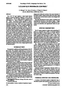
2 FREQUENCY DISTRIBUTION SYSTEM A block diagram of the frequency distribution system is shown in Figure 1. Each of the blocks in this figure
Figure 1-Block Diagram of Frequency Distribution System Each frequency distribution module has two separate channels, and each channel provides one buffered and one software adjustable phase shifted/buffered output. Each phase shifted output can provide phase shift over a range of 800o with 0.1o resolution. This particular topology was arrived at after various cavities had been added at different stages of construction. For example, after operating the beam through the DTL chain, it was realized that a group phase adjustment would 642
Proceedings of the Second Asian Particle Accelerator Conference, Beijing, China, 2001
be desirable. This would allow the operator to change the phase of every cavity within the DTL chain relative to the phase of the RFQ. The addition of Distribution Module 0 makes this phase adjustment possible, and permits compensation for the aging of a target foil located in a drift tube some distance away from the DTL chain.
3 RF CONTROL SYSTEM A typical rf control system consists of a desktop PC, a VXI slot zero control module, and two custom modules housed in a VXI mainframe. A block diagram of the overall system is shown in Figure 2, while Figure 3 shows the rf controls in more detail. The VXI mainframe provides a clean environment for the two control modules which regulate rf signals. One of these provides the rf modulation and demodulation function, while the second performs digital signal processing of the demodulator signal. A control system typically consists of 4 loops: a phase-locked loop for phase stabilization, an in-phase and a quadrature-phase regulating loop for rf amplitude/phase regulation, and a
cavity tuning loop for proper impedance matching to the rf amplifiers. For stability reasons, for proper operation in selfexcited mode, as well as to reduce the cross talk between the two loops, the rf phase around the I/Q loop at resonance is adjusted to be an integer multiple of 360o. In this configuration one can also derive the signal necessary for tuning control from the Q loop. This will be described in the next section. Feedback loop regulation, requiring high signal bandwidth, is performed on-board using Motorola digital signal processors. With a sampling rate of 400 kHz, a control bandwidth of 20 kHz is achieved with the Motorola DSP56002 processor. Supervisory tasks, which require low signal bandwidth but relatively complex decision logic, are performed with the desktop PC. Communication between the PC and the VXI mainframe is done via a FireWire (IEEE 1394) interface. Communication between the PC and the central control system is done via 100BaseT ethernet. Up to 4 independent rf systems can be housed inside a VXI mainframe and be controlled by a single control PC.
Figure 2 – System Block Diagram
4 CAVITY TUNING SYSTEM The cavities are tuned by a pair of grounded capacitive plates extending inside them. The plates can be moved in or out by a leadscrew. For the coarse tuner the plate is moved manually, while the fine tuner moves the plate by a stepping motor. The cavity tuning system make uses of the fact that the rf phase around the I/Q loop at resonance is an integer multiple of 360o. As a result, at resonance the Q input to the feedback controller is zero and the Q modulation is zero. Any detuning is manifested as the presence of signal at the Q input when the Q loop is opened, or the presence of Q modulation when the loop is closed. To allow automatic tuning in both open and closed loop conditions, the weighted sum of the input and the output of the Q PID is used as the error signal for the tuning controller. In this way, The Q loop serves dual purpose: as a regulating loop for rf signal as well as an
out-of-tune detector for the tuning loop. In order for this to happen, as well as to eliminate quadrature error, the set point of the Q loop must be set to zero, and the phase of the cavity is set by changing the reference input via the frequency distribution system.
5 SYSTEM SOFTWARE There are two distinct software designs incorporated in this system. One is the low level feedback control firmware for the DSP. In order to be able to achieve the highest processing speed this software is hand coded in assembler. It performs open and closed loop regulation, output limiting, as well as exchanges of status information with the supervisory processor. The supervisory processor performs the tasks of automatic power up sequencing, local status display, and communication with the remote EPICS-based master control system. Since each VXI mainframe can house up to four rf control 643
Proceedings of the Second Asian Particle Accelerator Conference, Beijing, China, 2001
Figure 3 – RF Control Block Diagram systems, the supervisory processor can have up to five tasks running that are related to rf control. These include a separate task for each control system, and a task to control the tuning status and phase shifts to these four systems. All the tasks are written using 32 bit C++ with Windows API’s. Inter-task communication was originally performed using dynamic data exchange, but process instability forced the abandonment of this method, and the more stable method of UDP/IP packets is now used. Communication with remote control also uses UDP/IP for parameters that are to be updated frequently, such as setpoint slewing. TCP/IP is used for controls that are accessed less frequently, such as ON/OFF switching.
6 CONCLUSION The system as described in this paper has been constructed, tested, and comissioned[3]. Over the span of three years, we have gain a lot of operating experience with the system, as whole as well as the behavior of each individual cavity. Modifications were performed to the
frequency distribution system and the tuning control for easier operation. The system has since been operating reliably.
7 REFERENCES [1] M. Laverty, K. Fong, S. Fang, “Design and Testing of the ISAC RFQ Control System”, Proceedings of the 1999 Particle Accelerator Conference, New York, March 1999, pp. 890-2. [2] M. Laverty, K. Fong, S. Fang, "A DSP-based Control System for the ISAC Pre-Buncher", Proceedings of the International Conference on Accelerator and Large Experimental Physics Control Systems, Beijing, November 1997, pp. 263-5. [3] K. Fong, S. Fang, M. Laverty, J. Lu, R.L. Poirier, “Commissioning of the TRIUMF ISAC RF System”, Proceedings of the 2001 Particle Accelerator Conference, Chicago, June 2001, to be published .
644