Rigorous Testing by Merging Structural and Behavioral UML Representations Orest Pilskalns and Anneliese Andrews1
[email protected] |
[email protected] and Sudipto Ghosh and Robert France2
[email protected] |
[email protected] 1
School of Electrical Engineering and Computer Science Washington State University 2 Computer Science Department Colorado State University
Abstract. Error detection and correction in the design phase can reduce total costs and time to market. Yet, testing of design models usually consists of walk-throughs and inspections both of which lack the rigor of systematic testing. Test adequacy criteria for UML models help define necessary objectives during the process of test creation. These test criteria require coverage of various parts of UML models, such as structural (Class Diagram) and behavioral (Sequence Diagram) views. Test criteria are specific to a particular UML view. Test cases on the other hand should cover parts of multiple views. To understand testing needs better, it is useful to be able to observe the effect of tests on both Class Diagrams and Sequence Diagrams. We propose a new graph that encapsulates the many paths that exist between objects via their method calls as a directed acyclic graph (OMDAG). We also introduce the object method execution table (OMET) that captures both execution sequence and associated attribute values by merging the UML views. The merging process is defined in an algorithm that generates and executes tests.
1
Introduction
Current practice in UML design evaluation is to use inspections and walkthroughs. Given that UML models for many designs can become quite large and complex, inspections and walk-throughs can be ineffective and problematic. In addition, UML provides a variety of notational views. These views in isolation cannot provide a representation of the cross notational aspects in UML. To find cross-notational inconsistencies requires transformation of the model into a representation that allows verification of integrity between views. When views are integrated, types of relationships can be discovered and validated that are not obvious in a single UML notational view. We investigate the following research questions: 1. Can we integrate structural and behavioral UML views so we can generate tests and observe the effect of tests on both?
2. Can the tests be used to satisfy structural and behavioral test adequacy criteria? This paper presents an approach to integrate two complementary views of UML designs: structural views through Class Diagrams and behavioral views through Sequence Diagrams. We then use information from both to derive and execute tests that satisfy test adequacy criteria for both structural and behavioral views. In section 2 we discuss related work and test adequacy criteria. In section 3 we examine the extraction of attributes and parameters from Class Diagrams, the transformation of Sequence Diagrams into directed acyclic graphs, and finally an algorithm that merges the structural and behavioral representations into an object-method test execution table.
2 2.1
Background and Related Work Related Work
Work on testing using the UML has tended to focus on generating requirements and criteria for code testing from UML diagrams. Binder [3] described generic code test requirements that can be derived from UML models. Offutt and Abdurazik [8] developed a technique for generating test cases for code from a restricted form of UML State Diagrams. Abdurazik and Offutt [1] also developed test criteria based on Collaboration Diagrams for static and dynamic testing of code. Building on this work, they proposed methods for statically checking code relative to a Collaboration Diagram using classifier roles, collaborating pairs, messages or stimuli and local variable definition-usage link pairs. Labiche and Briand [4] describe the TOTEM (Testing Object orienTed systEms with the Unified Modeling Language) system test methodology. System test requirements are derived from UML analysis artifacts such as use cases, their corresponding Sequence and Collaboration Diagrams, Class Diagrams and the use of OCL across all these artifacts. The test requirements are then transformed into code-level test cases, test oracles and test drivers using more detailed design information. In Scheetz et al. [10] an approach to generating system (black box) test cases from UML Class Diagrams is described. In the approach, a restricted form of UML Class Diagrams is used to represent the conceptual architecture of the system under test. The Class Diagrams used consist only of classes, associations (including aggregation), and specialization structures. From the Class Diagrams test objectives are derived that cover single classes, groups of classes, and their associations as depicted in the Class Diagrams. The work described in this paper, unlike the work described above, is concerned with testing of UML models, and, thus, is concerned with defining test criteria for testing UML models and generating tests that will be applied to UML models.
2.2
UML Testing Criteria
Andrews et al. [2] defined a family of test adequacy criteria for Class Diagrams and Collaboration Diagrams. Table 1 lists some of these criteria. As in other related work, these test criteria apply to single UML views, in this case Class Diagrams and Collaboration Diagrams. This paper uses Sequence Diagrams instead of Collaboration Diagrams, because they will no longer be part of the UML 2.0 Specification [7]. Table 1. Test Adequacy Criteria definitions. Class Diagram Criteria Association-End Multiplicity Criterion Given a test set T and a System Model SM , T must cause each representative multiplicity-pair in SM to be created. Generalization Criterion Given a test set T and a Systems Model SM , T must cause every specialization in a generalization to be created. Class Attribute Criterion Give a test set T , a System Model SM , and a class C, T must cause a set of representative attribute value combinations in each instance of class C to be created. Collaboration Diagram Criteria Condition Coverage Criteria Give a test set T and Collaboration Diagram CD, T must cause each condition in each decision to evaluate to both TRUE and FALSE. Full Predicate Coverage Criteria Give a test set T and Collaboration Diagram CD, T must cause each clause in every condition in CD to take the values of TRUE and FALSE while all other clauses in the predicate (condition) have values such that the value of the predicate will always be the same as the clause being tested. All Message Paths Criteria Given at test set T and Collaboration Diagram CD, T must cause each possible message path (sequence of message numbers) in CD to be taken at least once. Collection Coverage Criteria Given a test set T and Collaboration Diagram CD, T must cause each representative multiplicity of collection object in CD to be created.
The first set of test adequacy criteria apply to structural models and are defined for Class Diagrams. The associated-end multiplicity criteria aim at evaluating the design with respect to all class relations. An association-end multiplicity criterion requires that a set of representative multiplicity tuples must be created during a test. The creation of this set begins with a listing of all classes and the multiplicity of each class. Taking the Cartesian product of each
set of associations creates a set of configurations. Since some combinations of associations are invalid, only legitimate associations are selected [2]. The generalization criteria require evaluation of the class hierarchical structure. It defines the representative set of specialization types that must be created from a Class Diagram’s super class when testing. The class attribute test criteria focuses on the internal structure of each class. Definitions of coverage for class attributes are based on partitioning attribute domains and requiring partition coverage. Partitions can be defined based on boundary-value analysis, constraints in OCL, or domain knowledge of the tester. OCL is particularly valuable in defining partitions, since it is used in UML to restrict ranges of values, set pre and post-conditions, and boundary conditions. The second set of test adequacy criteria apply to behavioral models [2] and are defined for Collaboration Diagrams. They could easily be adapted for Sequence Diagrams, since one can be transformed into the other. The criteria defined include condition and predicate coverage, message-coverage, and all-paths coverage. This paper is mainly interested in all message paths which correspond to all possible sequences in the sequence diagram. Note that the UML 2.0 draft specification [7] prevents an unbounded number of loops to occur, making allpath coverage feasible.
3
An Integrated Testing Approach
An integrated testing approach is based on combining structural and behavioral design representations. The structural representations are UML Class Diagrams. We use the partitioning strategy of Andrews et al. [2] to define partitions and boundaries for attributes and method parameters for classes in the UML Class Diagrams. An integrated testing approach requires combining both descriptions into an integrated set of notations that allows testing of both aspects. We develop this notation by first transforming the Sequence Diagrams into Object Method Directed Acyclic Graphs (OMDAGs) see section 3.2. The values from the class attribute/parameter partitions are then associated with objects in the OMDAGs during path traversal. Due to the numbering and partitioning of the OMDAG, we satisfy, respectively, All Message Path and Attribute criteria. The resulting test information is captured in an object method execution table (OMET). It records the execution sequence and the attribute/parameter values of the generated tests. This testing method thus consists of the following steps: 1. Identify attribute/parameter partitions for all the structural elements in the design. (Outcome: Coverage items for the attribute and method parameters.) 2. Transform Sequence Diagrams into OMDAGS. (Outcome: OMDAGS.) 3. Generate paths through OMDAGS. 4. Traverse paths in OMDAGs, select and assign attribute/parameter values from partitions based on objects in OMDAG path. 5. Record results of steps 3 and 4 in object method execution table (OMET). 6. Generate and execute test cases and determine coverage of criteria using [2].
Player
1
-winnings : float -hand : Hand -drawAllowed : bool 1 +getWinnings() : float +adjustWinnings(in amount : float) +setHand(Hand)() +getHand() : Hand +drawAllowed() : bool +Player()
PokerGame
Dealer
-Player 1 +abstract deal() : Player +reset() +setBet(in amount : float) +getBet() : int +getPlayer()
1 1
-arrayOfCards +shuffle() +getHand() : Hand +getHand(in hand : Hand) : Hand +Dealer()
1
1 Hand
1
-card1 : String -card2 : String -card3 : String -card4 : String -card5 : String +discardArray +Hand()
Stud +Stud() Draw
Wild -wildCard : String
+Draw() +drawCards(in hand : Hand) : Player 1
+Wild() +drawCards(Hand)(in hand : Hand) : Player
1
1
1 MainWindow -game : int 1
1
+refresh() +playDrawPoker() +playWildPoker() +playStudPoker() +displayDealButton() +displayPlayerInfo() +MainWindow()
Fig. 1. A UML Class Diagram for a video poker game.
3.1
Partitions for the Structural Representation
For Class Diagrams, attributes and method parameters are essential for defining partitions and creating coverage items. Both attributes and method parameters provide state information for instances of a class. Different combinations of attributes define and characterize how an object interacts with other objects [3]. Partitions, including boundary-value partitions are determined by either supplementary OCL or by domain knowledge. Selection of values from each partition provides a finite set of configurations for test purposes. Figure 1 shows an example of a Class Diagram for a poker game. The values for the class Player attribute Hand can be partitioned based on poker knowledge, i.e. based on their comparative value as a winning hand. Table 2 shows this partitioning including example values. Since “Hand” consists of 5 cards, this is a second level partitioning for a group of cards. The types of hands define the coverage items. The example values indicate possible test values that cover
Table 2. Example partitioning of poker “Hand”. Type of Hand Royal Flush Straight Flush Four of a Kind Full House Flush Straight Three of a Kind Two Pair No Like Cards
Partition Definition all cards same suit Ace-to-10 all cards same suit in numerical sequence four cards with same value three cards and two cards with same value same suit but not in numerical sequence various suits in numerical sequence three cards with same value two sets of two cards with the same value no cards have the same value
Example Value 10 ♠ - Ace ♠ 2♠-6♠ 2♠2♣2♥2♦7♦ 2♠2♣2♥3♦3♣ 2 ♠ 4 ♠ 7 ♠ 9 ♠ Ace ♠ 3♠4♣5♥6♦7♦ 2♠2♣2♥6♦7♦ 7♠7♣5♥5♦3♣ 7♠2♣5♥6♦3♣
these coverage items. The types of hands also define state information for instantiated objects in the Player class. Other state information can be obtained through partitioning the other Player attributes and parameters, i.e. winnings, drawAllowed and AdjustWinnings(in Amount). For an in depth discussion of this example, see section 3.4. 3.2
The Object Method Directed Acyclic Graph as a Behavioral Representation
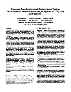
This is the second analysis step and transforms the Sequence Diagram into a format that can be navigated by a traversal algorithm that generates test sequences. A Sequence Diagram is designed to visually convey information to engineers rather than to facilitate test sequence generation. The need for a graph structure for testing prompted the creation of the Object Method Directed Acyclic Graph (OMDAG). The OMDAG transforms the behavioral information encapsulated in Sequence Diagrams and represents the information in a directed acyclic graph. The purpose of the OMDAG is similar to the purpose of the spanning tree created from a state transition diagram when trying to generate round-trip test sequences [3]: it facilitates test sequence generation. Thus the method for creating the OMDAG also bears some similarities. A Sequence Diagram consists of object nodes at the top (for example, in Figure 1 there are three such rectangular nodes marked main, dealer, and hand) and method arcs on the vertical timelines (e.g. deal(game), bet(2), return, etc in Figure 1). The OMDAG is created by (1) associating methods in the Sequence Diagram with their originating objects and (2) traversing the Sequence Diagram from beginning to end, showing choices and conditions for method execution. 1. Associate methods with objects: (a) For each method call m originating from object o create a node in the OMDAG labeled o:m(). For example, in Figure 2, the method call deal(game), from object Main, results in a node labeled Main:deal(). If
main
dealer
hand
deal(game) [game = = FiveCard] Hand(5) [game==SevenCard] Hand(7) return return
[game == FiveCard] display(5)
[game == SevenCard] display(7) bet(2) return
Fig. 2. A UML Sequence Diagram.
a message contains a condition, the condition is appended to the node’s label. (b) For each return call r from an object o in a Sequence Diagram, create a node in the OMDAG labeled o:r(). For example, in Figure 1, the return from the deal(game) method call would result in a node labeled Dealer:return(). An implicit return in the Sequence diagram also results in a node creation. In Figure 1, the method call display(5) does not have a corresponding return call because the Main object is calling one of its own methods. Sequence Diagram notation excludes these returns, however, it is clear that they are present. Since the OMDAG does not have this limitation, all return calls are explicitly shown in the OMDAG. (c) The start node in the OMDAG is the OMDAG node that corresponds to the first method call in the Sequence Diagram. In the example, see Figure 2, this is the node Main:deal(). 2. Create the OMDAG arcs by traversing the Sequence Diagram. The edges are directed to reflect the ordering of the method calls. The edges are labeled with a sequence number according to the following rules: (a) Each call must be assigned a positive integer value based upon the sequence, thus each new call will require the value to be incremented by one.
(b) A “dot” notation indicates nesting within a calling sequence. Each time a nested call is made, an additional number is appended to the sequence number (e.g. 1.1a or 1.1b refers to the nested calls made by the dealer object, note that the “a” and the “b” represent conditions). (c) For conditional statements use letters to denote the options (e.g. 1.1a and 1.1b). (d) For each loop statement, transform the loop into a series of conditional statements. This is possible because the max and min values are specified for a loop according to the UML 2.0 Draft Specification [7]. Therefore, any loop can be unrolled into a series of conditional statements. By definition the OMDAG is a directed acyclic graph. Figure 3 shows the
Dealer: Hand(5) 1.1a
[game == FiveCard
Main: display(5) 2a
1.2a
[game==Five Card]
3a 4
1.3
1 Main: deal() 1.1b
Hand: return() Dealer: Hand(7) [game == SevenCard]
1.2b
Main: return()
Dealer: return() 2b
Main: display(7)
5 Main: bet(2)
Dealer: return()
3b
[game == SevenCard]
Fig. 3. An Object-Method Directed Acyclic Graph.
OMDAG corresponding to the Sequence Diagram of Figure 2. The first method call in Figure 2 is from Main:deal(game). This creates an arc labeled “1” to the node labeled Main:deal(). The Dealer object then calls either for a Hand with five cards or a Hand with 7 cards. This reflects both nesting (i.e. no return from deal(game)) and choice. Thus the label on the arcs to nodes Dealer:hand(5) and Dealer:hand(7) are labeled according to both rules, leading to arcs 1.1a and 1.1b. The next set of arcs are returns from the Hand (Hand:return()) and labeled 1.2a and 1.2b. Next, the Dealer provides the Hand to Main, which leads to a return of the method call from Main to Dealer and an arc labeled 1.3 is created from Hand:return() to Dealer:return(). The remainder of the OMDAG is created similarly by following the rules above. 3.3
A Test Generation and Execution Algorithm
At this point there are two sources of information: the partitions for attribute and method parameter values and the OMDAG. The next step is to combine them into test sequences by (1) traversing the OMDAG, and (2) selecting appropriate attribute and parameter values for object instantiations that would cause the desired test sequence to execute.
1. Traverse the OMDAG. Given that the OMDAG is acyclic, a depth-first, or breadth first algorithm can be used to determine all paths in the OMDAG, if an all-paths test criterion is to be met. Similarly, it is straightforward to generate a set of paths that provides arc coverage, if that is the desired test coverage criterion. Let the resulting set of paths be P = P1 , ..., Pn . 2. Determine objects and values to execute paths. For each path Pi where i = 1, ..., n, do the following: (a) Determine which active objects are needed to execute Pi . There will be both explicit and implicit objects. Explicit objects are those identified in the OMDAG. Implicit objects are those objects that, while not interacting with objects in the Sequence Diagrams, are needed to bring explicit objects into states expected by the Sequence Diagram. Objects from other OMDAGs may be used. UML designs may have multiple Sequence Diagrams. These diagrams often rely on a common set of objects. If possible, the test generation for Sequence Diagrams should follow their logical execution sequence, which can be determined from domain knowledge. This assures that sets of objects that are required for a given sequence diagram have been created through a prior test of another sequence diagram. (b) Create a series of constructor calls, and if necessary, use objects from other OMDAGs, to bring the design into a set of object states expected by Pi (i.e. pre(Pi ), where pre is a set of preconditions). In doing so we use the partitions derived from the Class Diagram. Test criteria, for selecting from the partitions and constraints on the values expected by Pi , will drive the selection of values. Let this sequence of constructor and method calls be preseq(Pi ). The effect of applying preseq(Pi ) is a set of instantiated objects and object states that fulfill pre(Pi ). The details of preseq(Pi ) are recorded in an object method execution table (OMET), see Figure 6. It consists of four columns: Column 1 numbers the steps (action taken in terms of method calls or constructor calls) in the sequence in which they occur. Column 2 identifies the method call. Column 3 identifies the calling object instance. Column 4 lists the called object and its state in terms of the attribute and parameter values. In the example in Figure 6 the preseq(P1 ) consists of one constructor call that creates a MainWindow before the first method in P1 can be called. (c) Simulate the path Pi one node at a time and select and record attribute and parameter values in the OMET as follows: i. Use and assign passed values from “calling node” in Pi or from preseq(Pi ). ii. Assign and record attribute values and method-parameters for the current node in order to successfully call the next node in the OMDAG. For example, assign game == FiveCard in Figure 2. If it is not possible to call the next node, raise an exception. Return calls are not recorded. iii. If at a conditional node, assign attribute values (if possible) that meet the condition. The OMDAG records conditions along the edges
of the graph. If it is not possible (based on object partition values) raise an exception. (d) Analyze the exceptions. Exceptions arise because the state of the objects do not meet pre(n), the precondition of a node n, in a test path. This can occur for two reasons: (1) The precondition can never be satisfied. This reflects a design error. (2) Preseq(n) made a value assignment that causes pre(n) to be false. In this case different value assignments need to be made if possible. If it is not possible, either the partitions are incorrect or the there is an error in the design. (e) Use adequacy criteria to evaluate the set of tests. 3. When all tests have been defined in the OMET, it is also possible to evaluate coverage of attribute and parameter partitions, as well as all-path, message, and link coverage as suggested in [2]. Due to the nature of OMDAG test sequence generation, behavioral criteria should have been met unless a sequence is infeasible. If certain partitions are not covered, some paths may have to be executed again with value assignments from uncovered partitions. When test generation is finished, there is an OMET with attribute values and path data for every Sequence Diagram/OMDAG. These tables reflect the effect of each transition in the OMDAG and serves as repository for the “states” of the system. In addition, the association-end multiplicity, and generalization criteria can be validated using the OMETs. The procedure described above is certainly adequate, but not necessarily the most efficient. We suggest integrating it into a test process that will make it more efficient by reducing duplication of work. This test process uses rules for sequencing the analysis of Class Diagrams and Sequence Diagrams as follows: Rule 1 Analyze Diagrams for sequential dependencies, to see if they provide necessary preseq(P ) for OMDAGS of other Sequence Diagrams. This rule reduces the need for generation of preseq(P ), since they can be taken from the OMETS of design artifacts with such properties. For example, when developing tests for an Automatic Teller Machine (ATM), it is useful to develop tests for the sequence diagram SFILL, that fills the ATM with money, before developing those that take money out, SCASH, since SFILL is a preseq for SCASH. Rule 2 Reuse OMETs for partial paths, when two paths have partial paths in common at the beginning. Assume that ’|’ is a concatenation operator. Then if P1 = P11 |P12 and P2 = P21 |P22 and P11 = P21 , then OMET(P11 ) = OMET(P21 ) and only P22 needs to be executed (preseq(P22 ) = preseq(P1 )|P11 ). This rule is particular effective when branches in the OMDAG occur towards the end of the graph. 3.4
A Simple Example
In this section we apply the integrated approach to a UML model. The UML model specifies the design of a simple interactive video poker game. The interactive video poker (IVP) is a video gaming system designed for a single user.
It includes common card games such as five-card draw, five-card stud, and wild card poker. Figure 1 shows the Class Diagram and Figure 4 shows the Sequence Diagram. In addition, Tables 3 and 2 contain the constraints for the IVP model (pi denotes partition i, M denotes million dollars). Together the Class Diagram, Sequence Diagram, and constraints provide enough information to create a suite of tests. The tests are created by using the Class Diagram attributes and method parameters, an OMDAG, and the algorithm described above creating the OMET.
1. Partitions for the structural representation. Table 2 shows the partitions for the class Hand which is a parameter for the draw methods in classes Draw, Stud, and Wild. Hand is also an attribute of class Player. Table 3 shows the partitions and constraints for the attributes and parameters of the classes in the IVP design. Table 3. Partitions and constraints for the IVP design. (Note: for Type, P = Parameter and A = Attribute) Name draw(Hand)
Class Type Partitions Draw, P see Table 2 Stud draw(Hand) Wild P Five of Kind + Table 2 adjustWinnings(dollars) Draw, P p1 = -1M, Stud, p2 = +1M, Wild p3 = > -1M, p4 = < +1M winnings Player A p1 = -1M, p2 = +1M, p3 = > -1M, p4 = < +1M drawAllowed Player A p1 = true, p2 = false card1, . . ., card5 Hand A p1 = 2 ♥, ..., p52 = Ace ♠ arrayOfCards Dealer A see card partitions
Constraints Hand = 5 Hand = 5 -1M ≤ dollars ≤ +1M
-1M ≤ dollars ≤ +1M
none card i 6= card j see card constraints
. 2. Create an OMDAG (cf. Figure 5) using the Sequence Diagram (see Figure 4) Note that constructor calls use the same name as the class of the object they are constructing. 3. Determine path to be executed. This simple example contains conditions resulting in an OMDAG with multiple paths. We select one obvious path: (P1 = 1 → 2c → 3c → 4 → 5 → 5.1 → 5.2 → 5.3 → 5.4 → 6 → 7 → 7.1 →
Draw Poker Draw
MainWindow
Dealer
Player
Hand
refresh
[game == 1]playStudPoker
[game == 2]playWildPoker
[game == 3]playDrawPoker Draw() Dealer() return Player() return return deal drawAllowed() return return [drawAllowed = FALSE] getHand() getHand() Hand() return return return setBet() return [drawAllowed = TRUE] draw(Hand) draw(Hand) return setWinnings() return return getWinnings() return
Fig. 4. A UML Sequence Diagram for a draw poker game.
0
MW: refresh()
Draw: return()
1
8a MW: return()
2a
2c
2b
MW: play Stud Poker()
MW: play Wild Poker()
MW: play Draw Poker()
3b
3a
3c
MW: return()
8.1a
8b
MW: getHand() [drawAllow ed = FALSE]
MW: getHand() [drawAllow ed = TRUE]
8.1b Draw: getHand()
8.2a Dealer: Hand()
8.2.1a Hand: return()
Draw: drawHand (Hand)
8.2b Dealer: return()
8.2.2a
4 Dealer: return()
MW: Draw()
8.3a
5 5.1
Draw: Dealer()
Draw: return()
8.3b Draw: set Winnings()
9a 8.4b
Dealer: return()
MW: setBet()
5.2
Player: return()
Draw: Player()
5.3
10a
Player return()
10b Draw: return()
5.4 Draw: return() MW: deal()
6 7
12
Draw: draw Allowed() Player: return()
7.1 Player: return()
11 MW: get Winnings()
7.2
Fig. 5. An OMDAG for the IVP (MW denotes MainWindow).
7.2 → 8a → 8.1a → 8.2a → 8.2.1a → 8.2.2a → 8.3a → 9a → 10a → 11 → 12). 4. Determine pre(P), which are the objects necessary to execute P1 . The OMDAG shows that we need an instance of the MainWindow to be constructed. Thus
preseq(P) requires an instance MW1 of MainWindow to be created; the first entry in the OMET is MW1 (cf. Figure 6). Execution follows the targeted path through the OMDAG. The first constructor call creates a Draw1 object, an instance of the Draw1 class. We continue through each call and record the results in the OMET. This creates each successive row of Figure 6. 5. Analyze the coverage using the testing criteria. Every time an OMET is created, it is evaluated for coverage analysis. The coverage domains corresponding to the testing criteria are checked along with entries in the table to identify which coverage elements have been covered in each domain.
Step
Method Call
Calling Object
Called Object
0
refresh()
MW1
MW1
2c
PlayDrawPoker()
MW1
MW1
4 5 5.2
Draw() constructor
MW1
Draw1
Dealer() constructor
Draw1
Dealer1
Player() constructor
Draw1
Player1 -winnings=0 -hand=null -drawAllowed=false
6
deal()
MW1
Draw1
7
drawAllowed()
Draw1
Player1
8a
MW1
Draw1
8.1a
getHand() (drawAllowed = FALSE) getHand()
Draw1
Dealer1
8.2a
Hand() constructor
Dealer1
Hand1
-ArrayOfCards=52_card_deck
-card1=spades_2 -card2=spades_3 -card3=spades_4 -card4=spades_5 -card5=spades_6 9a
setBet()
MW1
Draw1
11
getWinnings()
MW1
Player1
Fig. 6. An Object-Method Execution Table.
The algorithm can reveal errors during the execution of the tests and after the execution is complete. While the test is executing we are concerned with reachability within the OMDAG. The OMDAG is an execution model of the system. Errors are revealed by failing to reach part of an OMDAG. It may also be the case that the OMDAG reveals new states that could not be reached. As an example, in the OMET table, the Player attribute of drawable was never set to true. This makes the rest of the graph unreachable. However, we ignored this error to demonstrate a complete cycle in the algorithm. Once a test is completed
and recorded in the OMET, test criteria can be used to decide if enough testing has been done. Each time a table is created, each of the test criteria can be used to see if enough testing has been done and to check for inconsistencies between the OMET and the attribute partitions.
4
Conclusion
Since the test generation algorithm relies upon boundaries and partitions, it is obvious that this information needs to be provided in the UML model. In addition, if one were to implement the algorithm, there would be a need for representing the object constraints in a formal and consistent way. Thus any implementation of this algorithm would need object constraints written in OCL, to generate and execute tests on the UML Model. Future work on automating the testing process will also depend of optimizing the algorithm to make it effective in practice. The OMET is the key artifact that is created by merging the Sequence and Class Diagrams. The OMET can reveal architectural problems or logical errors. However, it may be possible to use the OMET to analyze the dynamic behavior of program before it is implemented. The OMET could be used to profile a system by extracting statistics concerning function calls, initializations, number of classes, etc. Part of our future work will be directed towards exploiting the capabilities of the OMET.
References 1. A. Abdurazik and J. Offutt, “Using UML Collaboration Diagrams for Static Checking and Test Generation”, 3rd International Conference on the UML, pp. 383-395, Oct, 2000. 2. A. Andrews, R. France, S. Ghosh and G. Craig; “Test Adequacy Criteria for UML Design Models,” Journal of Software Testing, Verification, and Reliability, 13(2), pp. 95-127, June, 2003. 3. R. Binder, Testing Object-Oriented Systems Models, Patterns, and Tools, Object Technology Series, Addison Wesley, Reading, Massachusetts, 1999. 4. L. Briand and Y. Labiche, “A UML-based Approach to System Testing”, 4th International Conference on the UML, pp. 194-208, Oct, 2001. 5. M. Fowler and K. Scott, UML Distilled Second Edition, Addison-Wesley, 2000. 6. C. Larman, Applying UML and Patterns, Prentice Hall, 2002. 7. Object Management Group, ”UML 2.0 Draft Specification”, http://www.omg.org/uml, 2003 8. J. Offutt and A. Abdurazik, “Generating Test from UML Specifications”, 2nd International Conference on the UML, pp. 416-429, Oct, 1999. 9. T. Schafer, A. Knapp, and S. Merz, “Model Checking UML State Machines and Collaborations”, Electronic Notes in Theoretical Computer Science, 47, pp. 1-13, 2001. 10. M. Scheetz and A. von Mayrhauser and R. France and E. Dahlman and A. E. Howe, “Generating Test Cases from an OO Model with an AI Planning System”, ISSRE’99, pp. 250-259, 1999.