Internet applications such as e-mail, web browsing, file .... A comparison between the RLC and TCP protocols can be found in [5]. IV. .... calibrate our platform.
RLC BUFFER OCCUPANCY WHEN USING A TCP CONNECTION OVER UMTS Robert Bestak, Philippe Godlewski and Philippe Martins ENST, Department Infres, 46, rue Barrault, 75634 Paris Cedex 13 FRANCE Email: (bestak&godlewski&martins)@enst.fr
Abstract – This paper analyzes a TCP connection over UMTS radio access bearer in RLC acknowledged mode. The stacking of RLC and TCP protocols is highly beneficial for the global system behavior. Protocol mechanisms used by RLC are well adapted to wireless constraints and the ARQ function implemented by RLC hides the wireless channel unreliability to TCP. However, RLC protocol parameters have to be carefully tuned otherwise the TCP performance can degrade due to RLC. One of the factors that can influence the TCP performance is the RLC buffer size. We analyzed some of factors that affect the RLC buffer occupancy and we show that an insufficient buffer size degrades the TCP performance.
I.
Introduction
Comparing to exiting wireless networks (e.g. GSM or GPRS), the Universal Mobile Telecommunication System (UMTS) will provide to mobile users new important features. Particularly, the 3G-system will permit users to use several services at the same time with data bit rates that are higher than in 2G counterparts. The maximum bearer bit rates will be 384 kbps for outdoor mobile users and up to 2 Mbps for indoor mobile users. One of the objectives of UMTS is to offer an Internet connection to a mobile user by using an efficient and reliable protocol stack. The reliable data transfer on the radio interface of UMTS, i.e. between user equipment (UE) and a Radio Network Control entity (RNC), is ensured by the Radio Link Control (RLC) protocol. The eponymous RLC layer, together with the MAC layer (Medium Access Control), manages different QoS parameters on the radio interface of UMTS that are required by applications or users. Due to wireless channel constraints (mainly time varying conditions and bandwidth limitation), the efficiency of the protocols defined and optimized for wired networks suffer when applied directly to wireless networks. Many popular Internet applications such as e-mail, web browsing, file transfer and etc., require end-to-end reliable data transfer. Nowadays, this transfer is provided via the Transmission Control Protocol (TCP). TCP can be seen as a universal protocol. It may be used for various services using networks with different data rates (from few kbps to hundred of Mbps). The protocol adapts to fluctuating conditions in networks and may face to router congestion events.
0-7803-7589-0/02/$17.00 ©2002 IEEE
TCP has been developed for wired networks where bit error rates are very low and losses are due to congestion. A TCP sender detects a segment loss either by the arrival of three duplicated acknowledgments or by time out event: the absence of an acknowledgment for the segment within timeout interval. TCP reacts to a segment loss by dropping its transmission (or congestion) window size. This step results in reduction of the flow of data transmitted into the network, thereby controlling congestion in network. However, there are some design issues in TCP, which make it difficult to use it directly over wireless networks. In the last years, there have been large research activities with a view to improve the TCP performance in wireless networks (e.g., [1], [6], [12]). The proposed solutions can be classified into three basic groups ([3]), based on their basic philosophy: end-to-end proposals (e.g., [8], [13]), split-connection proposals (e.g., [2]) and link-layer aware proposals (e.g., [4]). The detail comparison between different solutions that try to improve TCP performance over wireless networks can be found for instance in [3] or [14]. This paper focuses on a TCP connection over the radio interface of UMTS. One of the factors that can influence TCP performance is the size of different buffers that a connection traverses. We consider in this article a buffer at the RLC level of UMTS. We investigate factors that have impact on the RLC buffer occupancy and we show that an inadequate chosen RLC buffer size decreases the TCP performance. The rest of the paper is organized as follows. The next section develops a communication scenario when using TCP in the higher layer. Section III describes rapidly the radio protocol stack of UMTS. The simulation environment is the subject of section IV. Section V deals with congestion and error notification. Some of factors that influence the RLC buffer occupancy are given in section VI. Impact of different RLC buffer size on the TCP performance is shown in section VII. In the last section, our conclusions are presented.
II.
TCP over the radio interface of UMTS
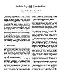
A typical TCP connection between an UE and a fix host via the radio interface of UMTS is shown in figure 1. The TCP congestion mechanisms have been originally developed for wired network with bit error rate (BER) less than 10-7. With this hypothesis, the primary cause of a packet loss is congestion.
PIMRC 2002
In wireless networks the packets losses are produced for other reason than congestion. The losses are mainly due to high bit error rates (as high as 10–3) and handoff procedures. In order to rapidly deal with erroneous blocks transmitted over the radio interface, there are defined specific mechanisms in a radio protocol stack : FEC (Forward Error Correction), ARQ (Automatic Repeat Request) or hybrid ARQ/FEC. For example, a simple RLC protocol in GPRS uses ARQ mechanism; ARQ is also utilised in a more enriched version of RLC in UMTS. Hybrid ARQ/FEC mechanism is definied in the RLC protocol of EGPRS.
IV.
Environment of simulation
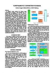
The simulation is realized on a RLC/TCP test-bed that has been developed at ENST. The simulated protocols stack is shown in figure 2. RNC + (SGSN and GGSN)
UE
RAN (RNC)
RLC
IP Network
Wireless Network
provides delivery of SDUs to higher layers in sequence (if the corresponding option is selected). A RLC entity delivers only SDUs, that are error free and ensures that a SDU is delivered only once. The acknowledged mode can be used for example for Internet browsing or email downloading. A comparison between the RLC and TCP protocols can be found in [5].
Wired Network
Figure 1. An TCP connection over RLC.
Server
Application
Application
TCP
TCP
IP
IP
Emulated PDCP
Emulated PDCP
RLC
RLC
Emulated MAC/PHY
Emulated MAC/PHY
IP
IP
any protocol
any protocol
384 kbps
III.
The radio protocol stack of UMTS
The radio interface of UMTS (interface Uu, [9]) is decomposed into three layers. The Physical layer (PHY) of UMTS offers transport services to MAC via radio transport channels. A radio transport channel is characterized by the size of block and by physical parameters. A radio frame period equal to 10 ms is consider at this level. A radio transport channel can use a small multiple of the radio frame duration to transmit data. The corresponding period is called TTI (Transmission Time Interval): TTI = 2i x 10 ms, where i ∈ {0, 1, 2, 3}. During TTI, several RLC blocks can be carried. The second layer (link layer) is split into two sublayers, MAC and RLC. The MAC layer offers services to the RLC layer via logical channels. The parameters associated with a logical channel depend on the type of transferred information (e. g., voice, video, radio control, and etc.). MAC layer schedules blocks from different logical channels according to physical constraints and required QoS parameters. A RLC entity segments RLC SDUs (Service Data Units) into Protocol Data Units (RLC PDUs or blocks). SDUs transport user data (e.g., a TCP segment via the Packet Data Convergence Protocol, PDCP). It also transports signaling messages, for instance from RRC layer (Radio Resource Control). The RLC protocol can operate in three modes: Transparent mode (Tr), Unacknowledged mode (UM) and Acknowledged mode (AM). The last mode is bi-directional, while the first two modes are unidirectional. The acknowledged mode, which is considered in this article, is the most elaborated mode. The mode guarantees delivery to the peer entity by using an ARQ mechanism. It
Figure 2. The simulated protocol stack. The PDCP, MAC and Physical layers are emulated in a simple way. In our analysis we consider a downlink data transmission (file transfer). The main parameters used during the simulations are given in table 2. The wireless round trip time, wrtt (i.e. rtt between UE and RNC entity, when no RLC retransmission occurs), is set to 60 ms. Table 1. Parameters during simulations. size of the transmitted file [Mbytes] radio frame duration [ms] TCP MSS [bytes] RLC block [bytes]
1 10 600 80
The TCP protocol use version Reno. The slow start threshold ssthresh is set to 32 MSS (Maximum TCP Segment Size). The maximum value of receiver’s window size rxwnd is 40 MSS. The RLC entity works in acknowledged mode. The transmitting RLC entity segments delivered SDUs from higher layers. If possible, the entity performs concatenation (i.e. a block may contain fragments of 2 SDUs). The receiving entity reassembles received blocks into SDUs and delivers them to the higher layer in sequence. A radio frame transmits up to six RLC blocks. The duration of a radio frame is 10 ms and TTI = 10 ms. The transmitting RLC
entity sets the Polling bit (bit P) in one of RLC blocks transmitted in each radio frame. The radio channel is dedicated to the TCP connection until the whole file is transferred. Handoffs are not considered. The error process on the radio channel is supposed to be memory less.
V.
Congestion and error notification
In order to provide feedback about the communication within IP network, there has been defined Internet Control Message Protocol (ICMP, [15]). One of the functions of ICMP is to report problems with delivery or handling of IP datagrams. For example, if a congestion occurs in IP network, a router that is overflowed may send to a source an ICMP message (Source Quench). Source Quench represents a request to decrease the traffic rate of data sent to Internet. On the Source Quench message, TCP has to react by slowing transmission on the connection. The recommended procedure in [7] is to trigger a slow start, as if retransmission timeout had occurred. ICMP messages use IP datagrams and therefore there is not any guarantee that sent messages reach their destination. Another way how to deal with congestion is mechanism ECN (Explicit Congestion Notification, [16]). Via this mechanism, TCP sender can be informed in advance about a possible congestion event and make necessary steps to avoid the congestion and a segment loss. In our model (figure 1), we consider that the TCP sender is not informed about the RLC buffer state. Neither ECN is used nor Source Quench message is sent to the TCP sender.
VI.
growths exponentially (phase SlSt in fig. 3). This is due to slow start phase in the TCP level. As soon as, TCP reaches ssthresh it changes to the congestion avoidance phase and the buffer occupancy starts to growth linearly (phase CgAv1 in fig.3).
Two factors that influence RLC buffer occupancy
In this section, we study RLC buffer occupancy for different values of mean wired Round Trip Time (RTTwired) and different block error rates (BlER) on the radio interface of UMTS. Delay in wired network Traces of RLC buffer occupancy for different mean RTTwired (50, 100 and 200 ms) are shown in figure 3. For the three RTTwired values, the standard deviation is set to 20 ms ([10]). The BlER on the radio interface is set to 10%. The RLC buffer is infinite and the maximum number of RLC block retransmissions is not limited. In our simulation scenarios, we introduce a congestion event in the wired network (denoted Er in the following). This is realized by introducing a single TCP segment loss with the same sequence number in all our simulation scenarios (the transmission always starts with the same sequence number). From figure 3, we can see that the RLC buffer occupancy reflects TCP mechanisms: slow start (SlSt) and congestion avoidance (CgAv). The buffer occupancy starts
Er SlSt CgAv1 CgAv2
CgAv`1
CgAv`2
Figure 3. Number of SDUs in the RLC buffer as function of time for different values of mean wired round trip time; BlER=10%. There is one TCP segment loss introduced in the wired network, (at time around 11s). As the txwnd reaches the maximum value (txwnd, defined as the minimum between the congestion window size cwnd and the advertised reception window size rxwnd), the txwnd stays constants. Likewise, the RLC buffer occupancy stops increasing linearly and oscillates around a mean value (phase CgAv2 in fig.3). For the round trip time 50 ms, it is value around 35 SDUs. The oscillations around the mean value are due to various numbers of RLC retransmissions for each SDU. The congestion event, introduced by a segment loss in the wired network (Er in fig. 3), can be observed at time 11s. TCP detects the congestion event by receiving three duplicated Acks. When receiving the third duplicated Ack, TCP retransmits the segment loss and reduce its congestion window by one half. Subsequently, the TCP sender enters into the fast recovery phase. During this phase, the TCP sender “inflates” its window by the number of DupAcks (duplicated Acks) it receives. Each received DupAck indicates that a segment has been removed from the network and is now cached at the receiver side. The sender waits until a certain number of DupAck are received without delivering to the RLC entity any segments. During this period, the buffer occupancy dramatically decreases because (i) there are no new delivered SDUs from TCP and (ii) the RLC entity continues to serve queued SDUs in the buffer. Once the TCP sender has received a fresh Ack, it exits the fast recovery phase and enters into the congestion avoidance phase. The buffer occupancy starts again to growth
linearly (phase CgAv1` in figure 3) till the txwnd reaches the maximum value (phase CgAv2` in figure 3). From the above graph, we can observe that for lower values of RTTwired the buffer occupancy is higher. Round trip time in the wired network influence also the radio transmission delay (figure 4). The radio transmission delay considered in this paper is calculated from the moment where a SDU is queued in RLC buffer till the moment where it is erased from the buffer (i.e. it has been correctly transfer and acknowledged). Since, there are more SDUs queued in the RLC buffer for low RTTwired delay, the radio transmission delay of each SDU is higher.
Figure 5. Number of SDUs in the RLC buffer as function of time for different BlER; mean RTTwired = 100 ms. As in figure 3, a TCP segment loss is introduced in the wired network.
Figure 4. Transmission delay over the radio interface for each SDU; BlER=10%. As in figure 3, a TCP segment loss is introduced in wired network. Block error rate In the last part of this section we investigate the impact of different BlERs (Block error rates) on the RLC buffer occupancy. The RTTwired is set to 100 ms and the standard deviation is set to 20 ms. As in the previous simulation scenario, we introduce a congestion event in the wired network (the lost segment has the same sequence number as in figure. 3). The curves of the RCL buffer occupancy for different BlERs (0%, 10% and 20%) are shown in figure 5. The buffer occupancy again reflects the divers TCP phases that have been discussed in the previous section. Different BlERs have different impact on the RLC level retransmission and thus on the global delay budget of TCP segments ([11]). Each SDU needs a different amount of RLC retransmission to be correctly transmitted over the radio interface. The radio transmission delay for each SDU is shown in figure 6. The higher BlER is, the longer time a correct transmission of a SDU over the radio interface takes. As we can see from figure 5 and figure 6, higher values of BlER mainly increase the radio transmission delay for each SDU than the buffer occupancy itself.
Figure 6. Transmisssion delay over the radio interface for each SDU; mean RTTwired = 100 ms. As in figure 3, a TCP segment loss is introduced in the wired network.
VII. Impact of RLC buffer size on TCP performance In the previous section we have analyzed factors that influence RLC buffer occupancy. In this section we examine the impact of RLC buffer sizes on the TCP performance. During the simulation, TCP segments are only lost due to the limited RLC buffer size. The buffer queues SDUs (TCP segments) arriving from TCP. If a TCP segment arrives when the buffer is full, the TCP segment is dropped. We considered that TCP is not informed about the RLC buffer state. Figure 7 shows evolution of TCP goodput versus block error rate (BlER) for different values of the RLC buffer size (the size is given in number of SDUs). Value of the goodput is normalized to the bandwidth of the wireless link, i.e. 384 kbps. The maximum number of RLC block retransmissions
is again not limited during the simulation. The mean RTTwired is set to 100 ms and the standard deviation is set to 20 ms. The upper bound for the goodput is lower than 1 due to protocol headers. In the first case (40 SDUs), the RLC buffer size is big enough so that there is no TCP segment dropped in the buffer during the file transfer. The TCP decreasing performance with higher BlER is mainly due to retransmission delay at RLC level. The second curve (30 SDUs) is for case where the RLC buffer size is not big enough to queue all arrived TCP segments during the file transfer. For low block error rates, the buffer is able to queued arrived SDUs. Nevertheless, for higher values of BlER, the buffer runs out of buffer space and starts occasionally drop SDUs. In the thrid case (20 SDUs), the RLC buffer size is so small that there are SDUs dropped even for very low BlERs. As BlER augments, there are more and more TCP segments dropped.
Figure 7. TCP goodput versus BlER: influence of RLC buffer size (40, 30 and 20 SDUs).
VIII. Conclusion In this paper, we have analyzed a downlink TCP connection via the radio interface of UMTS. We have studied two factors that impact the RLC buffer occupancy and we have shown impact of RLC buffer size on the TCP performance. When using TCP, RLC buffer occupancy reflects TCP congestion control mechanisms: slows start (exponential growth) and congestion avoidance (linear growth). Various wired round trip time and various block error rates influence RLC buffer occupancy. They increase the buffer occupancy and the transmission delay over the radio interface for each SDU. We have also examined the impact of RLC buffer size on the TCP performance. The presented simulations consider optimistic or simplified assumptions: a single TCP connection, low loaded cells, no handover, independent block errors, no specific constraints on reverse link. This simple context was useful to
calibrate our platform. More realistic conditions are under test. We presently investigate possible mechanisms that could prevent the overflow of RLC buffer, and the impact of link adaptation procedures on overall performance.
References [1] M. Allman, H. Balakrishnan, S. Floyd, “Enhancing TCP’s Loss Recovery Using Limited Transmit,” RFC3042, January 2001. [2] A. Bakre, B.R. Badrinath, “I-TCP:Indirect TCP for mobile hosts,” Int. Conf. Distributed Computing Syst. (ICDCS), May 1995. [3] H. Balakrishnan, V. Padmanabhan, S. Seshan, and R. H. Katz, “A comparison of mechanisms for improving TCP performance over wireless links,” ACM SIGCOM’96, August 1996. [4] H. Balakrishnan, S. Seshan, and R. H. Katz, “Improving reliable transport and handoff performance in cellular wireless networks,” ACM Wireless Networks, December 1995. [5] R. Bestak, P. Godlewski, P. Martins, “Interaction between the TCP and RLC protocols in UMTS,” Multiaccess, Mobility and Teletraffic for Wireless Communications, June 2002. [6] S. Biaz, N. H. Vaidya, “Distinguishing congestion losses from wireless transmission losses: a negative result,” Computer Communications and Networks, 1998. [7] R. Braden, “Requirements for Internet Host – Communication layers,” RFC-1122, 1989. [8] W. Ding and A. Jamalipour, “A new explicit loss notification with acknowledgment for wireless TCP,” Personal, Indoor and Mobile Radio Communications, September 2001. [9] H. Holma, A. Toskala, “WCDMA for UMTS, Radio Access for Third Generation Mobile Communications,” John Wiley & Sons,England 2000. [10] T. J. Kostats, M. S. Borella, I. Sidhu, G. M. Schuster, J. Grabiec, J. Mahler, “Real-time voice over packetswitched networks,” IEEE Network, Jan.-Feb. 1998. [11] F. Lefevre, G. Vivier, “Optimizing UMTS link layer parameters for a TCP connection,” Proc. IEEE Conf. on Vehicular Technology (VTC 2001 Spring), May 2001. [12] R. Ludwig, R. H. Katz, “The Eifel algorithm: Making TCP robust against spurious retransmission,” ACM Computer Communication Review, January 2000. [13] M. Mathis, J. Mahdavi, S. Floyd, and A. Romanow, “Selective acknowledgment options,”RFC-2018, 1996. [14] G.Montenegro, S. Dawkins, M. Kojo, V. Magret, N. Vaidya, “Long thin networks,” RFC-2757, 2000. [15] J. Postel, “Internet Control Message Protocol,” RFC792, 1981. [16] K. Ramakrishnan, S. Floyd, D. Black, “The Addition of Explicit Congestion Notification (ECN) to IP,” RFC-3168, September 2001.