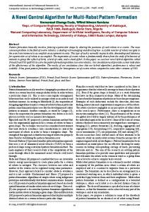
Robot Control through Brain-Computer Interface for Pattern Generation Paola Belluomo* Maide Bucolo † Luigi Fortuna ‡ Mattia Frasca §
University of Catania, Dipartimento di Ingegneria Elettrica, Elettronica e Informatica Viale A. Doria 6, 95125 Catania, Italy *
[email protected] †
[email protected] ‡
[email protected] §
[email protected] A brain-computer interface (BCI) system processes and translates neuronal signals, mainly from electroencephalogram (EEG) instruments, into commands for controlling electronic devices. This system can allow people with motor disabilities to control external devices through the real-time modulation of their brain waves. An EEG-based BCI system that allows creative luminous artistic representations is presented here. The system that has been designed and created in our laboratory combines the BCI2000 platform, which performs real-time analysis of EEG signals, with moving luminescent twin robots. Experiments are also presented.
1. Introduction
In the past few decades, analysis of the brain signals as a valid diagnostic approach in neurology has roused a growing interest. Some successful case studies for epilepsy as well as the diagnosis of coma, encephalopathy, and brain death are reported in [1]. In particular, in the 1980s the analysis of cerebral waves was used for the first time in a research context for the design of human machine interfaces (HMI). These include the brain-computer interface (BCI) [2] that provides a direct connection (through the analysis of brain signals acquired from multiple electrodes placed on the scalp) between the brain and an external device. A BCI can be defined as a communication system that does not depend on the normal output pathways of peripheral nerves and muscles [3]. The first implemented brain wave controlled tasks were spelling [4], allowing a subject to select letters of the alphabet, and cursor movement control [5]. More recently, a wide range of BCI applications have been designed to provide support for people with severe motor disabilities; examples include controlling a wheelchair on Complex Systems, 20 © 2012 Complex Systems Publications, Inc.
244
P. Belluomo, M. Bucolo, L. Fortuna, and M. Frasca
established paths using thought [6] and applications in home automation and domotics [7, 8]. In BCI systems, the brain signals are recorded, processed in real time, and translated into control commands that operate external devices or a computer display. Feature extraction and translation are processes that can be performed using different linear or nonlinear signals’ processing and classification methods [2, 9]. In addition, since the electroencephalogram (EEG) signals are unique for each subject, an adaptation algorithm is needed to optimize the performance of BCI processes in relation to each user. The most common electrophysiological measures involved in BCI are the event-related potential (ERP) and the sensory-motor rhythms (SMRs). The ERP are brain waves’ response to an external stimulus (visual, tactile, auditory, olfactory, or gustatory), while the SMRs are specific oscillations in the frequency range of 8 to 32 Hz that occur during motor tasks and even motor imagery [9]. Some laboratories have begun to develop BCI systems that provide people with severe motor impairment an alternative way to express their creativity, thus improving their quality of life. Kübler et al. [10], for example, developed a BCI application that allows screen painting using ERP. Another example that shows the possibility of creating recreational and therapeutic devices is proposed by Miranda et al. [11], who introduce an EEG-based BCI to compose and perform music. In this work, a creative BCI application based on SMR is presented. The proposed interactive BCI system allows communication between two coordinated robots and a user. The twin robots are equipped with light-emitting diodes (LEDs) so that the user can create a desired artistic representation by controlling their trajectories. The twin robots in motion generate luminous paths and a camera takes pictures of these light trajectories that represent the user’s “canvas.” The paper is organized as follows. In Section 2, the structure of the interactive platform designed is described. In Section 3, the control process is discussed. A gallery of pictures is shown in Section 4. Section 5 draws some concluding remarks.
2. Brain-Computer Interface-Based Interactive System
The BCI-based interactive system used in this work consists of an EEG system, a personal computer, twin robots, and a camera (Figure!1). The signals acquired through the EEG system are digitalized and elaborated through the BCI2000 platform running on a PC. During the signal processing procedure, a series of spatial and temporal filters are applied and specific features extracted from the EEG signals are translated into robot control commands. Afterward, the control signal is sent at the same time to two robots that will perform the Complex Systems, 20 © 2012 Complex Systems Publications, Inc.
Robot Control through Brain-Computer Interface for Pattern Generation
245
same movements and generate a luminous artistic pattern. Thus, the trajectories that the robots follow depend on the will of the user.
Figure 1. Block diagram of the designed interactive platform.
Figure 2 shows a general scheme of a BCI system. The brain signals are processed according to the particular cerebral waves that the system uses (SMR, ERP). A translation algorithm is necessary to convert the brain features extracted into control commands using linear or nonlinear equations. During this step, the adaptation of specific parameters is performed with relation to the output device that will be controlled. The BCI system has to provide feedback for the user, which can be visual, haptic, or auditory.
Figure 2. Block diagram of the BCI system.
The interactive BCI platform designed in this paper allows two coordinated robots and the user to communicate by modulation of the user’s SMRs. Our application has been tested exploiting the modules of the BCI2000 software [12], a general-purpose system for BCI. Complex Systems, 20 © 2012 Complex Systems Publications, Inc.
246
P. Belluomo, M. Bucolo, L. Fortuna, and M. Frasca
In the establishment of a BCI task, the training session has a fundamental role for two main reasons. First, it is essential for a subject to learn how to control the amplitude of his or her SMR by imagination or movement of the limbs or hands. Second, because the features of EEG signals differ from subject to subject, training is mandatory to determine the best channel location and most suitable frequency band (i.e., to determine which signals are the most suitable for the task and which frequency band is the most sensitive to changes). The designed technological platform consists also of two robots. The robots’ basic structure, shown in Figure 3, is the classic differential-drive, consisting of two actuated wheels and two smaller passive caster wheels whose function is to keep the robot statically balanced. The velocities of the two motors (MA and MB ) are indicated respectively as VM A and VM B . Each robot is equipped with an arm on which an electronic device to generate time-varying light patterns is mounted. The arm is actuated by a third motor, which turns faster than the other two motors. The electronic device mounted on the arm consists of an array of 16 red, green, and blue (RGB) LEDs and an autonomous microcontroller. Several parameters such as color, brightness, frequency, and intermittence of lights can be set, thus generating different luminous patterns. The kinematic structure of the robots was created using the LEGO MINDSTORMS robotic kit due to its simplicity and reconfigurability [13].
HaL
HbL
Figure 3. Structure of the robots: (a) side view and (b) front view.
3. Brain-Computer Interface Control Process
Real-time analysis of SMRs is at the basis of the communication between the user and the robots. The user, without any muscular involvement, modifies his or her neuronal activity in the primary sensory-motor areas by performing a motor imagery task. The task was performed by a healthy right-handed subject (female, aged 27 years) Complex Systems, 20 © 2012 Complex Systems Publications, Inc.
Robot Control through Brain-Computer Interface for Pattern Generation
247
p y y g j g y who wore an EEG cap with integrated electrodes. The EEG potentials were recorded at eight locations (F3, F4, T7, C3, Cz, C4, T8, and Pz) according to the International 10-20 System [14] and digitized at 2000 Hz. The locations of the EEG electrodes have been assembled over the motor and somatosensory areas. Movement and imagination of hand or arm movement cause a radial current flow in the sensory-motor area close to the positions C3 or C4, respectively associated with the right and the left arms [15]. During the training session, the total variance V of the brain signals was calculated for all eight channels in the 0 to 70 Hz frequency range. The variance was calculated according to the following expression: V!
1 n
‚ Hx - mL2 n
(1)
x!1
where x and m are the amplitude and the average value of the EEG signal for a specific channel and n is the number of samples (in our experiments, n ! 200). This measure provides a way to select the frequency band and locations where the EEG signals are more influenced by the task (left and right arm imagery). In fact, in Figure 4, the color maps of the variance related to training on the right (a) and left (b) arm movement for an imagery task show an increase of the variance value occurring for the motor imagery of the right arm on the electrode 4 (C3) around the frequency of 16 Hz, and for the motor imagery of the left arm on the electrode 6 (C4) around the frequency of 16 Hz. For this reason, the control law implemented has been based on information from such signals.
HaL
HbL
Figure 4. Variance values of the brain signals measured on eight channels:
(a)!while the subject thinks about moving the right arm and (b) while the subject thinks about moving the left arm.
Complex Systems, 20 © 2012 Complex Systems Publications, Inc.
248
P. Belluomo, M. Bucolo, L. Fortuna, and M. Frasca
The two EEG signals have been filtered and then translated into an output signal Cv using the equation Cv ! wr ÿ Ar + wl ÿ Al ,
(2)
where Ar and Al are the time-varying variances of one left-side (C3) and one right-side (C4) channel, respectively. The weights wr and wl are determined by the offline inspection of the brain waves according to the values of Ar and Al . Indeed for some subjects, the variances produced by imagining left and right movement have different intensity. If Ar > Al , it is convenient to set wl > wr and vice versa; if Al > Ar , it is convenient to set wr > wl . The command signal Cv is used both to control the robots’ movement and the position of a cursor on the video screen as visual feedback for the user. Concerning visual feedback, the screen displays a cursor on the left edge that begins to move horizontally toward the right edge of the screen. The cursor’s vertical position depends on the value of Cv that represents the angular coefficient of the tangent to the cursor trajectory. Concerning commands to robots, the BCI2000 processes in real time the brain signal measured on the user’s scalp and sends nine parameters to the MATLAB software. For our experiments only the value of Cv is used, but the system is general enough so that other parameters could be used for future applications. The User Datagram Protocol (UDP) has been used for communication between BCI2000 and MATLAB. The angular coefficient is converted in control signals for driving the robots using the following paradigm: † if Cv < - 1, the robots turn right quickly (VM A ! 80, VM B ! 0);
† if - 1 < Cv < 0, the robots turn right slowly (VM A ! 60, VM B ! 30); † if 0 < Cv < 1, the robots turn left slowly (VM A ! 30, VM B ! 60); † if Cv > 1, the robots turn left quickly (VM A ! 0, VM B ! 80).
4. Experimental Results
The robots can move in all directions within an arena 190 cm long and 245 cm wide. The scenario is totally dark. Initially, the light is turned off so that the spectator can see just the effects produced by the luminous pattern mounted on each robot. A camera is located in a strategic point to take pictures of the whole arena every 10, 15, or 20!seconds. The camera sends the pictures that it takes to a slide projector. The images produced can be used to provide feedback to the user. This visual feedback helps the user learn to control his or her EEG activity. The user controlling the robots, which when moving produce light patterns, can create a wide variety of images that are then taken by the camera. Indeed, every image generated in this manner is unique, Complex Systems, 20 © 2012 Complex Systems Publications, Inc.
Robot Control through Brain-Computer Interface for Pattern Generation
249
since several variables continually change. Examples of variables include the starting point of a robot with respect to the other; the intermittence and color of the luminous pattern; the presence of obstacles and the trajectory followed during the data capture process; and the exposure time of the camera lens. Some pictures of the trajectories observed during the motion of the twin robots are now reported. Figure 5 refers to the motion of the robots during a time interval of 10 seconds, while Figures 6 and 7 refer to an exposure time of the camera lens of 15 and 20 seconds, respectively. In particular, in Figure 7 we can clearly recognize the identical trajectories of the twin robots. A1 and A2 indicate the starting points of the two robots. In this case, the user has thought to move the right arm and consequently the robots turned right. Then, the user again imagined a right arm movement and another change of direction (points B1 and B2) was observed in the robot trajectory. The points where the robots stopped their motion are C1 and C2.
Figure 5. Picture obtained by the user controlling the two robots modulating
her brain signals. The time exposure of the camera lens is 10 seconds.
Figure 6. Picture obtained by the user controlling the two robots modulating
her brain signals. The time exposure of the camera lens is 15 seconds.
Complex Systems, 20 © 2012 Complex Systems Publications, Inc.
250
P. Belluomo, M. Bucolo, L. Fortuna, and M. Frasca
Figure 7. Picture obtained by the user controlling the two robots modulating
her brain signals. The time exposure of the camera lens is 20 seconds.
5. Concluding Remarks
An interactive brain-computer interface (BCI) system has been designed to provide a more accessible form of communication for those individuals who have severe motor disabilities. Our work permits creativity to be expressed by the generation of artistic images. A subject modulates his or her sensory motor rhythms (SMRs) with the aim of creating artistic representations by controlling the motion of two moving robots. For future application, the user could also control the third motor of the robots by using other EEG features, for instance the time-varying amplitude produced by the imaginary movement of the feet and/or of both hands. Moreover, different brain waves, like the event-related potential (ERP), could be translated into control commands, allowing the subject to communicate with the robots.
References [1] B. Abou-Khalil and K. E. Musilus, Atlas of EEG and Seizure Semiology, Maryland Heights, MO: Butterworth-Heinemann (Elsevier), 2006. [2] J. R. Wolpaw, N. Birbaumer, W. J. Heetderks, et al., “Brain-Computer Interface Technology: A Review of the First International Meeting,” IEEE Transactions on Rehabilitation Engineering, 8(2), 2000 pp. 164– 173. doi:10.1109/TRE.2000.847807. [3] J. R. Wolpaw, N. Birbaumer, D. J. McFarland, et al., “Brain-Computer Interfaces for Communication and Control,” Clinical Neurophysiology, 113(6), 2002 pp. 767–791. [4] K. Smith, “Brain Implant Allows Mute Man to Speak,” Nature, 2008. doi:10.1038/news.2008.1247. [5] J. R. Wolpaw, D. J. McFarland, and T. M. Vaughan, “Brain-Computer Interface Research at the Wadsworth Center,” IEEE Transactions on Rehabilitation Engineering, 8(2), 2000 pp. 222–226. doi:10.1109/86.847823.
Complex Systems, 20 © 2012 Complex Systems Publications, Inc.
Robot Control through Brain-Computer Interface for Pattern Generation
251
[6] B. Rebsamen, E. Burdet, C. Guan, et al., “Controlling a Wheelchair Indoors Using Thought,” IEEE Intelligent Systems, 22(2), 2007 pp. 18–24. doi:10.1109/MIS.2007.26. [7] J. del R. Millàn, F. Renkens, J. Mourino, et al., “Noninvasive BrainActuated Control of a Mobile Robot by Human EEG,” IEEE Transactions on Biomedical Engineering, 51(6), 2004 pp. 1026–1033. doi:10.1109/TBME.2004.827086. [8] F. Babiloni, F. Cincotti, M. Marciani, et al., “The Estimation of Cortical Activity for Brain-Computer Interface: Applications in a Domotic Context,” Computational Intelligence and Neuroscience, 2007, 2007. doi:10.1155/2007/91651. [9] J. R. Wolpaw and D. J. McFarland, “Control of a Two-Dimensional Movement Signal by a Noninvasive Brain-Computer Interface in Humans,” Proceedings of the National Academy of Sciences of the United States of America, 101(51), 2004 pp. 17849–17854. doi:10.1073/pnas.0403504101. [10] A. Kübler, A. Furdea, S. Halder, and A. Hösle, “Brain Painting—BCI Meets Art,” in Proceedings of the 4th International Brain-Computer Interface Workshop and Training Course, Graz, Austria, 2008 pp.!361–366. [11] E. R. Miranda, “Brain-Computer Music Interface for Composition and Performance,” International Journal on Disability and Human Development, 5(2), 2006 pp. 61–67. [12] G. Schalk, D. J. McFarland, T. Hinterberger, et al., “BCI2000: A General-Purpose Brain-Computer Interface (BCI) System,” IEEE Transactions on Biomedical Engineering, 51(6), 2004 pp. 1034–1043. doi:10.1109/TBME.2004.827072. [13] M. Gasperi, P. Hurbain, and I. Hurbain, Extreme NXT: Extending the LEGO MINDSTORMS NXT to the Next Level, Berkeley, CA: Apress, 2007. [14] C. D. Binnie, E. Dekker, A. Smit, et al., “Practical Consideration in the Positioning of EEG Electrodes,” Electroencephalography and Clinical Neurophysiology, 53(4) 1982 pp. 453–458. doi:10.1016/0013-4694(82)90010-4. [15] R. Neshige, H. Lüders, and H. Shibasaki, “Recording of MovementRelated Potentials from Scalp and Cortex in Man,” Brain, 111, 1988 pp.!719–736. [16] P. Belluomo, C. Camerano, L. Fortuna, and M. Frasca, “From Kinetic Art to Immaterial Art through Chaotic Synchronization,” International Journal of Bifurcation and Chaos, 20(10), 2010 pp. 3379–3390. doi:10.1142/S0218127410027787. [17] A. Buscarino, C. Camerano, L. Fortuna, et al., “Chaotic Mimic Robots,” Philosophical Transactions of the Royal Society A, 368(1918), 2010 pp. 2179–2187. doi:10.1098/rsta.2010.0028.
Complex Systems, 20 © 2012 Complex Systems Publications, Inc.