and sometimes of teammates, by just observing the other play- ers' attitude and ... obstruct its trajectory, and 2) a player can know where the ball is by looking in ...
Robot Detection System in the Soccer Domain BY J. RUIZ-DEL-SOLAR, R. VERSCHAE, M. ARENAS, AND P. LONCOMILLA
T
he automatic detection and identification of robots, as well as the recognition of their behavioral patterns, is of increasing importance in multirobot scenarios. Multirobot systems are becoming relevant as a result of the increasing number of industrial, service, and exploration robots in current use. Thus, collaborative robot behaviors will be of high importance in scientific and industrial application areas such as ground, space, and underwater exploration; entertainment; surveillance; human assistance; manipulation and assembly of objects in industrial environments; and autonomous rescue operations. In addition, individual robots (robots not belonging to a given team) will need to interact and, in some cases, collaborate with other robots while performing different tasks in a common environment, more and more frequently. Depending on the specific situation, robots will develop different kinds of relationships as humans do. In many cases, robots will cooperate, but in other cases, they will just observe each other, ignore each other, or even compete with each other. We can illustrate these ideas through the following futuristic scenario: a shopping center where several kinds of service robots interact with humans. In such a scenario, robots assume different specific tasks such as cleaning the floor, restocking shelves and arranging items, purchasing items, assisting humans, and even selling items. Cooperation and interaction to some degree will be required even when these different robots have not met before or in the case they do not share a common protocol of data communication. There is a complex variety of interactions that will arise among these different robots as well as between them and humans. One of the basic skills that robots will require in scenarios such as the one described earlier is robust visual interaction Digital Object Identifier 10.1109/MRA.2010.938840
DECEMBER 2010
© LUSHPIX, OJO IMAGES, INGRAM PUBLISHING
with the environment, which includes the detection and identification of other robots and their behaviors. Conversely, surveillance and/or augmented reality systems operating in the same scenarios will require detecting and identifying robots, as well as their behaviors. Given the above, it is highly relevant to develop automatic, fast, and accurate methods for the detection and identification of robots, as well as the determination of their behaviors. However, the development of such methods is a complex task because of the changing conditions of real-world scenarios (e.g., variable illumination and/or cluttered backgrounds), as well as the varying appearance of the robots that depends on their relative position in relation to the camera, which is especially important in the case of humanoids and other legged robots. An additional challenge to be taken into account is the current limited processing power of most service robots, which imposes some restrictions on the methodologies that can be used to solve these problems. In the last decade, the use of cascades of boosted statistical classifiers [1]–[4] has arisen as a very interesting methodology for the fast and accurate detection of human faces, human beings, cars, etc. This methodology has recently been extended to the resolution of multiclass problems [5], [6], which permits the simultaneous detection of objects belonging to different classes [5]–[7], and the detection of objects under different views [8]. It seems a very promising idea to extend the use of this
1070-9932/10/$26.00ª2010 IEEE
IEEE Robotics & Automation Magazine
43
methodology to the multiview and multiclass detection of robots. In addition to obtaining fast and accurate robot detectors, the use of this methodology allows the development of multiclass detection systems for the simultaneous detection of robots and humans, as well as other objects of interest. In previous work, we have used multiple cascades of boosted statistical classifiers, running in parallel, for the detection of robots under different views (one cascade for each object view) [9]. In this work, we extend this idea presenting, for the first time, the multiview and multiclass detection of robots using trees of cascades of boosted statistical classifiers. In the framework, a single classification tree allows the detection of robots under different views and/or the simultaneous detection of robots belonging to different classes (robot identification). The determination of robot behaviors can also be addressed using similar methodologies to the ones already developed for the analysis of human behaviors. As a first step in this direction, we are interested in the determination of the gaze direction in humanoid and legged robots. One of the main reasons for this approach is the fact that gaze-direction determination is a powerful anticipatory perceptual mechanism for determining the next action of other individuals. For instance, in robot soccer, similarly as in the case of human soccer, good players should have the ability to anticipate the actions of opponents, and sometimes of teammates, by just observing the other players’ attitude and pose. Gaze direction determination is one possible mechanism to accomplish this, which can be illustrated using the following two situations: 1) an attacker player can determine if an opponent is observing it or not, and then plan its next actions to avoid the opponent’s approaches or obstruct its trajectory, and 2) a player can know where the ball is by looking in the same direction where an opponent is looking (assuming the opponent knows the ball’s location). The determination of gaze direction in robots is a difficult task because it requires the accurate determination of the robot’s head pose. We have developed a gaze-direction determination system that is based on the use of a set of prototype head images acquired under different view angles, which define a three-dimensional (3-D) model of the head, and a matching procedure between these prototypes and the image under analysis, which allows selecting the most similar prototype and an affine transformation that relates the prototype with a given image’s area. This transformation permits determining the robot’s head position and orientation in the image domain. Afterwards, the direction of gaze is determined by a composed coordinate transformation that considers the 3-D pose of the observing camera and the relative pose of the observed robot’s head. This relative pose is computed using the parameters of the affine transformation, the view angles of the most similar prototype, and the intrinsic parameters of the observing camera. The matching methodology, implemented by using an improved version of Lowe’s scale invariant feature transform (SIFT)-recognition paradigm [10], is the key element in the gaze-direction determination system. To the best of our knowledge, no other groups have proposed alternative methods to solve this important problem. 44
IEEE Robotics & Automation Magazine
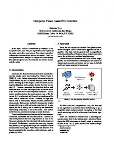
The robot detection system and the gaze-direction determination system are designed to work together. After the robots are detected, the gaze-direction determination system determines the robot’s head pose and its gaze direction (see Figure 1). Additionally, because of its wider applicability, the robot detection system can be used independently of the gazedirection determination system. In this article, we describe both systems and present real applications of the robot detection system in the robot soccer domain.
Fast and Accurate Multiclass Robot Detection Using Boosted Classifiers Following the so-called sliding-window approach, the proposed multiclass robot detection system performs an exhaustive search over different positions and scales by analyzing and classifying patches of the image (see block diagram in Figure 2). The system works as follows: To detect robots at different scales, the input image is iteratively downsized, obtaining a pyramid of images representing the input image at different resolutions (multiresolution analysis module). In the window extraction module, windows of a fixed size (e.g., 24 3 24 pixels) are extracted from each scaled version of the input image. The window’s size defines the smallest size of robots that can be detected. Then, each window is analyzed by a boosted classifier (H(x)) that predicts if it corresponds to a robot window or to a nonrobot window. After all considered windows have been processed and classified, in the overlapping detection processing module, the size and position of the final detections are determined. In the detection system, the key element to obtain fast and accurate detections is the classification module. We will present the classification approach being used, and some important issues related to the training of the classifiers.
Boosted Cascade Two-Class Classification Cascade classification started with the seminal work of Viola and Jones [1]. Under this paradigm, fast classifiers/detectors that able to achieve high-detection rates are obtained by taking advantage of the natural asymmetry of the two-classification problem: in the images under analysis most windows (image patches) to be analyzed correspond to nonobject windows (background). Thus, to achieve an efficient classification/detection, less time should be spent on nonobject windows than on object windows. Hence, fast classification is achieved by using classifiers that make the decision about whether the windows correspond to the object or not, by performing a sequence of questions (verification stages) of increasing computational complexity, i.e., the first questions require less processing time than the later ones. In this way, windows that can easily be classified as nonobject are discarded at the first stages (first questions), while objectlike windows are analyzed by several stages. Hence, the average processing time of a window is almost completely defined by the processing time of the nonobject windows. Within the cascade structure, the window’s classification is carried out using boosted classifiers. Boosted classification is based on the idea of training the same classifier several times, each time on a different training DECEMBER 2010
(a)
(b) (c)
(e) (d)
Figure 1. Example of the gaze-direction determination in a humanoid robot. (a) Detected robot. (b) Local interest points and descriptors. (c) Correspondences between the segmented robot’s descriptors and the head prototypes. (d) Segmented robot and the most similar prototype. (e) The 3-D pose of the robot’s head relative to the observer (in red) and the line of gaze (in blue).
set or on a different distribution of the training set. Each of the obtained classifiers (called weak classifiers) is then used to obtain the final classifier (called robust classifier). Real Adaboost [11], which has been widely used in different kinds of classification problems because of its simplicity, high performance, and high training speed, is one of the most popular boosting algorithms. P Adaboost builds an additive model of the form H(x) ¼ Tt¼1 ^ht (x), by iteratively incorporating weak classifiers ^ht (x) to the sum, to minimize an upper bound of the training error. In a boosted cascade classifier, the additive model allows controlling the computational complexity of each stage by selecting the number of terms (T ) and the complexity of the weak classifiers. In [1], a particular feature ft (x) 2 F is associated with each weak classifier: ^ht (x) ¼ ht (ft (x)), with ht (x) 2 H. Popular sets of features F include Haar-like wavelets [1] that can be evaluated very efficiently using the so-called integral image (see Figure 3), and modified local binary patterns [3] that encode local gradient information efficiently. In Figure 3(a), integral image representation: ii(x, y) represents the sum DECEMBER 2010
of all pixels’ intensities up to the top-left of the image. In Figure 3(b), region A of an image can be calculated in constant time using four values (L4 þ L1 � (L2 þ L3)), thanks to the integral image representation. In (c), family of features used by Viola and Jones [1] is shown. In Figure 3(d) and (e), examples of how these features can be used to detect robots. The features and their associated weak classifiers are automatically selected during training. Examples of other features include Edgelets [8], granular features [5], and object-part correlation [7]. It is important to note that all these features work in grayscale images allowing the detection of the objects under variable illumination conditions. Regarding the weak classifiers, ht , families of functions H that have been used include decision stumps (with binary [1] and real outputs [7]), domain partitioning classifiers [2], [8], [3], and classification and regression tree (CART) classifiers [4]. A key element for obtaining high-performance cascade classifiers is the use of appropriate training procedures. In terms of the selection of training examples, the common procedure for selecting the negative examples is to apply the so-called bootstrap procedure [12]. This procedure consists of retraining IEEE Robotics & Automation Magazine
45
… V1 Multiresolution Analysis
Input Images
H(x) Classifier Object (Robot)
Processing of Overlaying Windows
Multiresolution Images
Window Extraction
…
Vn
Windows to Process
Robot Detection and Classification
Nonobject
Figure 2. Block diagram of the robot detection system.
x
x
y
y
L1
L2 A
ii (x, y)
L3
(a)
L4
(b)
a classifier by enlarging the set of negative examples with new patterns that are being misclassified. This procedure is applied several times to obtain a good representation of (the boundary of) the negative class. In [3], intra- and interlayer bootstrap procedures were used in the training of nested cascades, improving the final classification results. Another important issue to be resolved during training is the definition of the structure and complexity of classifiers. In [3], a procedure that allows the automatic selection of the number of weak classifiers at each layer of the cascade using a criterion that seeks to obtain an optimal cascade classifier in terms of processing time, false-positive rate (FPR), and true-positive rate is presented. Using the described techniques, we have been able to build, in addition to face, eyes and car detectors [3], [6], singleview robot detectors [9]. The use of several of these detectors in parallel allows obtaining multiview and multiclass detections at the expense of increasing the detection time.
Boosted Cascade Multiclass Classification (c)
(d)
(e)
Figure 3. Example of the use of rectangular (Haar-like) features. 46
IEEE Robotics & Automation Magazine
The concept of nested boosted cascade classifiers is extended to the multiclass case by including concepts such as vector-boosted classifiers, feature sharing, coupled classifiers, and coarse-to-fine (CTF) classification. All these concepts are integrated in the development of two multiclass classifiers: multiclass boosted cascade classifiers, and trees of multiclass boosted cascade classifiers [trees of cascades classifiers (TCAS)] [6]. Following [5], the multiclass classifier used at each layer ~k�1 (x)þ ~k (x) ¼ H of nested cascade has a vector form H PTthe k ~ t¼1 ht, k (ft, k (x)), where, in the simplest case, each component can represent a class or an object’s view. The training of each layer is performed using the algorithm introduced in [5]. The basic idea behind this algorithm is to assign to each training DECEMBER 2010
nonzero components of ~ Ak (x) need to be evaluated at layer k. These nonzero components represent a subset of classes with positive output at the current layer (and potentially a positive output in the cascade). In this way, as a sample moves through the cascade, the output goes from a coarse output in the object space, to a finer one, which complements the CTF search on the nonobject space given by the cascade structure. The concept of multiclass cascade classifiers is extended by defining a nested TCAS classifier, which allows obtaining computationally efficient classifiers, as well as the capability of classifying very different objects using a single classifier [6]. A TCAS classifier corresponds to a directed tree, with each node having a variable number of siblings. A node, N, has nN sib~N lings, fNs gs¼1,..., nN , and consists of a multiclass classifier H (in our case a multiclass CTF-nested cascade) and a mask ~ AN 2 f0, 1gM . Each node has a nested structure, i.e., its output depends on the output of its ancestors and is defined as: ~N (x), with H ~pN (x) the output of ~ (x) ¼ H ~pN (x) � ~ AN (x) þ H H the ancestor of N (if the ancestor is the root of the tree, then ~pN (x) ¼ ~ 0). It is important to note that only nonzero compoH ~N , i.e., the CTF evaluanents of ~ AN need to be evaluated in H tion in the object target space is also used here, which allows maintaining an efficient evaluation. ~ AN indicates which components/classes of the classifier are considered at the current node. Thanks to this, all nodes of the tree have an output with the same number of components, but, at each node, only a subset of the components is active (see an example in Figure 4). In the example, the tree consists of five nodes. Each node has a CTF multiclass cascade with a variable number of layers (from three to six in this example). During the evaluation of the tree, for a particular window being classified, dashed circles indicate layers not being evaluated and dashed lines indicate inactive components. However, in regard to this, one
Object A
example xi an objective region in a vector space. The objective region is defined as the intersection of subspaces (e.g., a set of half spaces), with each subspace defined by some parameters (e.g., a vector~ a) and with a set of regions defined by a set R of parameters. In this setting, a sample, x, belonging to class Y , and represented by a� parameter � � set, R, is classified correctly if ~ (x) � 0. For simplicity, we take M , and only if 8~ a 2 R, ~ a �H the dimension of the vectors ~ a, as the number of object classes ~ (x) : RP �! RM , with P the we want to detect. Therefore, H number of pixels of an image window. To determine if class Y is � be �assigned to an input x, it is necessary to test whether � to ~ (x) is positive for all vectors ~ ~ a �H a 2 R, i.e., for all vectors associated to class Y . Note that, to speed up the classification process and to simplify the learning process, all components share feature evaluations. This is a key point to gain on processing time, and as shown in [7] and [13], the sharing of features and weak classifier parameters allows reducing considerably the processing time when using a multiclass classifier. In terms of multiclass weak classifiers, the components of ~ ht (ft (x)), i.e., the scalar classifiers, can be chosen to be dependent or independent of each other (see [13] for a definition of independent, joint, and coupled classifiers). Another important element is to perform a CTF search in the object target space. To achieve this, the output of layer k in ~k�1 (x)þ ~k (x) ¼ (H aPCTF multiclass cascade is defined as H Tk ~ ~ ~ ~ ~ ~ t¼1 ht, k (ft, k (x))) � Ak�1 (x), with H0 (x) ¼ 0, A0 (x) ¼ 1, and ~ � the point-wise product between two vectors. Qk�1Ak ðxÞ is defined componentwise by: A0 (x, m) ¼ u(H(x, m)) i¼0 Ai (x, m), with u() the unit step. The use of ~ Ak (x) can be interpreted as verifying the condition of the input belonging to a particular class at each layer of the cascade, in a per class manner, only for the subset of hypotheses that was already positively verified at the ~k (x), only previous layers. One important thing is that, in H
Nonobject
Nonobject
Nonobject
Nonobject
Nonobject
Nonobject
Nonobject
Object C
Nonobject
Nonobject
Nonobject
Object B
Nonobject
Nonobject
Nonobject
Nonobject
Nonobject
Nonobject
Nonobject
Nonobject
Figure 4. Example of a multiclass TCAS for a three-class detection problem. The nested structure of the classifier is not represented in this figure .
DECEMBER 2010
IEEE Robotics & Automation Magazine
47
(d)
(b)
(e)
Multiview (Frontal, Lateral Back) Aibo Detection
100 90 80 70 60 50 40 30 20 10 0
Detection Rate
Detection Rate
(a)
Three Parallel Cascades Three-Classes TCAS 0
0.02 0.04 0.06 0.08 Number of False Detections (Image) (c)
0.1
Humanoid (Hajime) Detection
100 90 80 70 60 50 40 30 20 10 0
One Parallel Cascades Four-Classes TCAS 0
0.02 0.04 0.06 0.08 Number of False Detections (Image) (f)
0.1
Figure 5. (a) and (b) Examples of detection of lateral and back AIBO. (c) ROC curves of multiview (frontal, lateral, and back) AIBO detection, (d) and (e) Examples of detection of humanoid robots. (f) ROC curves of humanoid (Hajime) detection.
PN important restriction is made: ~ AN ¼ ns¼1 As , which means that the (binary) mask for any two siblings of node N, Ni , and Nj , with i 6¼ j, holds that ~ Ai � ~ Aj ¼ ~ 0. This restriction allows simplifying the evaluation of the tree by allowing an efficient recursive implementation. It also simplifies the training process (see [6]), because two nodes that are in different branches of the tree do not depend on each other. Given that the output of all nodes have the same dimension and thanks to the structure of the tree, the output of a TCAS can be defined as the ~ sum Pnleafsof the output of all its leafs N(i), ..., N(nleafs ) : HT (x) ¼ ~ j¼1 H(j) (x) [6]. We have successfully used TCAS classifiers in the multiview detection of human faces [6], in which we have determined that the processing time of the classification increases logarithmically with the number of classes (views), in 48
IEEE Robotics & Automation Magazine
comparison with the linear increase in the case of using multiple parallel cascades.
Robot Classification Results The proposed classifiers are evaluated in two different problems, multiview and multiclass robot detection. In the multiview detection problem, SONY artificial Intelligence robot (AIBO) ERS7 robots are detected under three different views, by defining the following classes: frontal, lateral, and back. The multiclass detection problem includes the multiview detection of AIBO robots plus the single-view detection of Hajime HR18 humanoid robots (see robot pictures in Figures 5 and 6). Altogether, four classes are defined (three associated with AIBO robots and one with Hajime robots). To solve these DECEMBER 2010
problems, we have built four single-class cascade detectors for each of the four classes (humanoids, frontal AIBO, lateral AIBO, and back AIBO), a three-class TCAS classifier that is used to detect the AIBOs under the three views, and a four-class TCAS classifier that solves the defined multiclass robot detection problem. The classifiers are evaluated using the UchileAiboDB [9], which consists of 724 images of 208 3 160 pixels containing 1,017 AIBO robots under the three defined views, and using the UchileHumanoidDB [9], which consists of 244 images of 640 3 480 pixels containing 493 Hajime humanoid robots. Figure 5(a) and (b) presents detection results obtained using the three-class TCAS classifier in the multiview AIBO detection problem. Receiver operating characteristic (ROC) curves (detection rates versus number of false detections) for the threeclass TCAS classifier and the parallel cascades used to detect frontal AIBO, lateral AIBO, and back AIBO are presented in Figure 5(c). Table 1 presents the corresponding processing times. As can be observed in Figure 5(c), the use of parallel cascades has lower performance compared with the use of a three-class TCAS classifier, but the difference is small, with the three-class TCAS classifier having up to 1% higher detection rates for any given number of false negatives. More importantly, as shown in Table 1, the TCAS classifier is 1.6 times faster than using the three single-class cascades in parallel. In [6], we obtained similar results in a multiview face detection problem, in which the TCAS was evaluated using up to 20 different views (faces rotated under different roll angles). Figure 5(d) and (e) shows detection results obtained using the four-class TCAS classifier in the detection of Hajime humanoids. Figure 5(f) presents ROC curves when the four-class TCAS classifier and a single-class cascade classifier are just used for the detection of Hajime robots. The corresponding processing times are presented in Table 2. In addition, in Table 2, the processing time of the four-class TCAS classifier used to detect all four classes, and the use of four single-class cascade classifiers, are presented. In Figure 5(f) it can be observed that the four-class TCAS classifier used to detect Hajime humanoids has a clearly better performance than the use of a cascade trained to detect just that particular class, with a gain of up to 17% points for 0 false positives. In addition, Table 2 shows that the processing speed of both classifiers is very similar, with the TCAS classifier being slightly slower when compared with a single-class cascade. More importantly, when the four-class TCAS classifier is used to detect humanoids, frontal AIBOs, lateral AIBOs, and back AIBOs, its processing speed is two times faster than the one employed by four single-class cascades performing the same tasks. These results show that the accuracy of the TCAS classifier is comparable or better than that of parallel cascade classifiers; for any given number of false positives, the detection rate of the TCAS classifier is larger. In addition, using the TCAS classifier is much faster than the use of cascades in parallel. We have observed this same behavior, and with more classes, in other detection problems [6].
Gaze-Direction Determination Using Visual Matching The line of gaze of an observed robot is computed using the pose of the observing camera in global coordinates, and the DECEMBER 2010
(a)
(b)
(c)
Figure 6. Examples of the SIFT-based matching results for the case of three different legged platforms: SONY AIBO ERS7, Hajime HR18 humanoid, and ALDEBRAN NAO humanoid.
Table 1. Multiview detection problem. Processing Database Time (s)
Classifier
Target Views
Three-class TCAS Three parallel cascades
Frontal, lateral, 0.079 and back Frontal, lateral, 0.126 and back
UchileAiboDB UchileAiboDB
Processing times on the UchileAibo DB (208 3 160, 724 images).
relative pose, with respect to the observer, of the observed robot’s head and its camera. In the described system, we assume the robot does not have the ability of moving its camera independently of its head. Therefore, the relative pose of the camera IEEE Robotics & Automation Magazine
49
results (affine transformation) for the case of three different legged platforms are shown in Figure 6. The colored lines in this figure Processing indicate the final SIFT-matches used to comClassifier Target Classes Time (s) Database pute the affine transformation. The condition Four-class TCAS Humanoids 0.464 UchileHumanoidDB for successful matching is that the head’s One-class cascade Humanoids 0.411 UchileHumanoidDB image allows obtaining several repeatable Four-class TCAS AIBOs (3 views) and 0.870 UchileHumanoidDB local descriptors. humanoids Local descriptors computation and Four Parallel cascades AIBOs (3 views) and 1.767 UchileHumanoidDB matching is implemented using a SIFThumanoids based object recognition system, which has Processing times on the UchileHumanoid DB (640 3 480, 244 images). been designed to achieve robust operation in dynamic environments [14]. Naturally, is fixed to the head’s pose. A 3-D model of the robot’s head is other approaches can be used to implement the 3-D head built using a set of prototype head images acquired under differ- model and to compute the affine transformation. ent view angles (see example in Figure 7). The origin and length The implemented system works as follows: A reference system of each arrow in Figure 7 indicate the position and scale of the fixed to the observed head, with its X-axis aligned with the local interest point. The arrow’s orientation is given by the main camera axis (in the observed head) and its origin in the observed orientation of the associated SIFT descriptor, which encodes camera frame, is defined (see Figure 8). In this reference system, information of the local gradients. the line of gaze intersects the floor at a position ð k 0 0 ÞT . In a A match between local descriptors belonging to the robot’s global reference system, this 3-D position has coordinates image and the set of prototypes is used to select the most simi- ð x0 y0 z0 ÞT . Considering that a composed coordinate lar one. This matching process also allows calculating the affine transformation M (homogeneous matrix) relates both reference transformation that relates the image’s area containing the systems, the gaze coordinates on the floor are obtained by solving: robot’s head with the most similar prototype [see example in ð x0 y0 z0 ÞT ¼ M ð k 0 0 ÞT ; z0 ¼ 0 ðat floorÞ; ð1Þ Figure 1(c) and (d)]. In Figure 1(a), the observed humanoid robot is segmented from the original image using the nested cascade detector. In (b), local interest points and descriptors are where M is a composition of the following three homogeneous calculated in the segmented robot. In (c), correspondences transformations (M ¼ M1 M2 M3 ); M1 is a homogenous matrix (matches) between the descriptors belonging to the segmented that defines the pose of the observing camera in global coordirobot and the head prototypes are computed. In (d), the affine nates; M2 is a homogenous matrix that defines the relative pose of transformation that relates the segmented robot and the most the observed camera with respect to the observing camera, withsimilar prototype is computed. It allows detecting the robot’s out considering rotations of the observed head; M3 is a homogehead. In (e), the 3-D pose of the robot’s head relative to the nous matrix that considers rotations of the observed head. The global pose of the observing camera (M1 ) can be observer (in red) and the line of gaze (in blue) are calculated. Finally, the relative pose of the observed robot’s head is known a priori, in case the camera is fixed, or it can be comobtained by using the affine transformation parameters, the puted by the observer itself (a robot or a surveillance system) prototype view angles, and the intrinsic parameters of the using encoders and other sensor data. M2 is computed by using observing camera. Some examples of the SIFT-based matching the intrinsic parameters of the observing camera and the coordinates of the observed head in the image plane, which are obtained after computing the affine transformation (see [14] for details). Finally, M3 is obtained using the view angles of the most similar prototype, which are fixed and known a priori. Figure 8 illustrates these transformation matrices, in the case of a NAO humanoid robot being observed by NAO robot. The affine transformation is computed using the SIFT-based L&R method [14]. This method uses sDoG þ Hessian interest points (local maxima/minima in the scale-space image set) [10] and SIFT descriptors of the gradient distribution in the region around each interest point [10] for creating correspondences between the images under analysis and the database images. Then, affine transformations are detected using a Hough transform over the similarity-transformation parameters’ space [10], and the following verification stages are used to reject incorrect transformations: a fast probabilistic hypothesis rejection test to reject Hough cells with a low probability of containing a correct Figure 7. Humanoid robot-head prototypes and their local interest points. transformation [15], a linear correlation verification stage to Table 2. Multiclass detection problem.
50
IEEE Robotics & Automation Magazine
DECEMBER 2010
reject transformations that can be numerically unstable [14], a geometrical distortion verification stage to reject transformations that involve strong distortions [14], a pixel correlation verification stage to reject transformations that map wrong image areas [14], and the random sample consensus (RANSAC) algorithm [16] and a semilocal constraints test [17] to refine the final affine transformation. In [14], it is shown that the use of these verification stages allows largely reducing the number of false positive detections (from approximately 80% to 3% in a database of 100 real-world images), while slightly increasing the detection rate and the processing speed. The gaze-direction determination system has been validated using SONY AIBO ERS7 and Hajime HR18 robots (see Figure 6). In both cases, prototype images in which only the yaw angle is determined were considered (see Figure 7). In the experiments, the observed robot stands in a RoboCup soccer field of 600 3 400 cm, and the gaze point at the floor is estimated and measured. A variable number of experiments is carried out (8/28 in the ERS7/HR18 case). In each case, the observed robot is looking at different positions on the field. A mean error of 14.7/34.1 cm between the predicted and real gaze point at the field with a standard deviation of 9.4/24.2 cm was obtained for the ERS7/HR18 robots. From the observer robot viewpoint, the angular error between predicted and real gaze points has a mean of 31.7/13.6° with a standard deviation of 9.6/14.5°. These results are very good because, from the observer point of view, they allow largely reducing the estimation of the field region on which an observed robot is putting its attention. The estimation errors are due to the use of prototype images with variations only on the yaw axis, and a nonaccurate estimation of the pose of the observing camera. (In legged robots the encoder and accelerometer data is noisy.)
Applications in Robotic Soccer The robot detection system has been applied in robotic soccer setups. It has been used in soccer players for the detection of other robots while playing and in a robot referee as part of the object recognition tool that allows detection and tracking of robot players. Robot Detection in Legged Soccer Robot Players One of the main challenges of using the nested cascade detectors in legged soccer robots is to achieve fast operation while using low-end computer platforms. For instance, AIBO ERS7 robots are powered with a 64-b RISC Processor (MIPS R7000) running at 576 MHz and 64 MB RAM, which imposes several restrictions on the vision algorithms than can be used with these platforms. However, taking into account that the frame rate depends on the scaling factor used to obtain the scaled version of the images to be analyzed by the multiresolution analysis module of the detector (see Figure 2) and the number of scales and frames skipped by the detection system, fast processing can still be achieved if these factors are properly managed. Additionally, to keep the whole system reactive and running in real-time (i.e., the walking machine needs to operate in real time), the computer process running the robot’s detectors needs to run with a lower priority than the processes that require real-time operation [18]. DECEMBER 2010
M3 M2
M1
Figure 8. Illustration of the homogeneous transformation matrices, in the case of an NAO humanoid robot being observed by another NAO robot. These matrices allow projecting points from the observed robot-reference system into the projected robot-reference system that does not include head rotations (M3 ), then into the observer reference system (M2 ), and finally into the global reference system (M1 ).
We have tested the described detector of frontal AIBO ERS7 robots running in the same robots, while playing soccer using our robot control library (Uchile1 control library [19]). Robot detection at a frame rate of approximately three frames per second was obtained under the following conditions: scaling factor of 1.2; images of 208 3 160 pixels; and first, second, and third scales skipped. Under the same conditions, the detector runs at approximately 60 frames per second in a standard desktop computer. Detecting robots every three frames is enough for using another player’s position in the decision-making process. In these experiments, the measured detection rate was approximately 90% with an FPR of approximately 16% when detecting AIBO robots under different views. However, during the evaluation of the detectors, we noticed that many false positives appeared on the top part of the image, where robots are less likely to be since they are always on the ground. Thus, the robot detection results can be improved by using context information; the robot running the detectors can use the information of its camera pose to filter out false detections. The filtering of false detections using the horizon line was incorporated in our robot detection system [18], and the number of false detections was reduced by a factor of 2, while keeping the detection rate at approximately 90%. A Robot Referee for Robot Soccer A robot referee that uses nested cascade detectors to track players during a soccer game has been developed [20]. This application is a new extension of the concept of robot soccer, and it would be useful to test the application of our robot detection framework further, in different situations. The refereeing task is very similar to the playing task but differs in the fact that a referee has to interpret every situation correctly; a single wrong interpretation can have a large effect in the game result. The main duty of a robot referee should be the analysis of the game, and real-time refereeing decision making (referee decisions IEEE Robotics & Automation Magazine
51
robots were analyzed using windows of 24 3 24 pixels (multiscale analysis), and a single, non-multiview robot detector, which was trained using approximately 17,000 video frames (training and validation sets, with positive and negative examples). In the test experiments, 5,293 frames containing 3,405 robots were analyzed. The robots were detected in 98.7% of the cases, and the total number of false detections was 334. In a former work, we used the described SIFT-matching methodology for the detection of robots [25]. However, the system was not robust enough to operate reliably when the robot’s size in the input images was small.
Conclusion (a)
(b)
Figure 9. The robot referee (Bender) in a typical game situation.
cannot be delayed). A robot referee should be able to follow the game, i.e., to be near the most important game actions, as human referees are. In addition, it should be able to communicate its decisions to the robot players, as well as humans (e.g., assistant referees and spectators). The robot referee should primarily use its own visual sensors to analyze the game. In large fields or in games where the ball moves very fast or travels long distances, the robot referee could use external cameras, in addition to assistant referees. Thus, a robot referee should incorporate three main functionalities: video-based game analysis, self-positioning and motion control, and adequate interfaces to communicate decisions. Interestingly, the video-based game analysis subsystem where the robot detection functionality is placed, in addition to being used for refereeing decision making, can be used to obtain game statistics, as well as for video annotation and indexing, which could later be used to retrieve an automated summary or a semantic description of the game. In addition, the robot referee could be used as the commentator of robot soccer games. The developed robot referee is designed to be used in the RoboCup humanoid [21] and standard platform leagues (SPLs) [22]. The Bender service robot has been used as a robot referee (see Figure 9). While refereeing, the robot moves along one side of the field, uses its own cameras for analyzing the game, and communicates its decisions to the human spectators using speech, and to the robot players using wireless communication (see the detailed setup in [20]). The referee uses a video-based game analysis toolbox that is able to analyze the game actions at 20 frames/s, while running in a standard Tablet PC (1.2 GHz Intel Core 2 Duo with 2 GB DDR II 667 MHz, running Windows XP Tablet PC edition). To achieve this speed, objects are detected every five to ten frames and tracked in the remaining frames (mean shift tracking algorithm [23] using a feature model updated by a Kalman Filter, as in [24]). Thus, when a new robot appears in the image, or when tracking is lost, the robot is detected by the nested cascade detector, and then passed to the tracking module. The system has been validated using Hajime HR18 humanoids playing soccer according to the rules of the RoboCup Humanoid league [22]. Quantitative results were obtained from a series of video sequences taken in our laboratory, with our Hajime HR18 humanoids playing soccer. In these experiments, 52
IEEE Robotics & Automation Magazine
The visual detection and identification of robots will become more and more important as individual robots will need to interact and in some cases collaborate with other robots while performing different tasks in a common environment. The efficient detection and identification of other robots is a very important issue as most mobile robots have low-processing capabilities and need to manage several different processes in real time (e.g., walking machine). In collaborative scenarios, robots will have to determine behaviors of other robots, in addition to their location. One of the important clues to predicting the future behavior of a robot is to know its line of gaze. In addition, surveillance and/or augmented reality systems operating in scenarios with the presence of robots will also require detecting and identifying them, as well as their behaviors. The presented multiclass and multiview robot detection systems based on the TCAS classifier are both efficient and accurate and extend the well-known work of Viola and Jones on cascade detectors to the multiclass and multiview case. The proposed TCAS classifier could be used to detect other objects in addition to robots, such as human beings, human faces, cars, and signs. Thus, the same TCAS classifier could be used in different contexts, as an efficient way to gather information about the environment that could be useful clues in decision making. We have shown the successful application of TCAS classifiers in robotic soccer applications. The proposed gaze-direction determination system has been validated using different robotic platforms. The system is generic and can be used for any kind of robots. The only requirement is to have reference images of the observed robot’s head. However, the system is currently not robust enough to work in realworld settings when low-resolution cameras are used. The robot matching fails when the scale of the robots in the images is small, and with robots with bright and smooth bodies (e.g., AIBO robots) that produce few interest points in the images. As a future work, we want to tackle these problems.
References [1] P. Viola and M. Jones, “Robust real-time face detection,” Int. J Comput. Vision, vol. 57, no. 2, pp. 137–154, 2004. [2] B. Wu, H. AI, C. Huang, and S. Lao, “Fast rotation invariant multiview face detection based on real adaboost,” in Proc. 6th Int. Conf. Face and Gesture Recognition, pp. 79–84, 2004. [3] R. Verschae, J. Ruiz-del-Solar, and M. Correa, “A unified learning framework for object detection and classification using nested cascades of boosted classifiers,” Mach. Vision Applicat., vol. 19, no. 2, pp. 85–103, 2008.
DECEMBER 2010
[4] S. C Brubaker, J. Wu, J. Sun, M. D Mullin, and J. M. Rehg, “On the design of cascades of boosted ensembles for face detection,” Int. J. Comput. Vision, vol. 7, no. 1–3, pp. 65–86, 2008. [5] C. Huang, H. Ai, Y. Li, and S. Lao, “High-performance rotation invariant multiview face detection,” IEEE Trans. on Pattern Anal. Mach. Intell., vol. 29, no. 4, pp. 671–686, 2007. [6] R. Verschae, “Object detection using nested cascades of boosted classifiers: a learning framework and its extension to the multi-class case,” Ph.D. degree, Dept. Elect. Eng., Universidad de Chile, 2010. [7] A. Torralba, K. P. Murphy, and W. T. Freeman, “Sharing visual features for multiclass and multiview object detection,” IEEE Trans. Pattern Anal. Mach. Intell., vol. 29, no. 5, pp. 854–869, 2007. [8] B. Wu and R. Nevatia, “Cluster boosted tree classifier for multiview, multi-pose object detection,” in Proc. 11th IEEE Int. Conf. Comput. Vision, IEEE Computer Society, 2007. [9] M. Arenas, J. Ruiz-del-Solar, and R. Verschae, “Detection of aibo and humanoid robots using cascades of boosted classifiers,” in Proc. RoboCup 2007 (Lecture Notes in Computer Science 5001), Berlin, Springer-Verlag, pp. 449–456, 2007. [10] D. Lowe, “Distinctive image features from scale-invariant keypoints,” Int. J. Comput. Vision, vol. 60, no. 2, pp. 91–110, 2004. [11] R. Schapire and Y. Singer, “Improved boosting using confidence-rated predictions,” Mach. Learn., vol. 37, no. 3, pp. 297–336, 1999. [12] K.-K Sung and T. Poggio, “Example-based learning for view-based human face detection,” IEEE Trans. Pattern Anal. Mach. Intell., vol. 20, no. 1, pp. 39–51, 1998. [13] R. Verschae and J. Ruiz-del-Solar, “Multiclass adaboost and coupled classifiers for object detection,” in Proc. CIARP 2008 (Lecture Notes in Computer Science 5197), Berlin, Springer-Verlag, 2008, pp. 560–567. [14] J. Ruiz-del-Solar and P. Loncomilla, “Robot head pose detection and gaze direction determination using local invariant features,” Adv. Robot., vol. 23, no. 3, pp. 305–328, Feb. 2009. [15] P. Loncomilla and J. Ruiz-del-Solar, “A fast probabilistic model for hypothesis rejection in SIFT-based object recognition,” Progress in Pattern Recognition, Image Analysis and Applications, (Lecture Notes in Computer Science 4225). Berlin, Heidelberg: Springer-Verlag, 2006, pp. 696–705. [16] M. A. Fischler and R. Bolles, “Random sample consensus: A paradigm for model fitting with applications to image analysis and automated cartography,” Commun. ACM, vol. 24, pp. 381–395, June 1981. [17] C. Schmid and R. Mohr, “Local grayvalue invariants for image retrieval,” IEEE Trans. Pattern Anal. Machine Intell., vol. 19, no. 5, pp. 530–534, 1997. [18] M. Arenas, “Detection and tracking of legged robots using computational analysis of images,” M.S. thesis, Dept. Elect. Eng., Universidad de Chile, 2009 (in Spanish). [19] J. Ruiz-del-Solar, P. Guerrero, R. Palma-Amestoy, R. Marchant, and J. M. Yan˜ez, “UChile Kiltros 2009 team description paper,” in Proc. RoboCup Symp., Graz, Austria, June 29–July 5 2009 (CD Proceedings). [20] M. Arenas, J. Ruiz-del-Solar, S. Norambuena, and S. Cubillos, “A robot referee for robot soccer,” in Proc. RoboCup Symp. 2008 (Lecture Notes in Computer Science 5399), 2009, pp. 426–438. [21] Humanoid league. (2010, Oct.). [Online]. Available: http://www.tzi. de/humanoid/bin/view/Website/WebHome. [22] SPL league. (2010, Oct.). [Online]. Available: http://www.tzi.de/spl/bin/ view/Website/WebHome. [23] D. Comaniciu, V. Ramesh, and P. Meer, “Kernel-based object tracking,” IEEE Trans. Pattern Anal. Mach. Intell., vol. 25, no. 5, pp. 564–575, 2003. [24] N. S. Peng, J. Yang, and Z. Liu, “Mean shift blob tracking with kernel histogram filtering and hypothesis testing,” Pattern Recognit. Lett., vol. 26, pp. 605–614, 2005. [25] J. Ruiz-del-Solar, P. Loncomilla, and P. Vallejos, “An automated refereeing and analysis tool for the four-legged league,” in Proc. RoboCup 2006, (Lecture Notes in Computer Science 4434). Berlin: Springer-Verlag, 2007, pp. 206–218.
J. Ruiz-del-Solar received his diploma in electrical engineering and the M.S. degree in electronic engineering from the Technical University Federico Santa Maria (Chile) in 1991 and 1992, respectively, and the doctor-engineer degree from the Technical University of Berlin in 1997. In 1998, he joined DECEMBER 2010
the Electrical Engineering Department of the Universidad de Chile as an Assistant Professor. In 2001, he became director of the Robotics Laboratory and, in 2005, associate professor. His research interests include mobile robotics, human–robot interaction, and face analysis. He is recipient of the IEEE RAB Achievement Award 2003, RoboCup Engineering Challenge Award 2004, RoboCup @Home Innovation Award 2007, and RoboCup @Home Innovation Award 2008. Since 2005, he has been a Senior Member of the IEEE, and since 2008, a Distinguished Lecturer of the IEEE Robotics and Automation Society. He is currently director of the Advanced Mining Technology Center of the Universidad de Chile. R. Verschae received his B.S. degree in computer engineering and his diploma in electrical engineering from the Universidad de Chile (Santiago, Chile) in 2002 and 2003, respectively. He received his M.S. degree in applied mathematics from the � cole Normale Sup�erieure de Cachan (France) in 2006 and his E doctoral degree in electrical engineering from the Universidad de Chile (Santiago, Chile) in 2010. In 2003, he was with the Center for Web Research of the Universidad de Chile, in 2004 he was with the Department of Security Technologies, IPK Fraunhofer Institute (Berlin, Germany), and in 2009, he was with the Network Design Research Center, Kyushu Institute of Technology (Fukuoka, Japan). Currently, he collaborates with the IPK Fraunhofer Institute and with the Advanced Mining Technology Center of the Universidad de Chile. His research interests include computer and robot vision, face analysis, scene understanding and machine learning. He received the first place in poster competition of the IEEE RAS LA Summer School on Robotics in 2008. He has been a Member of the IEEE Computational Intelligence and Systems, Man, and Cybernetics Societies since 2005. M. Arenas received his diploma in electrical engineering from the Universidad de Chile (Santiago, Chile) in 2006 and his M.S. degree in electrical engineering from the Universidad de Chile (Santiago, Chile) in 2008. In 2008, he was at the Computer Vision Laboratory at the Universidad de Chile, and in 2009, he joined Micrologica Innovacion, company dedicated to embedded M2M communications where he is still working now. He received the first place in poster competition of the IEEE RAS LA Summer School on robotics in 2008. In 2009, he received the best Electrical Engineering Graduate Award from the Colegio de Ingenieros de Chile. P. Loncomilla received his diploma in electrical engineering from the Universidad de Chile (Santiago, Chile) in 2004. Currently, he is Ph.D. student in electrical engineering at the Universidad de Chile (Santiago, Chile). He has more than 15 publications in international conferences and journals. His research interests include computer and robot vision, signal processing, stereo vision, and SLAM. Address for Correspondence: J. Ruiz-Del-Solar, Universidad de Chile, Av. Tupper 2007, Santiago 837-0451, Chile, Phone: +56 2 978 4207. Fax: +56 2 672 0162, E-mail: jruizd@ing. uchile.cl. IEEE Robotics & Automation Magazine
53