Proceeding of the IEEE International Conference on Robotics and Biomimetics (ROBIO) Shenzhen, China, December 2013
Robot Move Sched duling Optimization for Maximizing Cell Throughput witth Constraints in Real-life Engineeering Jiaffan Zhang, Member, IEEE, Xinyu Fang
Abstract— Industrial robot is proven tto be more cost effective in terms of flexibility, repeatabilitty, and with new functions offer improved accuracy. Since the parts produced in a robotic cell are identical, it is sufficient to determine the sequence of robot moves, in case of single- oor dual-gripper, to implement the tasks. How to achieve thee maximum/nearmaximum throughput in a robotic celll, even a small improvement in throughput, is always the higghlighted objective in engineering practice, especially in 3C industry of communication, computer and consumer electronics. The optimality in cell layout and optimistic robott move scheduling come from robotic cell throughput optimizaation viewpoint, in terms of the steady state cycle time to produ uce a part. In this paper, an analytical framework for schedulin ng moving of robot with single- or dual-gripper is developed. Initially different uding interval/free constraints are considered in validation, inclu pick up, non-free/free process, and inadmiissible path. It is indicated that a dual-gripper robot can gain aan improvement in throughput in most cases. The resulting diaagrams provide a clear overview of the scheduling and links beetween throughput and cell pattern, by comparing the resu ulting increase in revenue with the additional equipment costs.
loading and uploading time matrix),, workstation relationship diagram and so on.
I. INTRODUCTION
In the cyclic operation of robotiic cell, each part passes through the same sequence of locations from the feed-in, through workstations, and finally intto the feed-out. If there is exactly one Wsi-1 and exactly one Wsi+1 between any two occurrences of Wsi, for i=1, ⋯, n, it is named as a 1-unit cycle. Fig.2. shows an example of a 1-unit cycle. Given the processing requirement, the objecctive that most interests manufacturers is the maximization of cell throughput, the p unit time. Even small number of finished parts produced per improvements in throughput can c improve revenues significantly for one or both of thee following reasons: the significant volumes produced by thee cell and the high market value of the products. Sriskandarajaah et al. [1] modeled this optimization problem in the form of o α|β|γ, in which γ is the optimizing objectives. Fundamentaally, it is to pursue the maximum cell throughput. Most of o the research has been focused on this point from these two main scopes: cell layout optimization and robot move scheduling optimization. The layout of a robotic cell refers to the arrangement of workstations within the cell, so that a shortest travel time between any two workstations can be b achieved [2]-[4]. Since this is a NP-hard problem, meta-heu uristic methods including genetic algorithm (GA), ant colony algorithm, and simulated annealing (SA) method are populaarly employed [5]-[8]. In one of ABB previous series work, Wappling and Feng [9] were to determine the relative robott/prescribed task position in the framework of time optimaality by firstly applying
I
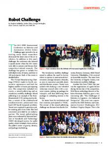
Fig. 1.General diagram of robotic cell.
Fig. 2.Typical 1-unit cycle.
global competition has com mpelled industrial manufacturers to incorporate automatioon and repetitive processing for improving productivity by employing e robotic more cost effective cells. Industrial robots have proven to be m in terms of flexibility, repeatability, and wiith new functions offer improved accuracy. A robotic cell norrmally consists of a feed-in device, an output device, a seriies of processing workstations, each of which repeatedlly performs an identified operation for the part in a fixed ssequence, and one within the cell, as or more robots that transport the parts w shown in Fig.1. The robotic cells can be instructively patterned as a α|β classification [1], where NTENSIVE
α
,
,⋯,
,
,
,⋯,
Here RC stands for the robot cell. Vectorr indicates the cell with n identical workstations at each stagge, and m robots. Note that the feed-in and feed-out devices can be regarded as the special workstations, so that they are deenoted as Ws1 and Wsn respectively. The superscript Gr dennotes the gripper type, say single- or dual-gripper, while the subscript Lo represents the layout of the cell. β lists the constrained conditions in tthe robotic cells, including pick criterion (free/interval pick up), process type (free/non-free process), product type (singgle type or multi types), time metric (travel time matrix, proocess time matrix, Authors are with ABB Corporate Research Centeer, Shanghai 201319, China (e-mail:
[email protected], xinyu.fang@ @cn.abb.com).
978-1-4799-2744-9/13/$31.00 ©2013 IEEE
221
function, each, in general, has a different processing time for a given part. The process time in workstation Wsi is denoted as δTp,i, i. Definitely there is not process time between pair of workstations Wsi and Wsj, 1≤i, j≤n. Therefore, the process time matrix can be expressed as a diagonal matrix: ⋯ ∆ , , , (2)
response surface method, which was then extended to solve cell layout optimization in 6 DOFs by Zhang and Fang [10]. Optimum scheduling is towards optimizing the produce cycle, in which the robot is utilized, as fully as possible, by means of intervening processes, instead of waiting for completing the process. Sriskandarajah, in his series work [1][11]-[14], highlighted on the time-optimal operation scheduling based on polynomial-time approximations for a robotic cell, with single- and dual- gripper. Nevertheless, in most of related studies, constant travel time or additive travel time, and constant processing time, loading/unloading time are usually assumed. This is quite far away from a sophisticated real practical case, which always has different values in these time matrices. Furthermore, due to the dual gripper flexibility, the increase in the combinational possibilities severely complicates its theoretical analysis, so that there were only a few papers contribute to the scheduling in dual-gripper robotic cells. Additionally, the above model is only available to either a single- or a dual gripper robotic free-process cell, where the robot is only employed for material handling. In this paper, a framework for scheduling in a singlegripper robot cell is established firstly. And then an analytical approach providing insight into all feasible 1-unit cycles of a dual-gripper robotic cell is constructed. The combinatorial aspect of the problem with the constraints of interval pick-up and inadmissible path, which is most frequently encountered in real-life robotic cell, is explored. Both of the material handling and non-free process cell are also considered. In implementation scenarios, the results of cell operation intuitively provide indication of the 1-unit robotic cell capacity with single- or dual-gripper. The resulting diagrams provide a clear overview of the scheduling and links between throughput and cell pattern, by comparing the resulting increase in revenue with the additional equipment costs. The remainder of paper is organized as follows. The time matrix and cycle time is derived in Section 2, and the scheduling method for singleand dual-gripper robotic cell in Section 3 and Section 4 respectively, followed by implementation scenarios. Section 6 concludes the paper with some remarks.
Similarly, a sophisticated model has different values for loading and unloading time at each workstation Wsi. They can be denoted as δTl,i and δTu,i respectively: ⋯ ∆ (3) , , , ∆
,
∆
,
0 ,
,
⋯
,
⋯
0
,
(4)
,
,
,
(5)
,
In this kind of cyclic production, cycle time is referred to the duration during which the sequence of the movements and operations is completed in a normal iteration to produce the part. The straightforward approach for computing the cycle time is to sum all of the times cost in a normal iteration of the part production. It can be calculated as:
(6) ,
where,
,
,
⋯ 0 0
,
(7) ⋯ ⋯
(8) 0
They represent the number of the processing times on Wsi and travelling times between Wsi and Wsj. For a 1-unit cycle, each process occurs only once during the part whole producing process, namely ci=1. Actually, more or less constraints exist there in the reallife robotic cell:
In a complete production process for an identified part in a robotic cell with n workstations, come four main sub-tasks: traveling, processing, loading and unloading. The robot travel time between any two workstations Wsi and Wsj, 1≤i, j≤n, can be denoted as δTt,ij. Since the travel time between any two workstations are neither constant nor additive, as supposed in most previous literatures, therefore, the travel time can be expressed in a matrix: ,
⋯
,
A natural and widely used measure of productivity is throughput, the number of finished parts produced per unit time slot. Normally, a robotic cell refers to the production of finished parts by repeating a fixed sequence of robot moves, until the required production is complete. Thus, each element of the cycle time matrix can be expressed as:
II. TIME MATRIX AND CYCLE TIME
0
,
A. Inadmissible path If the travel between a pair of workstations Wsi and Wsj is not available, then δTt,ij=∞ or σij≡0. B. Interval pick-up If the processed part should be unloaded from the workstation Wsi and loaded to the next process Wsi+1 in a required time window, an allowable handling time slot should be introduced. In an n-workstations robotic cell, the allowable handling time slots after each process can be summarized as a vector:
(1)
Since each of the n workstations performs a different 222
,
,
⋯
,
(9)
as shown in Fig. 4, can be calculated d as: (11)
Free-pick-up robotic cell can be regardded as a special example as Ts,i=∞, 1≤i≤n.
where
C. Non-free process If the robot is occupied to implementt the process on workstation Wsi, thus Wsi is called as a “nnon-free” process workstation. A matrix, in terms of “free/nonn-free” process is introduced by the notion “0” and “1” of eachh element. ⋯ (10) , , , III. SCHEDULING IN ROBOT MOVE WITH SINGLE-GRIPPER In robotic cells with a single-gripper robbot, a part cannot be moved from its current workstation to thhe next if the next one is occupied. One popular notation is based on the concept of activity, according to the definitiion given in prior art [1]. Here an enhanced definition of activvity Ai is proposed by considering the operations in engineerring practice. An activity consists of the following sequences of actions: • The robot moves to Wsi-1; • The robot uploads a part from Wsi-1; • The robot travels from Wsi-1 to Wsi; • The robot loads this part onto Wsi; • The robot handles the part on Wsi iff it is a non-free process workstation ; • The robot cell identifies the status for thhis activity; • Waiting for next activity. The standard producing order for a 1-uunit cycle with n workstation in Fig.2, can be translated to sequence S=(A2, A2, ⋯, An), with the scheduling scheme in Fig.3.
(12)
,
max
,
max
,
,
,
,
,
,
(13)
,
,
(14)
(15)
,
and ,
,
,
,
(16)
Thus the optimizing objective in the form of α|β|γ, d as: mentioned above can be summarized : min , (17) To be feasible, an activity scheeduling must meet four criteria: • The robot cannot be instructeed to load an occupied workstation; • The robot cannot be instructed to unload an unoccupied workstation; d to unload an occupied • The robot cannot be instructed workstation, till the process is finished; fi • The robot can only pick a part with w an empty gripper. A complete specification of state of a single-gripper robot n-workstation cell would be unduly burdensome for specifying the robot move cycles of o interest. If only the 1unit cycle is considered, there are a (n-1)! candidates of activity sequences S.
Fig. 3. 1-unit cycle producing order described by activiities.
Fig. 4. Optimal scheduling for a 1 unit cycle.
Since it is to find an optimal scheeduling of robot move to be executed repeatedly in a steady cyclic manner, which activity acts as entrance of thee loop is not minded. Therefore, the loop is supposed to start s from the activity Ai, with the longest processing time. As A a result, the number of identified candidates of activity seq quences is reduced to (n2)!. By the following algorithm, the cycle time of each feasible activity sequence Si, 1≤i≤(n-2)!, can be calculated. Algorithm:
This is named as the standard produce seequence. Between each pair of activities, it is the processingg action on every workstation and the robot should fully wait for the process. Obviously, given there is a long processinng time on a freeprocess workstation Wsx, the robot coould perform an alternative task, rather than fully waiting foor the completion of Wsx. Without loss of generality, it is assum med that after the part loaded on Wsx, the robot performss an intervening activity sequence (Aj, Aj+1, ⋯, Aj+k) to impleement the process from Wsj till Wsj+k-1, and unloads the ppart from Wsj+k-1 followed by moving to Wsj+k and loadingg the part on it, 1≤x