ROBOTIC APPLICATION FOR MULTIPLAYER ONLINE GAME Micael S. Couceiro1, Carlos M. Figueiredo2, J. Miguel Luz3 C. Lebres4, J. Carvalho4, N. M. Fonseca Ferreira4
Institute of Engineering of Coimbra, Dept. of Electrotechnical Engineering Quinta da Nora, 3030-199 Coimbra, Portugal, email:
[email protected];
[email protected];
[email protected] {clebres,carvalho,nunomig}@isec.pt4.
Abstract: This work presents a development of robotics team of hockey. This team is controlled in real time through the Internet. We will approach different kind of problems like the delay of robot response as well as the synchronization of all the information to be sent. This paper describes the physical structure and electronic system of the robots as well as the implemented algorithm. Keywords: Hockey, Robotic, Servo Motors, Internet, Communications.
1. INTRODUCTION In 1970 a group of researchers created the first interactive online game [1]. Nowadays, online games are the main focus of all games developers. This kind of games provides multi-user gaming that encouraged players to compete against one another. This project consists in the evolution of online gaming allowing the control of a hockey robot in real time through the internet. The idea of robot playing soccer/football game was first mentioned in a paper entitled ‘On Seeing Robots’, in 1992. Since 1997 it’s possible to compete against other teams in contests like RoboCup [2]. The only catch is the need to build or simulate a team of autonomous robots controlled with PID or Fuzzy Logic [3]. We want to give to the user the chance of controlling a robot like playing an online game competing against other users. The paper is organized as follow. Section two provides an overview of the physical structure and the section three refers to the application software analysing the delay of the robot response due to communications and the implemented solution in order to minimize the impact of the delay. Finally, section four is the main conclusion.
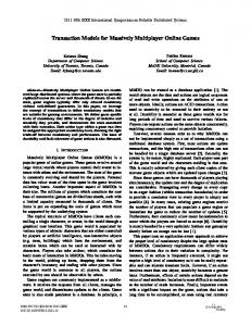
Fig. I – OKISEC Team 2. PHYSICAL STRUCTURE Each robot player has approximately 25 centimetres tall, measured from the bottom of the drive wheels to the top of the head without the antenna and 30 centimetres with it. The widest points are from wheel to wheel measuring approximately 20centimetres. Figure II shows a robot player made in AutoCAD. All the 3D physical structure is made in real scale. The overall weight of the structure is a primary concern to ensure a long battery life. The power source for all electronics and actuators are carried onboard and no external power may be used. The entire robot weighs approximately 1.12 kilograms.
Fig. II – Robot player made in AutoCAD The robot has two wheels, each one connected with the help of two gears and a racing belt to a separate servo motor acting as an electric DC motor as can be seen in Figure III. The steering is accomplished by adjusting the power and direction of the motors separately. The speed and direction of each wheel are controlled individually. This setup gives an easy control of the robots movements and, at the same time, is efficient and easy to implement. The robot has a high turning radius and the top speed is only dependent on the maximum output of the motors.
Fig. III – Drive System Bottom view. Contrarily to other hockey robots built with a static stick [4], each robot has a controlled stick to drive the ball at the front of the robot. The control is made by a servo motor so the player can easily shoot. The ball can be reached by the stick in a maximum front range of 10centimetres. The hockey field is made of a resistant canvas that can be moulded thanks to this texture. Field dimensions are 2.40x1.38 meters with moulded lateral limits of 3centimeters. The four black crosses shown in Figure IV correspond to the initial position of the four robots. They need to be placed on those positions when game starts and after every goal. Each robot will have three servo motors. One will be in charge of controlling the stick; the others two will be hacked without removing the potentiometer so they can be used as common DC motors [5].
Fig. IV – Hockey Field The speed and direction of those motors will be controlled by a PWM wave. Regulating the internal potentiometer to a duty cycle corresponding to 90º, it will be possible to change direction and speed increasing or decreasing the duty cycle having as reference the one corresponding to 90º. The power consumption of those motors may differ depending on the movement that is made, the strength made by the stick, etc. Even so, in the worst case, the motors all together would originate a current consumption of approximately 600mA. An important aspect on the OK robots is the perspective of evolution. With this in mind, it was developed a structure that can be upgraded both at software and hardware levels. This was made thinking ahead for new developments and future research and education. In the electronic board’s elaboration it was decided to sub-divide the main board in four boards, each one entrust with a specific task: power supply, control, motors’ connection and communication. A clear advantage is to be able to detect malfunctions easily. Another advantage is to plug sensors or other actuators without making any changes (depending on sensors and actuators characteristics) because all the IN/OUT pins of the PIC® microcontroller are enabled. The software used for the Printed Circuit Board, ORCAD includes subprograms for schematics drawing (Capture CIS) and PCB design (Layout Plus). Both are very powerful tools. They are both user-friendly and have a wide range of component library. In case you can't find a suitable PCB footprint or schematics symbol for your component, you can create new symbols and footprints. Also you can arrange your footprints in newly created footprint libraries. In this project, we needed to create a few footprints of our own. The power source circuit (Figure V) is divided in two distinct sources (with different voltages). Using the same battery and with two voltage regulators LM7805 we supply 5V to the whole system except the motors that will have a voltage close to 6V exclusively for them. The well known LM7805 from Fairchild or ST Microelectronics contains all the circuitry needed to accept any input voltage from 7 to 18 volts and produce a steady 5V output, accurate to within 5%
(0.25V). It also contains current-limiting circuitry and thermal overload protection, so that the IC won't be damaged in case of excessive load current; it will reduce its output voltage instead. The U1 regulator is able to produce an output voltage close to 6V thanks to the resistors R2 and R3. The U2 regulator produces a steady 5V output. The C1 and C3 capacitors serve to help keep the power supply output voltage constant when load conditions change. The electrolytic capacitors smooth out any long-term or low frequency variations. The OK Robot can be switched on/off with SW2. The LED D1 serves as a pilot light to indicate when the power supply is on. JP3 will deliver the input voltage to the other boards having as reference the ground delivered by JP1 (battery terminals). A system for detecting low batteries was implemented on this board. The player will be alerted with a yellow LED when the battery is close to 7V. This is made by a voltage comparator. A comparator circuit compares two voltage signals and determines which one is greater. The result of this comparison is indicated by the output voltage: if the op-amp's output is saturated in the positive direction, the non-inverting input is a greater, or more positive, voltage than the inverting input, all voltages measured with respect to ground. If the op-amp's voltage is near the negative supply voltage (in this case, the ground potential), it means the inverting input has a greater voltage applied to it than the non-inverting input. The LM311N voltage comparator from National Semiconductor can be used for these applications having a number of unique features. The voltage reference is made with a zener 3V9 comparing it with the inverting input voltage related with the battery voltage. The battery voltage to switch op-amp’s output can be chosen changing the relation between two resistors (voltage divider). Depending on the TTL level received the PIC will switch the LED ON or OFF indicating the state of the battery. The robot “brain” is placed in the control circuit. The microcontroller PIC18F2580 will receive and process all the information sent from the user and will execute the respective actions. All ports of the microcontroller are available to future upgrades. Information about motors’ movement is received on motor connection board. This board was designed to plug servomotors directly being able to support up to eight motors. That’s the only board that receives the voltage close to 6V. It also receives I/O port B from the PIC where each pin controls one servo motor. The communication circuit receives information from server through [433; 434] MHz radio frequency or RS-232 (serial) with the commutation of a switch. The received information from radio frequency doesn’t need any kind of conversion. The module can be directly connected to the PIC.
Figure V – Server Communication circuit The received information from RS232 reaches the MAX232 from Maxim converting RS232 signals in TTL to the microcontroller. The circuit of the server communication is a single board (Figure V), which is directly connected to the server and establishes communication with robots. A LM7805 voltage regulator regulates the voltage to 5V, enough to supply the entire circuit. That means that a common battery of 9V will be enough (common 9V pile). The connection to the server is made by RS-232 through MAX232. To feed the whole system we need a battery with high durability, little, light and with small costs. Attending to those conditions we will use batteries based on common rechargeable piles. The battery used was from Graupner with 9.6V and 1500mA. Those batteries require periodical attention. They have a specific charging time (between 6 to 8 hours) with a specific voltage and current of 12V/200mA. The batteries state has influence over robot’s movement and that’s why users will be alerted by a yellow LED on robots head when batteries are low. The batteries have a large durability and they can stand up for more than one hour and a half when playing. In order to implement an algorithm to control speed and position of the servomotors, simple mathematic analysis is required. The purpose of a standard servo is to bring the shaft into a certain position and to keep it there. A train of digital pulses is expected at servos input. The duration of these pulses determines the position that the shaft must assume. Respecting to our servomotor HS-311 from HITEC, the shaft will reach position zero when sending a digital pulse of 1ms in a periodic cycle of 20ms. If the servo receives a digital pulse of 2ms the shaft will reach 180 º positions. All other positions can be calculated considering those two positions. As long as the coded signal exists at the input line, the servo will maintain the angle position of the shaft. The easiest way to achieve this with PIC is to use timer interruptions: one for each servo. To simplify, two timer interruptions will be used, one will be dedicated to both servos of the wheels and the other to the servo of the stick. With PIC18F2580 it’s possible to use two timer interruptions of 16 bits with the same configurable structure (timer 1 and timer 3). Each interruption will be called when the timer reaches the overflow (65535 to 0). To determine how many increments are needed
to reach the overflow, we have to consider the clock oscillator and configurable prescale (1) and (2).
V
⇔ 4 × prescale × 1000 20000000 ⇔n = Tms × = 625.Tms count 4 × 8 × 1000
(1)
counter = 65535 − n
(3)
n
count
= Tms ×
Fcrystal
count
= 65535 − 625.Tms
0.16 × 360 = 0.96 s 60
(5)
These would be without load. In order to simplify we will consider the time of a complete rotation equal to one second.
T ≈ 1s rotation
(6)
The perimeter of the wheel can be calculated in cm as we can see in equation (3).
P = 2π × 3 = 6π cm wheel
(7)
One complete rotation takes one second so the perimeter will be the distance travelled per second.
V
wheel
= 6π cm / s ≈ 19 cm / s
≈ 38 cm / s
(9)
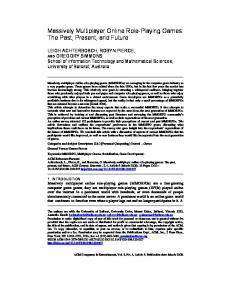
3. APPLICATION SOFTWARE In order to develop this project it has been necessary to combine different tools related mainly to three differentiated tasks: the communication between the clients and the server, the communication between the server and the robots, and the video transmission. A system controlled over web in real time can’t be done. Real time does not exist in web communications. What does exist is something near to real time [6]. Communication is based on TCP Sockets between every client and a server that will add data and send it to robots with a Radio Frequency interface. Figure VI shows the communications system.
(4)
Servos, originating from their application in model building, are usually used to operate arms, feet and other ‘tools’ of a robot. In addition to these obvious uses they are also very suitable as a motor to drive the wheels of a robot, for instance. To do this, the standard servo does need to be modified first. The servomotors HS-311 have an operating speed (without load) of 0.19sec/60º to 4.8V and 0.15sec/60º to 6V. Operating at 5.8V we would have approximately 0.16sec/60º. To make a complete rotation it would take: Trotation =
wheel
(2)
The timer will be configured with the time corresponding to the time at off (0 level). Considering that 180º corresponds to a pulse of 2ms and being the top angle, the time at off would be 18ms. For angles lower than 180º a delay will be implemented in the timer interruption in order to reach the correct value for the considered angle. This is due to the lack of resolution (1º corresponds to 5 μs) that unable to impose the angle directly in the timer. The timer will always be initialized with the same value: counter = 65535 − 625 × 18 = 54285
With the gears, the new speed value would be:
(8)
Considering that this would be the speed without load, with the whole structure the speed would be very low for a hockey game. To increase speed, a system of gears was connected to the servomotors doubling the robot’s speed.
TCP
Client Individual Client Data HTTP
Server Video Frame All Clients
Robot 1
Robot 2
…
Robot N
Fig. VI – Data communication between clients and robots Each client will send periodically two bytes containing the information about the direction of the robot and state of the stick. The server will regroup all information received adding the corresponding robot number in the header of each individual client data and finalizing the data frame with the number five (Figure VII). The data is refreshed every 250 milliseconds. This time has been studied to satisfy both Ethernet and internet players so they can play against each other in the same conditions. If server doesn’t receive information about a robot it may mean that no one is controlling it. In that case the server will send data corresponding to resting position. So even if clients don’t send the information at the same time to the server, the information will be synchronized at the server and then broadcasted at the same time to every robot. The communication between the server and robots is made through radio frequency connected to the serial port of the PC.
1…5
100…108 160…161
Number of Robot 5 Æ Ending Flag
Movement of Robot Stick 100 Æ Resting 160 Æ Resting
Fig.VII – Data specification The objective of the video transmission is that this transmission is affected by a minimum latency. Considering that we need a real time control of the robots the video can’t be transmitted by flow (in streaming). There are two types of video transmission. The first one is made for the internal LAN that consists on getting frame by frame with HTTP commands. This one is implemented in a thread giving independency between video and data communications. It requires an HTTP server that can be made with Apache®. Apache® constitutes a well-known and free HTTP server, with available versions for different platforms. The other one is adjusted for Web communications and is based on an ActiveX controller for video transmission. The disadvantage of this last one is that it requires additional software to accomplish the video acquisition to ActiveX controller. The additional software used was Active® Webcam that consists on video transmission over internet for ActiveX controllers, Applets and others.
We can divide this project in two different kinds of software implementation. The user interface made in Delphi® and robot’s code implemented on PIC® and programmed in C® language. Communications are the hardest thing to implement because it needs to be robust and fast. While clients send data to the server, the server will regroup it, adapt it, and resend it to all robots. This kind of coordination needs to be well implemented so that players won’t feel like they’re not controlling their robots as they want to. Client’s software has three main steps: a timer to read keyboard or gamepad information, a timer to refresh the frame acquired by the server and a timer to send information over TCP about robot’s movement. All those timers are based on timer interruptions with no influence on each other. The keyboard or gamepad information will be refreshed each 50ms corresponding to Timer3. The timer to refresh the frame acquisition was implemented in a thread named VideoThread. This is due to the time needed to load the picture that would have its influence on other timers. The simplest way is running the thread with a sleeping time implemented to avoid the thread to run at processors clock speed. The time considered was 150ms giving approximately 6 frames per second.
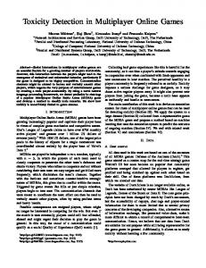
Fig.VIII – Screenshot of OKISEC’s webpage The Web software can also be used in internal LAN but the need of having ActiveX plug-ins installed in the server is reason enough to have software implemented just for LAN players and another for Web players. The frame rate will depend on player’s connection but can reach up to six frames per second. The webpage was made in HTML (Hypertext Markup Language), JavaScript and CSS (Cascade Style Sheets). The HTML is the base language used on internet pages permitting the connection between the different components of the page – image, text, graphics, etc. The JavaScript is used on calendar creation, since it’s not static. The calendar is created in the moment that the page was loaded based on the system data. The CSS were used to format the page and it allows an easier way to reconfigure the website and faster load of webpages. The different contents on the site are loaded on the initial page named index.html with the use of an iFrame. If the server is running for internet players, with Active® Webcam, the video transmission will be available in the page to any user who may wish to see it.
Fig.IX– Interface of Client’s Software The information is sent to the server in a periodic time (Timer1) of 250ms. This means that the robot will make the action between 250ms and 500ms after it is sent (adding the time to send the information to the robot). The server’s software is able to receive information from a different group of clients. Even if just four can play at the same time, the server is open to every client who wishes to know the state of robots (already playing or available).
Fig.X – Interface of Server’s Software The server will also send captured frames to each client who connects to it. We can divide server’s software in three main steps: an interruption to receive each client’s data through TCP, an algorithm to adapt data from all clients and a timer to send information over radio frequency to all robots. To receive the data through TCP the server will have an interruption (TCPserverexecute) that will be called each time it receives any information. That information will be regrouped in a periodic time of 250ms (TimerSerie) depending on the corresponding IP associated to a specific robot (section 3) and will be sent over radio frequency. The captured frame will also be implemented in a timer (Timer2) with a refresh cycle of 150ms. The PIC® microcontroller executes actions while having the chance of receiving new information at any time. We can divide the robot’s software in two main steps: an interruption to get new data received from radio frequency and timers to keep servo motors on the desired position. The interruption to receive new data fires when the received data is available. The robot will ignore any information that doesn’t have it’s predefined number as header. For instance, when robot 3 receives the data from the server it will only save the next two bytes coming after the byte with the value 3 is sent Timers specification is made in section 2. 4. CONCLUSIONS The interface implemented allows the interaction of a remote user with the robots. Besides the obvious didactic interest that designing application like this represents, it is not difficult to imagine that the control via web of a robot may be interesting enough. For example, a similar scheme could be used as a monitoring system for remote vigilance or exploration. The disadvantage of the implemented communication algorithm is the delay introduced in order to have a “fair” game to everyone. Even so, a latency of approximately half a second can insure a more than
playable online game considering that the system communications are divided in two: internet communication and radio frequency communication. In order to decrease the delay the communication system between server and robots should be changed to a Bluetooth® or Wireless® 802.11 interface. Bluetooth’s Piconets can support up to 1 master and 7 simultaneous slave with low power consumption and a range communication of 10 meters. Bluetooth devices are cheap and can transmit data over 1Mbit/s attending to our system. Wireless has the unique advantage of being faster than Bluetooth. Even attending to the boards’ versatility that encloses a wide range of different applications, they could be improved. One of the improvements would be using choppers instead of regulators. That would consist on changing the power source board. This kind of optimization will dramatically improve batteries durability. The most significant advantage of sub-dividing the main board is to be able to replace the power source board with a better one by optimizing the consumption with choppers that can be easily implemented. The stick should be changed to be faster, stronger and controlled. With a servo motor and string system it would be possible to have a controlled strength depending on servo rotation. Another choice would be using another kind of servo like, for example, digital servos that are stronger and faster than standard servos. REFERENCES [1] http://webhost.bridgew.edu/jnewcomb/history_.h tm [2] http://www.sonycsl.co.jp/person/kitano/RoboCup /RoboCup-old.html [3] Pedro Luís Cerqueira Gomes da Costa (1998). Controlo de uma Equipa de Robots Móveis [4] Kristofer Hallen, Johannes Hjorth and Magnus Jacobsson (2003). Project report Robotics and Autonomous systems [5] Seattle Robotics Society (2000). Hacking a Servo [6] R. Siegwart (1999). Mobile Robots on the Web: Interactive Exploration of Distant Places