Robotic automation in computer controlled polishing
Recommend Documents
Feb 6, 2016 - integrated in hardware and software. Three key ... together, describing our vision of the automated manufacturing cell, where the operator interacts at cell rather than machine level. This ..... Horiz. force directed away from the robot
William Arnold c. , Brian Ramsey b a. NASA Postdoctoral Program Fellow, MSFC, Huntsville, AL 35805 b. Space Science Office, NASA/MSFC Huntsville, ...
The process parameters are the speeds of the lap and the mandrel, the tool's influence .... Figure 8 compares the PSD distribution of the polished surface when the tool .... See http://ixo.gsfc.nasa.gov/science/performanceRequirements.html. [2].
This paper presents the solutions adopted for a robotic polishing cell for mold manufacturing. Mold finishing is frequently carried out manually; these kinds of ...
Abstract- Polishing is a highly skilled manufacturing process with a lot of constraint and interaction with environment. Unfortunately, manual polishing process ...
âRobotsâ are software tools that have emerged to simplify business process delivery. The technology ... How we can h
healthcare and financial services can also utilise RPA. It can be integrated into ... Banks can embed RPA in credit card fraud management, including account ...
ways to drive cost improvements and operational ... Robotic Process Automation (RPA) explained ... Banks can embed RPA in credit card fraud management,.
are treated, so that the use of a constant contact force control has also been considered. ... tems with contact pressure control using CAD/CAM data.
Mar 22, 2002 - scale, operations such as trenching and footing formation re- quire precisely ... trial robot fitted with a bucket as the end-effector. Although.
There are many opportunities for RPA robots to work alongside human workers as assistants, and knowing this fact will he
Robotic Process Automation (RPA) is the latest evolution in business ... software can imitate human actions and work acr
Sep 16, 2012 - successful, this may justify future development of BCI-controlled lower extremity prostheses for free overground walking for those with complete ...
The first step in producing glazed porcelain dishes is molding of raw material granules. Then, the biscuit of the dishes is formed. This process is performed by ...
Innovations Deserving Exploratory Analysis (IDEA) Programs. Managed by the .... APPENDIX Economic Analysis of Controlled
Mar 16, 2002 - Invention Award, CTS Young Inventor's Award, and was selected as one of the Ten Outstanding Young. Men of
oxygen for high speed fire polishing or propane-oxygen for convenient and .... However, our goal is to repair the glass
Abstractâ This paper summarized a robotic car control by ... Records state that it is the first .... [1] R. Sharma, K. Kumar, and S. Viq, âDTMF Based Remote.
arm. The robot is controlled using Arduino Uno as the brain of the robot, connected to the internet via Arduino Ethernet ... operator access the robotic arm via the internet to control it. .... âManual Settingâ for manual control of the robotic a
project that is servo motor analysis and accuracy test. ... directly powered by servo motors. Acrylic ... One company gives a free-to-use relay infrastructure that is.
The robot is the NOMAD-200 that has a server workstation that runs on. UNIX ... The controller is embedded with a webserver written in HTML, when a computer ...
MultiMAX. The MultiMAX uses Controlled. Automation's shape cutting technology
to produce top quality thermally cut parts. With a core machine design of.
KeywordsâAndroid, Bluetooth, Home Automation, User-friendly, 8051 Microcontroller. 1. INTRODUCTION ... Eclipse IDE with Android development (ADT).
Robotic automation in computer controlled polishing
Feb 6, 2016 - Robotic automation in computer controlled polishing. D. D. Walker ddwlkr@aol.com. University College London, Dpt Physics and Astronomy, ...
J. Eur. Opt. Soc.-Rapid 11, 16005 (2016)
www.jeos.org
Robotic automation in computer controlled polishing D. D. Walker [email protected]
University College London, Dpt Physics and Astronomy, London, WC1E 6BT, UK ˆ University, St Asaph, LL17 0JD, UK National Facility for Ultra Precision Surfaces, OpTIC, Glyndwr University of Huddersfield, Centre for Precision Technologies, Queensgate, Huddersfield, HD1 3DH, UK Zeeko Ltd, Coalville, LE67 3FW, UK
G. Yu
ˆ University, St Asaph, LL17 0JD, UK National Facility for Ultra Precision Surfaces, OpTIC, Glyndwr
M. Bibby
Zeeko Ltd, Coalville, LE67 3FW, UK
C. Dunn
University College London, Dpt Physics and Astronomy, London, WC1E 6BT, UK
H. Li
ˆ University, St Asaph, LL17 0JD, UK National Facility for Ultra Precision Surfaces, OpTIC, Glyndwr
H. Y. Wu
University College London, Dpt Physics and Astronomy, London, WC1E 6BT, UK
X. Zheng
ˆ University, St Asaph, LL17 0JD, UK National Facility for Ultra Precision Surfaces, OpTIC, Glyndwr
P. Zhang
ˆ University, St Asaph, LL17 0JD, UK National Facility for Ultra Precision Surfaces, OpTIC, Glyndwr
We first present a Case Study – the manufacture of 1.4 m prototype mirror-segments for the European Extremely Large Telescope, undertaken ˆ University. Scale-up to serial-manufacture by the National Facility for Ultra Precision Surfaces, at the OpTIC facility operated by Glyndwr demands delivery of a 1.4 m off-axis aspheric hexagonal segment with surface precision < 10 nm RMS every ˜four days, compared with a typical year or more for an one-off part. This requires a radically-new approach to large optics fabrication, which will inevitably propagate into wider industrial optics. We report on how these ambitious requirements have stimulated an investigation into the synergy between robots and computer numerically controlled (‘CNC’) polishing machines for optical fabrication. The objective was not to assess which is superior. Rather, it was to understand for the first time their complementary properties, leading us to operate them together as a unit, integrated in hardware and software. Three key areas are reported. First is the novel use of robots to automate currently-manual operations on CNC polishing machines, to improve work-throughput, mitigate risk of damage to parts, and reduce dependence on highly-skilled staff. Second is the use of robots to pre-process surfaces prior to CNC polishing, to reduce total process time. The third draws the threads together, describing our vision of the automated manufacturing cell, where the operator interacts at cell rather than machine level. This promises to deliver a step-change in end-to-end manufacturing times and costs, compared with either platform used on its own or, indeed, the state-of-the-art used elsewhere. [DOI: http://dx.doi.org/10.2971/jeos.2016.16005] Keywords: Robot, polish, smooth, automation, CNC, computer controlled, precessions
1 INTRODUCTION The European Extremely Large Telescope (‘E-ELT’) [1] is a 39.3 m aperture segmented mirror telescope for the optical and near-IR wavebands, under construction by the European Southern Observatory (ESO). One challenge is that 931 mirror segments are required for this project, with tight surface tolerances [2]. In comparison, each of the two Keck 10 m telescopes [3] has 36 segments, yet the construction times are not dissimilar. A new approach to manufacturing 1–2 m class optics is now needed; repeated prototyping is no longer appropriate. We have previously reported [4] on successful completion, at
the National Facility for Ultra Precision Surfaces, of a 1.4 m Master Spherical Segment (R = 84 m), which is used as a comparator to assert segment-matching and absolute radius-ofcurvature. We have also described completion of three 1.4 m across-corners, hexagonal, off-axis aspheric mirror segments, with formal acceptance [5]. CNC grinding was performed using the BOX™machine [6] at Cranfield University. Much of the underlying process development was conducted on UCL’s Zeeko IRP1200 CNC polishing machine, and pre- and ˆ University’s corrective polishing of segments used Glyndwr IRP1600, both located at the National Facility. Uniquely, the segments were hexagonal throughout, with all metrology to
Received October 06, 2015; revised ms. received November 20, 2015; published February 06, 2016
ISSN 1990-2573
J. Eur. Opt. Soc.-Rapid 11, 16005 (2016)
D. D. Walker, et al.
• Geometric distortion and magnification of optical test data (e.g. interferograms) • Inadequate data-sampling (projected pixel sizes) at edges and perforations 5. Contamination of the part, machine, or slurry-system from splashes during wash down 6. Collisions with the part when installing or removing tooling or on-machine metrology instrumentation (from the machine tool-chuck or other interface) 7. Damage to edges or corners of parts when fitting or removing protective covers 8. Human errors processing metrology-data, generating tool-paths, transfers of wrong or corrupted files etc., leading to local surface-removal at laterally-displaced locations, or with the incorrect depths
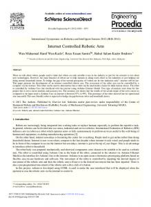
FIG. 1 Segment polishing on Zeeko IRP1600 machine at the National Facility.
support polishing conducted on-machine. Meanwhile, ESO has opted for a process-route polishing circular blanks, cutting hexagonal, followed by ion-beam figuring. Therefore, a fourth, circular segment has passed acceptance, completed to a more stringent mid-spatial specification demanded by ESO [7]. This paper uses segment mass-production as a Case-Study, but particularly highlights the impact of the methodology we are advancing on smaller optics and other precision surfaces.
The risks above are exacerbated when the part is removed from the machine to a metrology station between iterative process-runs. Furthermore, the manual interventions demand significant time. With automation, risk and time could be significantly reduced. The ultimate objective is to close the iterative process-loop automatically, creating the Integrated Manufacturing Cell. This is a step beyond the state-of-the-art, in that we consider both: • bespoke parts and small production runs, each of which will be diverse in specification • iterative processes, where each step depends on the measured output of its predecessor
2 THE NEED FOR AUTOMATION We first present in Table 1 the principle operations required for segment manufacture, other than actual polishing. The last two columns review potential for automation for manufacturing meter-scale parts e.g. mirror-segments, and also the potential for smaller parts such as instrumentation optics etc. ‘N’ indicates that robot automation is not practical on grounds of the mass to be handled; ‘Y’ that it is practical, and ‘?’ that it may be possible under some circumstances. These last two columns are referred to in Section 3. From Table 1, we identify the following potential sources of risk of damage to the part during manufacture, relevant to large parts, and at varying degrees to many small parts as well: 1. Accidental damage when mounting the part on its fixture (e.g. waxed to a carrier for small sizes; interfaced to a mechanical or hydrostatic whiffle tree for large parts) 2. Accidental collisions when handling the fixtured-part off-machine, or when mounting on-machine 3. A gross polar-rotation of the part which preserves the visual appearance (e.g. any rotation of a circular part, 60◦ rotation of a hexagon, 90◦ for a square part etc.) 4. Alignment inaccuracies of the part on the machine in any of six degrees of freedom, leading to mapping errors between coordinate frames of part, machine-CNC, and metrology data. These inconsistencies can comprise of • X, Y offsets; polar rotation, tip/tilt
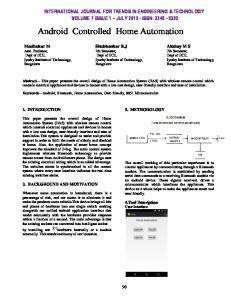
3 IMPLEMENTATION OF AUTOMATION Robots typically provide six degrees-of-freedom to an ‘end effector’, which is the specialized functional device. They are most frequently used for repetitive operations, and their software is configured primarily for this type of operation. Note that, in the context of Table 1 above, some tasks, such as loading heavy parts, are beyond the realistic capability of robots. In these cases, automation would require a bespoke handling device. Robots have been widely deployed for automation in several industries. A typical example is automobiles massproduction, where installations may contain many thousands of industrial robot arms performing repetitive tasks such as welding etc. An example which is more relevant to surfacequality, concerns the eye’s keen sensitivity to local surface ripples on body-panels (which are free-form surfaces). This is very difficult to achieve manually, but has been achieved with ‘trajectory-control’ of a robot [8], which goes beyond the more usual ‘pick and place’. The use of a robot arm and end-effector tooling such as grippers, allows the development of a manufacturing cell, in which multiple CNC systems such as grinders, polishing machines and metrology, may be tended by a robot. The current prototype system, combining an IRP600 machine and a metrology station (shown in Figure 2(a)) has been developed to the stage where it can execute the following cycle automatically with no manual access or intervention required:
16005- 2
J. Eur. Opt. Soc.-Rapid 11, 16005 (2016)
Task Mounting part on machine Aligning part on machine Washing down the part On-machine texture interferometer On-machine sub-aperture stitching interferometer On-machine profilometer Aligning full-aperture test (Optical Test Tower) Processing metrology data Computing tool paths Initiate polishing run
D. D. Walker, et al.
Current method of operation for segment manufacture Manually-operated bespoke handling trolley Operator-input commands to software Manual – hose and pads etc Deployment is manual. Machine-motions and data-capture for multiple samples is automated. Manual deployment. Machine motions and data capture for multiple samples – automated Deployment manual – by fork-lift truck Profilometer scan-execution – automated Operator-input software-commands to tower control system and micro-positioners Operator-input software commands Operator-input Tool Path Generator commands Operator-input software commands
Automation by robot/software? Large parts Small parts N Y N N Y Y Y Y Y
Y
?
N
Y
Y
Y Y Y
Y Y Y
TABLE 1 Summary of current manual interventions which create risk.
1. unloading a fixtured part from a Schunk pneumatic chuck on a metrology station 2. mounting using the similar chuck installed on the Zeeko machine 3. conducting on-machine probing using the bonnet and load-sensing within the tool spindle, to establish the coordinate frame of the part’s surface in that of the machine 4. initiating and executing a polishing run 5. demounting the part and re-loading on the metrology station Indicative tests have been conducted, using CNC on-machine probing, to determine the angular orientation of the part in the CNC machine coordinate-frame after robot-loading, then the orientations after robot unloading/re-loading cycles. The angular error (mean-error + 2σ) was 0.033◦ in Machine X and 0.010◦ in Y.
(a)
This system mitigates many risk items above, and is wellsuited to operation in a controlled manufacturing environment, in which human ingress for direct interaction with machines is undesirable. Going beyond this, metrology setuptime can have a major impact on total process-time, and previous work has demonstrated successful automation of fullaperture interferometry, sub-aperture stitching interferometry, and texture white light interferometry [9, 10]. The incorporation of such metrology systems into the existing prototype robot cell is expected to be ideal for developing fullyautomated closed-loop manufacturing.
4 COMPARISON OF CNC POLISHING MACHINES AND ROBOTS FOR PROCESSING SURFACES PrecessionsTM
(b)
FIG. 2 Fanuc robots for automation and polishing. a) M-20iA between metrology station
The process is based on inflated spherical compliant tools (‘bonnets’) of different radii – comprising either a thin membrane, air-pressurized in the range 0.01–0.3 MPa, or a solid elastomer. Bonnets naturally adapt to varying local aspheric or free-form topography. The active polishing or other
(front) and IRP600 (rear) b) R-2000iB in polishing pose.
pad is typically pre-molded to the matching radius of curvature and cemented to the bonnet. This tool is then advanced
16005- 3
J. Eur. Opt. Soc.-Rapid 11, 16005 (2016)
D. D. Walker, et al.
Bonnet radius R
Spot diameter S
(mm) 20 20 40 40 80 80 160 160
(mm) 5 7.5 8 15 12 30 17 60
∆Z sensitivity for a 5 mm spot from a R20 bonnet then sits just below the machine positioning specification, but such small bonnets are not normally used on this large machine.
Change in Z offset resulting in 10% change in spot area (µm) 17 39 22 78 25 156 25 313
TABLE 2 Z-offset ∆Z sensitivity for different bonnet radii and spot sizes.
towards the surface of the part, and touch-on established by a load cell in the polishing head. The 3D surface of the part is then probed using the bonnet, to create a 3D surface-map in the machine coordinate frame. The bonnet is then advanced further towards the surface through a pre-determined ∆Z (‘Z-offset’), to create the required circular contact area (‘polishing spot’). Any discrepancy in ∆Z translates into a variation of volumetric removal rate. In the cases of treating edges, ∆Z is decreased as the edge-zone is encountered, so that the polishing spot does not roll-down the edge [11]. The full spot-size produced by a spherical bonnet compressed against a flat is given by ( D/2)2 = ∆Z (2R − ∆Z ), which reduces to ∆Z ∼ D2 /8R when ∆Z R, where D is the spot diameter, R is the bonnet radius-of-curvature, and ∆Z is the bonnet compression.
Turning to the case of an equivalent large robot, such as the Fanuc R-2000iB, the mechanical configuration comprises a set of six rotational axes, each being cantilevered off its predecessor. The positioning repeatability is quoted as +/- 0.2 mm. Absolute positioning is not specified. The design is not only considerably less stiff than a Cartesian machine, but the interdependent flexing of different components as they move renders absolute calibration of positioning errors challenging. Nevertheless, progress has been reported in the literature on full-pose calibration of robots, for example, Driels et al. [12] describing work in the early 1990’s, and Ji et al. [13] in 2007. A typical method reported is to develop a kinematic model of the robot, and sample parameter-space using a coordinate measuring machine (CMM) to measure errors in the endeffector pose. The principal conclusion from the literature is that such methods can calibrate robots successfully, with accuracy ‘approaching that of repeatability’. However, this presupposes that a CMM of equivalent working volume is available. Therefore, laser trackers are largely superseding Cartesian CMMs, as reported by Alzarok et al. [14]. Their work concluded that repeatability was ‘sensitive to moves requiring large rotary movements’ (‘typically near singularities in the kinematic loop’), which they attributed to thermal effects in the drives. Note that the reported repeatability data were for the robot stationery after each repeated move. In the case of deploying polishing-like tools on robots, there are further complicating factors: 1. the wide range of tooling payloads that may be mounted on the end-effector
This is modified for curved surfaces, where convex gives smaller spots and concave larger. Volumetric removal rate then depends on the polishing spot’s area (other things being equal). Calculated numbers for the change in Z offset (µm) which would cause a 10% change in spot-area on a flat surface, are given in Table 2. A distinguishing feature of the CNC polishing machines is that the two rotary axes (A, B) that incline the polishing spindle to follow or offset from the local surface-normal constitute a virtual pivot: A and B intersect at the bonnet’s centreof-curvature. A and B errors then do not propagate into errors in ∆Z, or into lateral position of the polishing spot on the surface, unless there are errors in the bonnet’s surface-form with respect to a sphere centred on the virtual pivot. In practice, this is circumvented by skimming the bonnet and pad on the machine, using a fixed hard tool and moving the A and B axes. As regards correcting in software for repeatable machine errors (e.g. straightness and orthogonality of axes, lead-screw errors etc.) the machine behaves as a simple, stiff, XYZ Cartesian machine, and is amenable to standard calibration procedures. The functional specification of the IRP1600 machine, as used for polishing prototype E-ELT segments, quotes XYZ slide positioning errors of < 20 µm over full travel. Standard bonnets are available with R = 20, 40, 80 and 160 mm. As per Table 2,
2. lateral forces on the end-effector due to drag on the tool from friction with part 3. the dynamic nature of surface-processing, conducted when the robot is in constant motion with variable accelerations, dispersed amongst the different joints These constitute dynamically changing load-cases which will disturb, not only the parameters of a kinematic calibration model, but the underlying level of the repeatability itself (due both to mechanical and thermal effects). With this in view, we have conducted tests to quantify the second point above. We configured three robots in a typical (but static) polishing pose, as illustrated in Figure 2(b). End-effectors (tool spindles) were removed, and forces applied near the end-effector interface using elastic cable and a digital ‘spring balance’. Comparative tests were performed on the IRP1600 machine. In this case, the tool-spindle is integral with the machine, and forces were applied at the spindle-housing and displacements on the structure adjacent to the tool-interface. Using a linear displacement sensor, we measured displacements near to the application points for the forces, and hysteresis on removing the forces. Coordinate conventions for this paper are given in Table 3, and results in Table 4. Each result is an average of three sets of three measurements (no-force ⇒ force ⇒ no-force), with the end of the robot manually vibrated before each set. The first resonant frequencies have also been measured with a spec-
16005- 4
J. Eur. Opt. Soc.-Rapid 11, 16005 (2016)
Coordinate X Y Z
D. D. Walker, et al.
Convention for robots Horiz. lateral force Horiz. force directed away from the robot plinth Force pulling vertically upwards
Convention for IRP1600 Horiz. force parallel to bridge Horiz. force away from the bridge Force pulling vertically upwards
TABLE 4 Measured lateral displacement and hysteresis, and first resonant frequencies, on four platforms.
trum frequency analyser (100Hz sampling rate). In the case of the R-2000iB 125L, the spindle was attached, in order to give a realistic comparison with the Zeeko IRP1600. Note that we define the ‘reach’ of the IRP1600 machine as the diagonal of the XY envelope of tool-traverse (Z is a separate axis). Robot reach is as per specification, corresponds to the arm being extended horizontally, and is measured from the base rotational axis. The Fanuc R-2000iB 125L is therefore roughly equivalent to the IRP1600 in its size capability for polishing components, allowing for the robot-pedestal being mounted alongside the part. From the above discussion, we have demonstrated for the first time how the CNC polishing machine and robot platforms are complementary. The former can deliver high stiffness and first resonant frequency, and an absolute positional accuracy an order-of-magnitude better than the static positional repeatability of the equivalent robot. However, the robot wins by a similar margin in speed and acceleration. Optimum roles are as follows: The CNC polishing machine is therefore well-matched to: • bonnet-type processes for aspheres and freeform surfaces, where high tool rotation-speeds and pressures deliver high volumetric removal rates, even with the small spot-sizes needed for local figuring. The machine delivers precise, slow motions, as demanded for fine corrective polishing, including edge-control • a variety of other bespoke tooling, requiring machineprecision for effective use • carrying on-machine metrology to assure precise registration of metrology, part and machine coordinate frames The robot lends itself to: • lower-precision processes, particularly with larger tooling, where traverse-speed and acceleration, rather than precise positioning, are the principle objectives • access into complex geometries of a part, inaccessible with a Cartesian machine, but reachable with the versatile articulation of a robot
In the PrecessionsTM process, a precisely-controlled Z-offset defines the polishing spot-size delivered by the compressible bonnet. In contrast, we use an articulated tool-interface for robots, where the tool floats on the part under gravity: more akin to classical lapping. This desensitizes the process to robot Z positioning errors. X and Y errors are accommodated by the larger tool-sizes c.f. bonnet spot-sizes. This makes the robot platform ideal for smoothing and global form-correction, leaving the CNC machine to perform more refined form correction.
5 ROBOT PROCESSING – IMPLEMENTATION To allow testing of tool paths run on ABB and Fanuc robots, MATLAB functions were added to the CNC machine’s Tool Path Generator (TPG) software. These functions handle Cartesian coordinates generated by TPG and format them into the correct syntax for each robot. For the Fanuc robot, the tool path is output as an LS file; a readable text file which is converted to a binary TP file readable by the robot. LS files consist of definitions of positions and motions. The position definitions are given in x, y, z, w, p, and r. Angles w, p, and r are computed with respect to the surface-normal of the part; obtained from TPG. Position definition also include information about the coordinate frame-of-reference. Motion definitions specify the robot’s progress between these defined positions and also specifies the speed at which the motions will be executed. The Fanuc robot has limited memory for holding programs, which restricts the length of the LS files, and this limit is smaller than most useful tool paths. To circumvent this problem, tool paths are segmented, and generated as a series of LS files each within the size-imit. A Karel program loads an LS file, converts it to a TP binary file, runs the program, clears it from robot memory on completion, and then loads the next file, until the entire series has been run. The process for the ABB robot is similar. Output coordinates from TPG are written into the correct syntax for ABB robots, resulting in a series of files. A calibration file contains robot parameters, such as the mass of the tool used by the robot and the coordinate ref-
16005- 5
J. Eur. Opt. Soc.-Rapid 11, 16005 (2016)
D. D. Walker, et al.
(a) 20 minute orbital smoothing
(b) 40 minute orbital smoothing
(c) 60 minute orbital smoothing
(d) 3×20 minute raster smoothing in 120◦ steps
FIG. 3 Comparison between the 20, 40 and 60 minute orbital smoothings (a, b, c) and (d) the 3×20 minute raster smoothing in 120◦ steps.
erence frame. A ‘module file’ contains a list of the coordinates and velocities for each motion. A third ‘PGF file’ tells the robot the order in which to load these files - the calibration file following by the motion module file. The ABB robot has the same memory issue as the Fanuc robot and is handled in a similar way. With these new additions to TPG, tool path files can now be generated in the appropriate file format for the CNC machines, and Fanuc and ABB industrial robots. A range of parametric experiments has been conducted with loose and bound smoothing abrasives, with examples reported [15]. An important issue is how most effectively to ‘bridge the gap’ between the grey surface from smoothing with traditional loose abrasives, and the specular surface required for interferometry. With this in view, we have previously reported an interesting result using the Fanuc R-2000iB 125L robot [15]. Hexagonal parts were pre-lapped nominallyflat on a cast iron plate using C9 aluminum oxide slurry. The robot was then used to smooth the surface with a D3 bounddiamond pad lubricated with water. That work compared two tool-paths: i) 67 minute run with 10 mm raster; and ii) 60 minute run with orbital tool-path split into three 20 minute
runs (to show progression of the surface). Both delivered a specular surface directly amenable to interferometric formmeasurement, using a 4D simultaneous phase interferometer and a 180 mm beam expander. Note that the depressed circular zones were a legacy from the pre-lapping, and the raster result clearly showed linear marks [15]. In the present paper, we compare the same orbital results (Figure 3(a), (b) ,(c)) with a more representative raster (Figure 3(d)). This 60 minute run used a 2 mm raster-spacing, split into three 20 minute runs, rotating the tool-path 120◦ between each. Selecting a ∼75 mm diameter sub-area in a reasonably uniform zone, and removing the first 24 Zernike terms, both showed mid/high spatial frequencies