the desired chamfer depth as precisely as a deburring robot can. In [3]â[9] ... Authorized licensed use limited to: IEEE Xplore. Downloaded on ..... are some positive real numbers. Here, each of ... range which can be arbitrarily set. Proposition 2: ...
IEEE TRANSACTIONS ON ROBOTICS AND AUTOMATION, VOL. 16, NO. 4, AUGUST 2000
325
Intelligent Robot Deburring Using Adaptive Fuzzy Hybrid Position/Force Control Feng-Yi Hsu and Li-Chen Fu, Member, IEEE
Abstract—The overwhelming complexity of the deburring process and imprecise knowledge about robot manipulators leads to a certain control problem. In this paper, a new design of hybrid position/force control of robot manipulators via adaptive fuzzy control approach is proposed to solve these problems. The control architecture consists of an outer-loop command generator which can automatically determine the robot motion profile to yield the desired chamfering force and an inner-loop adaptive fuzzy hybrid position/force controller which can achieve the desired champfer depth compliantly as well as the aforementioned command in real time. The proposed adaptive fuzzy controller using B-spline type membership functions can compensate the uncertainties in a much smoother and locally weighted manner and consequently guarantee global stability of closed-loop systems. To demonstrate the effectiveness of the developed work, it is applied to the control of an industrial robot arm for deburring tasks. Index Terms—Fuzzy control, hybrid position/force control, robot deburring.
I. INTRODUCTION
D
EVELOPING automated robot manipulators for deburring is becoming more important because of the high cost of manual deburring, which for some parts makes up 35% of total costs. [1]. In general, deburring tasks are done to remove burrs from the edges and to maintain the final geometry of the deburred part’s edges within some allowable excess. To achieve this goal, a cutting tool with a fixed spindle speed has to chamfer the part edges while undergoing contour-following motion. When driving the cutting tool to perform a deburring task, the deburring robot must implement two major motions. One motion applies a suitable chamfering force to the part’s edge to remove burrs while avoiding damage to the part. The other motion performs contour following. This ensures that the cutting tool will remain in contact with all the burrs over the chamfer. A heuristic deburring control policy can attain the desired chamfering force by controlling the feedrate of the cutting tool. This heuristic policy simply consists of slowing down the feedrate of the cutting tool when the encountered burr is large, and speeding it up if otherwise [1], [4].
Manuscript received April 27, 1998. This paper was recommended for publication by Associate Editor W. Wilson and Editor S. Salcudean upon evaluation of the reviewers’ comments. This paper was presented in part at the IEEE International Conference on Robotics and Automation, Nagoya, Japan, May 1995. F.-Y. Hsu is with the Department of Electrical Engineering, National Taiwan University, Taipei, Taiwan, R.O.C. L.-C. Fu is with the Department of Computer Science and Information Engineering and the Department of Electrical Engineering, National Taiwan University, Taipei, Taiwan, R.O.C. Publisher Item Identifier S 1042-296X(00)06957-3.
Furthermore, the chamfering force for a constant feedrate and a specific chamfer depth is proportional to the cross-sectional area of the burr [2], and hence, the feedrate of cutting tool is controlled to keep a constant chamfering force. Human operators, however, cannot manipulate the cutting tool to produce the desired chamfer depth as precisely as a deburring robot can. In [3]–[9], impedance control has been applied to compliantly yield an allowable chamfer depth. In [10], hybrid position/force control is applied to yield a desired position subject to contact force control. Since the desired chamfer depth can be defined well by constructing the contact force model, in this paper, we apply hybrid position/force control to the deburring robot. On the other hand, to remove burrs with various sizes, the deburring robot must follow some control policy for the feedrate of the cutting tool. Some research has been done on transferring human skills to control rules. In [4] and [5], the use of the linguistic approach and neural networks to transfer human skills to robot deburring was introduced. Furthermore, an outer-loop intelligent planner was realized by means of a fuzzy neural network [6]. Therefore, in this paper, we propose a control architecture for a deburring robot, consisting of an outer-loop command generator and an inner-loop hybrid position/force controller. The function of the outer-loop command generator is mainly to instruct the inner-loop controller to control the attached cutting tool to produce a desired positional profile. The inner-loop controller drives the robot to perform the aforementioned positional profile command in a force-controlled manner so as to yield a desired chamfer depth. Fuzzy control has become a very popular approach for performing the task of controller design because it is able to transfer human skills to some linguistic rules. Therefore, fuzzy control is often applied to some ill-defined systems or systems without mathematical models. It is difficult, however, to design fuzzy controllers systematically. With advances in related theories [19]–[21], fuzzy mechanisms can now play a role as a so-called universal approximator in the compact set, which can facilitate parameterization of vague system or uncertain systems. This explains why the current trend in theoretical development in this regard is to combine fuzzy control techniques with adaptive control theories to get adaptive fuzzy control. Studies have been conducted on the application of robot manipulators in the presence of system uncertainties [26]–[28]. Furthermore, fuzzy inference can act as a smooth interpolation operator to soften the control input. This prevents some robot manipulators systems from inducing high frequency noise or high-order unmodeled dynamics terms, in particular when the robot’s end effector, equipped with an imprecise force sensor, comes into violent contact with an object. We propose a “soft”
1042–296X/00$10.00 © 2000 IEEE
Authorized licensed use limited to: IEEE Xplore. Downloaded on January 13, 2009 at 20:54 from IEEE Xplore. Restrictions apply.
326
IEEE TRANSACTIONS ON ROBOTICS AND AUTOMATION, VOL. 16, NO. 4, AUGUST 2000
Fig. 1. The deburring robot performing the contour-following task.
Fig. 2. The geometry of part edges during the deburring process.
adaptive fuzzy controller by choosing membership functions which are smooth B-spline basis functions [12] to achieve the aforementioned goal. To sum up, the proposed controller can perform the deburring control policy from the out-loop command generator and achieve the desired chamfer depth by the inner-loop adaptive fuzzy hybrid position/force controller which can adaptively update fuzzy rules and soften the control input. This paper is organized as follows. Section II introduces a dynamic model which describes the behavior of a deburring robot in the Cartesian Frame. In Section III, we introduce an adaptive fuzzy hybrid position/force controller for a deburring robot, consisting of an outer-loop generator and an inner-loop hybrid controller. After that, we introduce a refinement algorithm for the desired contact force and adaptive fuzzy hybrid control, and analyze the stability. Section IV gives an example for control of an industrial robot arm to performing deburring tasks. Finally, Section V provides some conclusion. II. DYNAMIC MODEL OF A DEBURRING ROBOT CARTESIAN FRAME
To derive the dynamics of the chamfering force and the repcontact force during the deburring process, we let resent the vector of the cutting tool position on the part’s edge when the chamfer depth is zero (see Fig. 2), that is, is subject to a constraint equation . To exand on the chamfer surface, we define two unit press and . The former is opposite to orthogonal vectors, the direction of the contact force and can be constructed as , where represents a gradient cannot be constructed directly from operator. However, is not measurable. Therefore, we the above equation since by , when the approximate , is very small, which is due to the chamfer depth, say, . On the other hand, is fact that defined as being opposite to the direction of contour-following , and motion on a chamfer with zero depth, satisfying it can be expressed as (2)
IN THE
Consider an degree-of-freedom articulated deburring robot, as depicted in Fig. 1. Its dynamic model in Cartesian frame can be derived as follows [13], [14]:
As a result, we can rewrite the contact force and the chamfering and . Furforce, respectively, as thermore, it can be shown that the magnitude of satisfies the following equation [4]:
(1) (3) , with being its where being the Euler anposition vector of cutting tool and is the inertia gles representing orientation vector. is the vector representing the centrifugal and matrix, is a skew-symmetric Coriolis forces which satisfy that is the vector of gravitational forces, is matrix, is the vector of control input the vector of friction forces, forces and moments, and is the vector of cutting forces and moments. To simplify the underlying control problem, we will assume that the cutting tool is in contact with the part only at a single point so that the moment exerted by the cutting tool equals zero. Therefore, the cutting force/moment can be de, where is the vector noted as of contact force perpendicular to the chamfer surface of the part, is the vector of the chamfering force tangential to and the chamfer contour of the part.
where and are coefficients which vary with different burrs is a constant value representing and chamfer depths, and the threshold power of the cutting tool. However, it is very difficult to establish an exact model for the contact force. Here, we assume that the deburring robot is rigid enough, and that the spindle of the cutting tool rotates at high speed, so that the magnitude of the contact force will roughly obey the following relations: as otherwise
(4)
is a threshold as the cutting tool comes into where is the stiffness of the part, contact with the chamfer, is the damping ratio of the cutting tool moving and into the chamfer, where , , and are positive constants.
Authorized licensed use limited to: IEEE Xplore. Downloaded on January 13, 2009 at 20:54 from IEEE Xplore. Restrictions apply.
HSU AND FU: ADAPTIVE FUZZY HYBRID POSITION/FORCE CONTROL
327
sired position trajectory as follows:
with an initial value
(5) B. Inner-Loop Hybrid Position/Force Controller Let us define the desired chamfer depth as follows: the desired contact force Fig. 3.
as a constant, and
The control architecture of the deburring robot.
(6) III. ADAPTIVE FUZZY HYBRID POSITION/FORCE CONTROL OF THE DEBURRING ROBOT In this section, we propose an adaptive fuzzy hybrid position/force control scheme whose architecture consists of an outer-loop command generator and an inner-loop hybrid position/force controller, as depicted in Fig. 3. The former determines a positional profile command such that the desired chamfering force and contour-following motion can be realized, whereas the latter aims to drive the robot to execute that command in a force-controlled manner so as to yield a desired chamfer depth. The positional command from the command generator is then transferred to a continuous input by passing it through a first-order hold mechanism for the inner-loop controller. Generally speaking, the servo-rate of the outer-loop controller is much slower than that of the inner-loop command generator, and, hence, we assume that the outer-loop has a whereas the inner-loop controller is nonzero servo-period considered as a continuous type for simplicity. In fact the motion commands such as the chamfering force and the locus of the contour-following motion are not so time critical from the viewpoint of the inner-loop controller. Based on this control architecture, we can design the outer-loop command generator and inner-loop hybrid controller, separately.
, we To achieve under the force-controlled manner , in define the desired position trajectory of the cutting tool the direction of the chamfer depth ( ), which will eventually is approach the desired chamfer depth . Furthermore, and its time defined such that its initial condition derivative is as follows:
(7) and is defined as the current where and , error of the contact force. Note that when we can rewrite the above equation as (8) approaches exponentially; hence, the which implies that can approach zero. error of the contact force and , we can augment the contour-following Given position command by summing the desired chamfer depth traand the desired contour-following profile trajecjectory together. Thus, an augmented desired position trajectory , can be expressed as tory,
A. Outer-Loop Command Generator
(9)
First, simplifying the model of the chamfering force as in (3), we consider the case where the cutting tool velocity in the diis much smaller than that in the direction of , rection of . As such, we let tend to a constant i.e., by letting the cutting tool position follow a desired during the sampled-period, expositional profile command pressed as follows:
from which we can now define the position tracking error as . Similarly, we let the desired orientation of the cutting tool be so that the collective position/orientation trajectory given as . Based on this definition, can be denoted as we can now define the vector of the tracking position/orientation , where tracking error vector as , which allows us to rewrite the dynamic model of the manipulators system (1) as follows: (10)
if otherwise ; where is the servo-period of the outer loop, is the default feedrate, set to prevent from changing too becomes excesquickly and damaging the part as is its offset. Clearly, when sively small, where , we can get the result that closely approximates . through a modified first-order hold Finally, passing filter to the inner-loop controller, we can get a continuous de-
, Furthermore, we define a sliding variable vector is a diagonal positive definite matrix, and where reexpress the above dynamic model (10) as follows:
(11) . When the confor some diagonal positive matrix troller can force the right-hand side (RHS) of (11) to be zero, then the resulting system will be subject to the closed-loop dy-
Authorized licensed use limited to: IEEE Xplore. Downloaded on January 13, 2009 at 20:54 from IEEE Xplore. Restrictions apply.
328
IEEE TRANSACTIONS ON ROBOTICS AND AUTOMATION, VOL. 16, NO. 4, AUGUST 2000
namics , which will not only assure stability of the system, but also guarantee exponential convergence of the tracking error . As a result, an ideal control law can be designed as (12) However, it is difficult to implement this ideal controller due to various kinds of model uncertainty. The major problems inarise from the following facts. volved in implementing • The unknown parameters, , , and make determination of the actual desired trajectory difficult. • The robot dynamics are too complex to precisely determine in advance. Alternatively, a robust controller with the ability to on-line identify these unknown parameters can resolve the above-mentioned problems. Therefore, we propose an adaptive fuzzy hybrid position/force controller (depicted in Fig. 4) as a solution to these problems. 1) Refinement of the Desired Contact Force: The parameters associated with the contact force, , , and , are often estimated as values , , and , respectively. The desired contact force virtually derived from these estimated values will be apart from the true desired one. We denote the virtual desired and its magnitude can be expressed as contact force as (13) , when approach Moreover, we can get . To achieve this, we build a virtual contact force and express it as (14) whereby the error between follows:
and
can be derived as
Fig. 4. The block diagram of the inner-loop controller.
Proof: Set a Lyapunov function candidate as . By differentiating , we then get
which guarantees boundedness of all the signals inside the system. Then, by some arguments about the uniform continuity and and the Barbalat lemma [18], we can easily derive of , and . Furthermore, as , that, when the tracking error can be driven to zero exponentially [16]; as and . Finally, we need a result, we can obtain can to show that using this virtual desired contact force . indeed lead to the result in (13), the expression of in (7) can By definition of be reformed as
(15) , , and . To reduce where this error, we update the parameters based on the following update law: as and otherwise as and otherwise
Furthermore, we define the desired chamfer depth error as . By differentiating , we can get
(16) (17)
and as and otherwise
(18)
for some . Given update law (18), the following proposition is valid. Proposition 1: If an ideal controller and the update law are given by (12) and (18), respectively, then the virtual desired condescribed by (13) can approach the actual contact force tact force given in (6), which then yields the desired chamfer depth .
From (15), we can rewrite the above equation as
(19) Furthermore, we can derive
Authorized licensed use limited to: IEEE Xplore. Downloaded on January 13, 2009 at 20:54 from IEEE Xplore. Restrictions apply.
as follows:
(20)
HSU AND FU: ADAPTIVE FUZZY HYBRID POSITION/FORCE CONTROL
329
where . Since , , and are positive, there exists some positive constant such that . Furthermore, since , , and exponentially in , we can get also exponentially in , and for some positive constants and . Then, we can get
(21) and when Therefore, we can conclude . Before proceeding to solve the control problems, we consider the robust controller as the following:
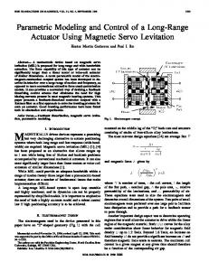
Fig. 5.
The
mth-order B-spline basis for m = 0, 1, 2, and 3.
where we use the notation (24)
(22) where , , and are defined as in the Appendix. Then, the following theorem is valid. Theorem: If the control law is given as in (22), then the tracking error will be driven to zero exponentially. Proof: See the Appendix. C. Adaptive Fuzzy Hybrid Control According to Theorem 1, the control law will depend on the of . However, in practice, gain parameters they are very difficult to obtain, and if they are overestimated, then the system will be easily trapped in a limit-cycle condition for a time-delayed or slowly sampled control servo. Hence, an intelligent control methodology is needed. Here, we introduce an adaptive fuzzy control algorithm as an intelligent control solution. Let the actual control law be rewritten as follows:
The th-order B-spline type of membership function has the following properties. )th-order continuously differentiable func• It is an ( . tion, i.e., only for • It has local compact support, i.e., . for • . • It is symmetric with respect to the center point (zero point). • for . Based on the definition of the local compact support, the above property can be rewritten as
(23) is a linear PD type compensator and is the key where adaptive fuzzy compensator. Here, we denote the fuzzy conand consider the fuzzy troller two-input single-output controller , consisting of (MISO) fuzzy controllers, which are characterized by
for
,where
is an integer set, defined as follows:
(25) where
is the th fuzzy controller; and and (i.e., and ) are the th input fuzzy variables; , , , where is a positive integer, and where it can be set arbitrarily large to obtain large enough compact sets; and are some positive real numbers. Here, each of the membership functions is given as an th-order multiple dimension central B-spline function (as depicted in Fig. 5), the th dimension of which is defined as follows:
Then, the membership functions for the th fuzzy variable are defined as follows: (26) whose compact support is given as (27) , which implies that and . It is possible that , ; i.e., can simultaneously fall into several for some compact supports. The indices labeling those supports are for means that
and
Authorized licensed use limited to: IEEE Xplore. Downloaded on January 13, 2009 at 20:54 from IEEE Xplore. Restrictions apply.
330
IEEE TRANSACTIONS ON ROBOTICS AND AUTOMATION, VOL. 16, NO. 4, AUGUST 2000
equivalent to these in the definition of (25) and, hence, can be rewritten as
(28) is the union set of these compact supports, dewhere fined as follows: (29) is equivalent to . which means that From [19], we can represent the above fuzzy controllers as follows:
Fig. 6. The network implementation of adaptive fuzzy control.
where
(30) are integer indices, where is the parameter function,
is the fuzzy basis
and
, is a smooth function vector so as to make smooth and is regarded as a designated dead-zone range which can be arbitrarily set. is given as in (30), Proposition 2: If the fuzzy control law then there exists a class of fuzzy controllers which can satisfy expression (32). satProof: To prove this, we have to assure that isfies two properties, namely, (a) [i.e., ] and (b) , when (i.e., ) for , respectively, from variable structure control theory. in (30), when Proof of a): From the definition , it follows that
i.e.,
Furthermore, the proposed fuzzy controller (30) can be realized by means of a network implementation, as shown in Fig. 6. Define the th element of a new vector as follows: as or otherwise (i.e.,
)
(31)
so that
i.e., for
, respectively, where and are both integer sets. Then, the representation of the th fuzzy controller can be rewritten as follows:
for Here, we want to design
as
so as to satisfy the following: as if otherwise if otherwise
(32)
is always positive, the sign of Since . Hence, we set mined by that of and for . As a result, we can conclude that .
Authorized licensed use limited to: IEEE Xplore. Downloaded on January 13, 2009 at 20:54 from IEEE Xplore. Restrictions apply.
. can be deterfor for
HSU AND FU: ADAPTIVE FUZZY HYBRID POSITION/FORCE CONTROL
331
Proof of b): Given the following definitions for :
by setting equality:
, we will obtain the following infor
By virtue of the fact that Fig. 7. test.
Setup: (a) A-type robot arm and (b) the end effector for the deburring
Fig. 8.
Profile of burrs.
(33) for
and in the cases where derive the following result:
, we can
as for . This completes our proof. Now, we define the optimal parameter vector of the th fuzzy controller as follows:
Theorem 2: If the update law and the control law are given as in (35) and (36), then the tracking errors will asymptotically converge to a neighborhood of zero. Proof: If we substitute the control law into (11), then the dynamic equation can be rewritten as follows:
Define matrices (34) may not be available due to the complexity of , . Therefore, the following adaptive law for upwill be necessary so that the dating the parameters vector tracking error can be driven toward the dead-zone range:
, , and , and define a Lyapunov
. Furthermore, let function
(38)
However,
for
where so that
is as previously defined in (31),
(35)
is some positive constant. where as Finally, we design
(36) where of
and the th element is defined as follows: as otherwise.
(37)
Then, the following theorem states the condition under which the above-mentioned adaptive fuzzy control law will yield a satisfactory result.
By invoking Barbalat’s lemma, it can be easily verified that as . This result along with (31) implies that tracking errors are ultimately bounded within the designated intervals. This completes our proof. Remark: The fuzzy controller (30) with the adaptive law (35) has the following advantages.
Authorized licensed use limited to: IEEE Xplore. Downloaded on January 13, 2009 at 20:54 from IEEE Xplore. Restrictions apply.
332
IEEE TRANSACTIONS ON ROBOTICS AND AUTOMATION, VOL. 16, NO. 4, AUGUST 2000
Fig. 9. Position/force tracking error results.
• It is a locally weighted fuzzy controller: only rules supneed to be updated so that those ported by compact set rules will be locally weighted. • It is a smooth fuzzy controller: the fuzzy controller (30) can behave as a smooth controller if we can choose membership functions which are smooth high-order B-spline is sufficient to functions. In our case, the order make the controller smooth. Besides, the computational complexity of the fuzzy controller (30) is discussed as follows [15]. From the above remarks, there rules that need to be computed. Then, it can are only and the be verified that the time complexity is . space complexity is
Fig. 10.
Chamfering force error results.
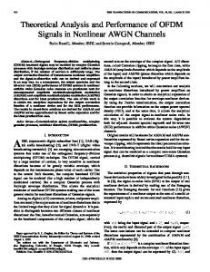
IV. EXAMPLE A five degree-of-freedom (DOF) articulated deburring robot arm equipped with a Zebra force sensor and a cutting tool (depicted in Fig. 7) is set up in the Intelligent Robot Laboratory with the Deptartment of Computer Science and Information Engineering at National Taiwan University. The deburring task is performed by controlling the robot arm to drive its cutting tool to chamfer the inner edge of the cylinder part, which has a 30-mm cross section radius as shown in Fig. 8. The same figure also shows the profile of burrs, which include three major burrs (height 1 mm) on the inner edge. The desired chamfer depth was set to 0.5 mm, and the desired champer force is set to 10 Nt. The control architecture based on an industrial PC has a 2.5-ms sampling period for the inner-loop hybrid controller and 25-ms sampling period for the outer-loop command generator. The cylinder is located on the table, expressed as and . To slow down mm/s [shown the speed of the contour-following, we set in expression (5)] and the average speed is about 2.4 mm/s. Furthermore, to reduce the number of fuzzy rules, the adaptive fuzzy controller is solely applied to control the position/force . We set the membership functions trajectory in the plane as a class consisting of the zeroth order and the second-order , , and B-spline basis with , where , , and are positive , , and into the inscaling factors used to normalize
terval , respectively. As a result, the fuzzy rule number . At the beginning, is equal to the initial parameter matrix is set to zero and updated to compensate for the uncertainties. and the normal contact force The champer depth error trajectory error are listed in Fig. 9 for the zeroth-order and the second-order B-spline membership functions, respectively. The chamfering force error and the surface finish result are given in Figs. 10 and 8. It is obvious that the adaptive fuzzy control implemented using the second-order B-spline membership functions has better performance. Figs. 11 and 12 show three-dimensional bar diagrams of the final parameters of the fuzzy controller after updating and three-dimensional plots of the control surface of the fuzzy controller with respect to the zeroth-order and the second-order B-spline membership functions. The fuzzy controller implemented using the second-order B-spline membership functions has a smoother control surface than does that implemented using the zeroth-order B-spline membership functions. To compare with the approach [2], the proposed controller not only has a better performance in the chamfering force and normal contact force but also yields a desired chamfer depth. V. CONCLUSIONS We have proposed an adaptive fuzzy hybrid position/force controller, which can update fuzzy rules to compensate for robot
Authorized licensed use limited to: IEEE Xplore. Downloaded on January 13, 2009 at 20:54 from IEEE Xplore. Restrictions apply.
HSU AND FU: ADAPTIVE FUZZY HYBRID POSITION/FORCE CONTROL
333
Fig. 11. Features of the zeroth-order B-spline based fuzzy controller.
dynamics along with the force dynamics induced by contact between a cutting tool and a part’s edge, and can identify the actual desired contact force. Besides, we showed the smooth fuzzy controller has a better performance than nonsmooth one. Finally, various control results have been provided to verify the effectiveness of the developed work.
A2)
, , for some positive constants
, and . Furthermore, we define the following control parameter: . D1) Then, , , and are defined as follows:
APPENDIX Before proceeding to solve Theorem 1, we summarize the properties of the system dynamics (1) as follows: for some positive constants
P1) and
; for some positive constants
P2) and
;
P3) holds for any vector ; and are denoted as a vector norm and a corwhere responding induced matrix norm, respectively. Besides these properties, to make the control problem contractible, we make the following assumptions: for some positive A1) and ; constants
Proof of Theorem 1: We set a Lyapunov function as and its time differential as follows:
Authorized licensed use limited to: IEEE Xplore. Downloaded on January 13, 2009 at 20:54 from IEEE Xplore. Restrictions apply.
334
Fig. 12.
IEEE TRANSACTIONS ON ROBOTICS AND AUTOMATION, VOL. 16, NO. 4, AUGUST 2000
Features of the second-order B-spline based fuzzy controller.
Based on the inequalities
we can get
REFERENCES [1] H. Kazerooni, J. J. Kramer, and B. M. , “An approach to automated deburring by robot manipulators,” J. Dynam. Syst. Meas. Contr., vol. 108, no. 4, pp. 354–359, Dec. 1986. [2] M. G. Her and H. Kazerooni, “Automated robotic deburring of parts using compliance control,” J. Dynam. Syst. Meas. Contr., vol. 113, pp. 60–66, March 1991. [3] H. Kazerooni, “On the robot compliant motion control,” J. Dynam. Syst. Meas. Contr., vol. 111, pp. 416–423, Sept. 1989. [4] S. Lu and H. Asada, “Transferring manipulative skills to robots: Representation and acquisition of tool manipulative skills using a process dynamics control,” J. Dynam. Syst. Meas. Contr., vol. 114, pp. 220–228, June 1992. [5] , “Teaching and learning of deburring robots using neural networks,” in Proc. 1993 IEEE Int. Conf. on Robotics and Automation, 1993, pp. 339–345. [6] K. Kiguchi and T. Fukuda, “Intelligent position/force controller for industrial robot manipulators—Application of fuzzy neural networks,” IEEE Trans. Ind. Electron., vol. 44, pp. 753–761, Dec. 1997. [7] G. M. Bone and M. A. Elbestawi, “Robotic force for deburring using an active end effector,” Robotica, vol. 7, pp. 303–308, 1989. [8] G. M. Bone, M. A. Elbestawi, R. Lingarkar, and l. Liu, “Force control for robotic deburring,” J. Dynam. Syst. Measure. Contr., vol. 113, pp. 395–400, Sept. 1991. [9] M. S. Ali, M. N. Noori, and J. Turi, “Automatic deburring utilizing a real-time impedance control strategy,” Comput. Structure, vol. 46, no. 3, pp. 561–571, 1993.
Authorized licensed use limited to: IEEE Xplore. Downloaded on January 13, 2009 at 20:54 from IEEE Xplore. Restrictions apply.
HSU AND FU: ADAPTIVE FUZZY HYBRID POSITION/FORCE CONTROL
[10] D. Jeon and M. Tomizuka, “Learning hybrid force and position control of robot manipulators,” IEEE Trans. Robot. Automat., vol. 9, pp. 423–432, Aug. 1993. [11] J. Marsden, Elementary Classical Analysis. San Franciso, CA: W. H. Freeman, 1974. [12] C. K. Chui, Wavelet Analysis and Its Application. Boston, MA: Academic, 1991, vol. 1, An Introduction to Wavelets, pp. 80–90. [13] J. J. Craig, Introduction to Robotics Mechanics and Control. Reading, MA: Addison-Wesley, 1989. [14] M. W. Spong and M. Vidyasagar, Robot Dynamics and Control. New York: Wiley, 1989. [15] J.-C. Latombe, Robot Motion Planning. Norwell, MA: Kluwer, 1991, pp. 599–602. [16] J.-J. E. Slotine and W. Li, Applied Nonlinear Control. Englewood Cliffs, NJ: Prentice-Hall, 1991, pp. 278–284. [17] R. M. Sanner and J.-J. E. Slotine, “Gaussian networks for direcet adaptive control,” IEEE Trans. Neural Networks, vol. 3, pp. 837–863, Nov. 1992. [18] S. Sastry and M. Bodson, Adaptive Control: Stability, Convergence, and Robustness. Englewood Cliffs, NJ: Prentice-Hall, 1989. [19] L.-X. Wang, Adaptive Fuzzy Systems and Control: Design and Stability Analysis. Englewood Cliffs, NJ: Prentice-Hall, 1994. [20] C. T. Lin and C. S. G. Lee, “Neural-network-based fuzzy logic control and decision systems,” IEEE Trans. Comput., vol. 40, no. 12, pp. 1320–1326, 1991. [21] H. T. Nguyen and V. Kreinovich, “On approximation of controls by fuzzy systems,” in Proc. 5th IFSA Congress, Seoul, Korea, 1996, pp. 1414–1417. [22] V. S. C. Raviraj and P. C. Sen, “Comparative study of proportional-integral, sliding mode, and fuzzy logic controllers for power converters,” IEEE Trans. Ind. Applicat., vol. 33, no. 2, pp. 518–524, 1997. [23] J. S. Glower and J. Muunighan, “Designing fuzzy controllers from a variable structures standpoint,” IEEE Trans. Fuzzy Syst., vol. 5, pp. 138–144, Feb. 1997. [24] S.-C. Lin and Y.-Y. Chen, “Design of self-learning fuzzy sliding mode controllers based on genetic algorithms,” Fuzzy Sets Syst., vol. 86, no. 2, pp. 139–153, Mar. 1997. [25] J. C. Wu and T. S. Liu, “Fuzzy control stabilization with applications to motorcycle control,” IEEE Trans. Syst., Man, Cybern. B, vol. 26, pp. 836–847, Dec. 1996. [26] F.-Y. Hsu and L.-C. Fu, “Adaptive robust fuzzy control for robot manipulators,” in Proc. IEEE Conf. on Robotics and Automation, 1994, pp. 629–634. , “A new design of adaptive fuzzy hybrid force/position controller [27] for robot manipulators,” in Proc. IEEE Conf. on Robotics and Automation, 1995, pp. 863–868. [28] , “Intelligent robot deburring using adaptive fuzzy hybrid control,” in Proc. 27th Int. Symp. on Industrial Robots, Milan, Italy, 1996, pp. 847–852.
335
Feng-Yi Hsu was born in Ping-Tung County, Taiwan, R.O.C., in 1969. He received the B.S. and M.S. degrees in aeronautical and astronautical engineering from National Cheng Kung University, in 1990 and 1992, respectively, and the Ph.D. degree in electrical engineering from National Taiwan University in 2000. From 1997 to 1999, he was with AverMedia Technologies, Inc., as a Senior Engineer. His areas of research interest include intelligent control and applications of robots, fuzzy control, and nonlinear control.
Li-Chen Fu (S’85–M’88) was born in Taipei, Taiwan, R.O.C., in 1959. He received the B.S. degree from National Taiwan University in 1981 and the M.S. and Ph.D. degrees from the University of California, Berkeley, in 1985 and1987, respectively. Since 1987, he has been on the faculty and is currently is a Professor of both the Department of Electrical Engineering and the Department of Computer Science and Information Engineering, National Taiwan University. He now also serves as the Deputy Director of Tjing Ling Industrial Research Institute of National Taiwan University. His areas of research interest include adaptive control, nonlinear control, induction motor control, visual tracking, control of robots, FMS scheduling, and shop floor control. Dr. Fu is now a member of both the IEEE Robotics and Automation Society and the IEEE Automatic Control Society. From 1996 to 1998, he was appointed a Member of AdCom of IEEE Robotics and Automation Society, and will serve as the Program Chair of 2003 IEEE International Conference on Robotics and Automation. He is also a Board Member of the Chinese Automatic Control Society and the Chinese Institute of Automation Engineers. He has been the Editor of Journal of Control and Systems Technology and is currently an Associate Editor of the prestigious control journal, Automatica. Starting in 1999, he became Editor-in-Chief of a new control journal, called Asian Journal of Control. Dr. Fu received the Excellent Research Award in the period of 1990–1993 and Outstanding Research Awards in the years of 1995 and 1998 from National Science Council, R.O.C., respectively, the Outstanding youth Medal in l991, the Outstanding Engineering Professor Award in l995, the Best Teaching Award in 1994 from Ministry of Education, and The Ten Outstanding Young Persons Award in 1999 of R.O.C.
Authorized licensed use limited to: IEEE Xplore. Downloaded on January 13, 2009 at 20:54 from IEEE Xplore. Restrictions apply.