electronics Article
Robust and Accurate Algorithm for Wearable Stereoscopic Augmented Reality with Three Indistinguishable Markers Fabrizio Cutolo 1, *, Cinzia Freschi 1 , Stefano Mascioli 1 , Paolo D. Parchi 1,2 , Mauro Ferrari 1,3 and Vincenzo Ferrari 1,3,4 1
2 3 4
*
EndoCAS Center, Department of Translational Research and New Technologies in Medicine and Surgery, University of Pisa, Pisa 56124, Italy;
[email protected] (C.F.);
[email protected] (S.M.);
[email protected] (P.D.P.);
[email protected] (M.F.);
[email protected] (V.F.) 1st Orthopedic Division, University of Pisa, Pisa 56125, Italy Vascular Surgery Unit, Azienda Ospedaliero Universitaria Pisana, Pisa 56126, Italy Information Engineering Department, University of Pisa, Pisa 56122, Italy Correspondence:
[email protected]; Tel.: +39-050-995-689; Fax: +39-050-992-773
Academic Editors: Enzo Pasquale Scilingo and Gaetano Valenza Received: 18 May 2016; Accepted: 9 September 2016; Published: 19 September 2016
Abstract: In the context of surgical navigation systems based on augmented reality (AR), the key challenge is to ensure the highest degree of realism in merging computer-generated elements with live views of the surgical scene. This paper presents an algorithm suited for wearable stereoscopic augmented reality video see-through systems for use in a clinical scenario. A video-based tracking solution is proposed that relies on stereo localization of three monochromatic markers rigidly constrained to the scene. A PnP-based optimization step is introduced to refine separately the pose of the two cameras. Video-based tracking methods using monochromatic markers are robust to non-controllable and/or inconsistent lighting conditions. The two-stage camera pose estimation algorithm provides sub-pixel registration accuracy. From a technological and an ergonomic standpoint, the proposed approach represents an effective solution to the implementation of wearable AR-based surgical navigation systems wherever rigid anatomies are involved. Keywords: augmented reality; wearable displays; image-guided surgery; machine vision; camera calibration
1. Introduction Augmented reality (AR) [1] is a ground-breaking technology in machine vision and computer graphics and may open the way for significant technological developments in the context of image-guided surgery (IGS). In AR-based applications, the key challenge is to ensure the highest degree of realism in merging computer-generated elements with live views of the surgical scene. AR in IGS allows merging of real views of the patient with computer-generated elements generally consisting of patient-specific three-dimensional (3D) models of anatomy extracted from medical datasets (Figure 1). In this way, AR establishes a functional and ergonomic integration between surgical navigation and virtual planning by providing physicians with a virtual navigation aid contextually blended within the real surgical scenario [2]. In recent years, there has been a growing research interest in AR in medicine, which has driven a remarkable increase in the number of published papers. A PubMed search was performed of publications with the terms “augmented reality” OR “mixed reality” in the title or abstract. The first publication dated back to 1995 [3]. After 13 years, on 31 December 2008, the number of publications reached 255. During the last seven years, between 1 January 2009 and 30 April 2016, 647 papers were Electronics 2016, 5, 59; doi:10.3390/electronics5030059
www.mdpi.com/journal/electronics
Electronics 2016, 5, 59 Electronics 2016, 5, 59
2 of 18 2 of 18
reached 255. During the last seven years, between 1 January 2009 and 30 April 2016, 647 papers were published, 168 of them in the past year. Nonetheless, only a few of the reported publications dealt published, of them of in the the technology past year. Nonetheless, onlyeven a few of the reported its publications dealt with with clinical168 validation described, and fewer addressed in vivo assessment. clinical validation of the technology described, and even fewer addressed its in vivo assessment. This is mostly due to the technological barriers encountered in the attempt to integrate similar This AR is mostly duethe to surgical the technological barriers encountered in the attempt to integrate similar AR systems systems into workflow. into Based the surgical workflow. on these considerations, the present work is aimed at developing strategies that could Based on these presentAR work is aimed at developing facilitate the profitableconsiderations, introduction ofthe wearable systems to clinical practice. strategies that could facilitate the profitable introduction of wearable AR systems to clinical practice.
Figure 1. Augmented Reality video see-through paradigm: the 2D virtual image (heart) is mixed into Figure 1. Augmented video see-through the 2D virtual image (heart) is mixed into an image frame of theReality real world grabbed by theparadigm: external camera. an image frame of the real world grabbed by the external camera.
In the realm of AR-based IGS systems, various display technologies have been proposed. In light In the realm of AR-based IGS systems, various display technologies have been proposed. In light of avoiding abrupt changes to the surgical setup and workflow, historically the first AR-based surgical of avoiding abrupt changes to the surgical setup and workflow, historically the first AR-based navigation systems were implemented on the basis of commonly used devices [4] such as surgical surgical navigation systems were implemented on the basis of commonly used devices [4] such as microscopes [5,6]. In laparoscopy, and generally in endoscopic surgery, the part of the environment surgical microscopes [5,6]. In laparoscopy, and generally in endoscopic surgery, the part of the where the surgeon’s attention is focused during the surgical task (DVV’s Perception Location [7]) is a environment where the surgeon’s attention is focused during the surgical task (DVV’s Perception stand-up monitor. Indeed, in such procedures, the surgeon operates watching endoscopic video images Location [7]) is a stand-up monitor. Indeed, in such procedures, the surgeon operates watching reproduced on the spatial display unit [8,9]. Therefore, the virtual information is usually merged with endoscopic video images reproduced on the spatial display unit [8,9]. Therefore, the virtual real-time video frames grabbed by the endoscope and presented on a stand-up monitor [10–12]. information is usually merged with real-time video frames grabbed by the endoscope and presented Alternative and promising approaches based on integral imaging (II) technology have been on a stand-up monitor [10–12]. proposed [13,14]. II displays use a set of 2D elemental images from different perspectives to generate Alternative and promising approaches based on integral imaging (II) technology have been a full-parallax 3D visualization. Therefore, with II-based displays, a proper 3D overlay between proposed [13,14]. II displays use a set of 2D elemental images from different perspectives to generate virtual content and a real scene can be obtained. Certain embodiments of this technology have been a full-parallax 3D visualization. Therefore, with II-based displays, a proper 3D overlay between specifically designed and tested for maxillofacial surgery and neurosurgery [15–19]. The II paradigm virtual content and a real scene can be obtained. Certain embodiments of this technology have been can provide the user with an egocentric viewpoint and a full-parallax augmented view in a limited specifically designed and tested for maxillofacial surgery and neurosurgery [15–19]. The II paradigm viewing zone (imposed by the II display). However, wearable embodiments of II technology still can provide the user with an egocentric viewpoint and a full-parallax augmented view in a limited require further development of both hardware and software aspects [20]. viewing zone (imposed by the II display). However, wearable embodiments of II technology still In general, the quality of an augmented reality (AR) experience, particularly in IGS systems, require further development of both hardware and software aspects [20]. depends on how well the virtual content is blended with the surgical scene spatially, photometrically, In general, the quality of an augmented reality (AR) experience, particularly in IGS systems, and temporally [21]. In this regard, wearable AR systems offer the most ergonomic solution in depends on how well the virtual content is blended with the surgical scene spatially, photometrically, those medical tasks that are manually performed under the surgeon’s direct vision (open surgery, and temporally [21]. In this regard, wearable AR systems offer the most ergonomic solution in those introduction of biopsy needle, palpation, etc.) because they minimize the extra mental effort required medical tasks that are manually performed under the surgeon’s direct vision (open surgery, to switch focus between the real surgical task and the augmented view presented on the external introduction of biopsy needle, palpation, etc.) because they minimize the extra mental effort required display. Wearable AR systems based on head-mounted displays (HMDs) intrinsically provide the to switch focus between the real surgical task and the augmented view presented on the external user with an egocentric viewpoint and do not limit freedom of movement around the patient [22–24]. display. Wearable AR systems based on head-mounted displays (HMDs) intrinsically provide the Standard HMDs provide both binocular parallax and motion parallax and smoothly augment the user with an egocentric viewpoint and do not limit freedom of movement around the patient [22–24]. user’s perception of the surgical scene throughout the specific surgical procedure. At present, they are Standard HMDs provide both binocular parallax and motion parallax and smoothly augment the less obtrusive in the operating room (OR) than II systems. In HMDs, the see-through capability is user’s perception of the surgical scene throughout the specific surgical procedure. At present, they provided through either a video or an optical see-through paradigm.
Electronics 2016, 5, 59
3 of 18
Typically, in optical see-through HMD systems, the user’s direct view is augmented by the projection of virtual information either on semi-transparent displays placed in front of the eyes or directly onto the retina [25]. Accurate alignment between the direct view of the real scene and the virtual information is provided by real-time tracking of the visor and user-specific calibration that accounts for the change in relative position and orientation (pose) between display and eyes each time the user wears or moves the HMD [26,27]. Display-eye calibration is necessary to model intrinsically and extrinsically the virtual view frustum to the user’s real one [28]. The video see-through solution is instead based on external cameras rigidly fixed in front of the HMD. In these systems, although the field of view is limited by the size of the camera optics and displays, a user-specific calibration routine is not necessary. Furthermore, in video see-through systems, the real scene and the virtual information can be synchronized, whereas in optical see-through devices, there is an intrinsic lag between immediate perception of the real scene and inclusion of the virtual elements. Therefore, at the current technological level, the use of video see-through systems is immediate, at least for those IGS applications that can tolerate slight delays between capture of the real scene by the cameras and its final presentation in augmented form. Accurate alignment between the real scene and the virtual content is provided by tracking the HMD in relation to the real world (represented by matrix SRS TCRS in Figure 1), which is usually performed by means of an external tracker [29]. In a previous work, we presented an early system based on a commercially available HMD equipped with two external cameras aligned to the user’s eyes [23]. The see-through ability was created by combining 3D computer-generated models obtained by processing radiological images (e.g., CT or MRI) [30] with live views of the real patient. The distinctive feature of that AR system was that the pair of external cameras served both to capture the real scene and to perform stereo tracking. As the authors, we share the conviction that the absence of an external tracker is a key element in enabling smooth and profitable integration of AR systems into the surgical workflow. Surgical navigation systems based on external infrared trackers have the major drawback of introducing unwanted line-of-sight constraints into the OR and of adding error-prone technical complexity to the surgical procedure [29]. Other tracking modalities are based on more complex surface-based tracking algorithms [12,31]. As an alternative to optical tracking, electromagnetic tracking systems are particularly suited for tracking hidden structures [32], but their accuracy and reliability are severely affected by the presence of ferromagnetic and/or conductive materials [33]. Standard video-based tracking methods featuring the use of large template-based markers provide highly accurate results in non-stereoscopic systems. Nonetheless, they are not suited for use in a surgical setting because they limit the surgeon’s line of sight given their planar structure and they may occlude the visibility of the operating field. In that early system, and as previously done in [10,34], real-time registration of the virtual content to the real images was achieved by localizing chromatically distinguishable spherical markers. The video marker-based registration method registers the virtual 3D space to the camera coordinate system (CRS) through real-time determination of the camera pose in the radiological coordinate system (SRS). Small spherical markers do not seriously affect the line of sight and can be conveniently placed on the patient’s skin with minimal logistic impact on the surgical workflow. With the objective of increasing system usability, the minimum set of markers (i.e., three) that could ensure a finite number of solutions to the camera pose estimation problem was chosen. The chromatic differences among the three markers and the stereo-camera setup enabled solution of the stereo correspondence problem and real-time computation of camera pose without the ambiguity of the general perspective-3-point (P3P) problem [35]. In practice, thanks to stereo tracking, the camera pose estimation problem can be reduced to determining the standard closed-form least-squares solution of the absolute orientation problem (AOP) given a set of three correspondences in the two 3D coordinate systems (CRS and SRS) [36]. The coordinates of the three markers in the CRS were recovered by applying stereo localization routines to the pairs of conjugate projections of the marker centroids taken from the image planes of
Electronics 2016, 5, 59
4 of 18
the two cameras. Image coordinates of the marker centroids were determined by performing a feature extraction task using color segmentation and circular shape recognition. Hence, in the early system, robust feature extraction was crucial to providing accurate geometric registration. Unfortunately, the shortcomings of the earlier approach were twofold: the non-fully controllable and/or inconsistent lighting conditions in the OR, and the intrinsic difficulty of robustly classifying three different colors using a standard thresholding technique. These shortcomings cannot be neglected if the system is to be integrated into the surgical workflow. Adoption of stringent thresholding criteria in the segmentation step may in fact result in inconsistent target identification because the connected regions tend to be poorly segmented. On the contrary, large thresholds may generate badly segmented regions or yield incorrect markers labelling. In the present work, we shall present a tracking-by-detection solution that uses monochromatic markers and new marker labeling strategies to increase the robustness of the video-based tracking method under non-controllable lighting conditions. In addition, the proposed solution overcomes another limitation of the earlier algorithm. As mentioned above, the 3D position of the markers in the CRS is estimated through stereoscopic triangulation routines applied to pairs of images acquired by the two external cameras. Nevertheless, the anthropomorphic geometry of the stereo setup can ensure adequate marker localization accuracy only at close distances. This localization error is inherent to the stereoscopic geometry and depends on the accuracy of the disparity estimate in the proposed feature extraction procedure and on the calibration errors in estimating the intrinsic and extrinsic camera parameters [37]. In Section 2.2.2, an example of such inaccuracy due to the anthropomorphic geometry of the stereo setup is reported. To cope with this limitation in this work we added a PnP-based optimization step, which refines the pose of both cameras separately and yields sub-pixel registration accuracy in the image plane. Another interesting landmark-based mono-camera tracking solution has been proposed by Schneider et al. [38]. Their approach, based on an efficient and innovative 2D/3D point pattern matching algorithm, was specifically designed for computationally low-power devices and was proven to yield good results in terms of image registration accuracy and computational performance. Compared to that solution, our method needs fewer reference landmarks (i.e., three), whereas their single-view approach for estimating the camera pose cannot work if fewer than six landmarks can be seen. Use of a minimum set of three fiducial markers is in fact intended to limit the logistic payload for setup, and this aspect is key for facilitating the smooth integration of the system into the surgical workflow. The proposed solution tackles the ambiguity of the P3P problem through the stereoscopic settings of the video see-through system. To the best of the authors’ knowledge, no previous work in AR has addressed the image-to-patient registration problem and has achieved sub-pixel registration accuracy through a video marker-based method that uses only three chromatically indistinguishable markers. 2. Materials and Methods This section is organized as follows. Section 2.1 provides a detailed description of the hardware and of the software libraries used to implement the proposed stereoscopic AR mechanism. Section 2.2 describes the new methods used to solve marker labeling and to obtain a first estimate of the camera pose in relation to the SRS. The same subsection also describes the optimization method that solves the perspective-3-point (P3P) problem and yields sub-pixel registration accuracy in the image plane. Finally, Section 2.3 explains the methodology used to evaluate registration accuracy. 2.1. System Overview The aim of this work is to present a robust and accurate video-based tracking method suited for use in a clinical scenario. The solution is based on tracking three indistinguishable markers. The algorithm was developed for a HMD AR system, but it could be applied to other stereoscopic devices like binocular endoscopes or binocular microscopes. Reference hardware has been chosen to achieve a
Electronics 2016, 5, 59 Electronics 2016, 5, 59
5 of 18 5 of 18
a low-cost system assembling off-the-shelf components manufacturing custom-made parts. low-cost system byby assembling off-the-shelf components andand manufacturing custom-made parts. The The custom-made see-through was from madea from a Z800 visor (eMagin, custom-made videovideo see-through HMD HMD was made Z800 3D visor3D (eMagin, HopewellHopewell Junction, Junction, USA)2).(Figure 2). The HMD is provided with dualpanels OLEDand panels and features a diagonal NY, USA)NY, (Figure The HMD is provided with dual OLED features a diagonal field of field of viewof(FoV) view (FoV) 40◦ . of 40°.
Figure 2.2.Video Videosee-through see-through head-mounted display (HMD) obtained by mounting two external Figure head-mounted display (HMD) obtained by mounting two external cameras cameras top of a commercial on top ofon a commercial 3D visor. 3D visor.
A plastic frame (ABS) was built through rapid prototyping to act as a support for the two A plastic frame (ABS) was built through rapid prototyping to act as a support for the two external external USB cameras equipped with 1/3′′ image sensors UI-1646LE (IDS, Imaging Development USB cameras equipped with 1/300 image sensors UI-1646LE (IDS, Imaging Development Systems Systems GmbH, Obersulm, Germany). By means of this support, the two cameras are mounted GmbH, Obersulm, Germany). By means of this support, the two cameras are mounted parallel to each parallel to each other with an anthropometric interaxial distance ( ~7 cm) to provide a quasiother with an anthropometric interaxial distance (∼7 cm) to provide a quasi-orthoscopic view of the orthoscopic view of the augmented scene mediated by the visor. When the user looks at the real augmented scene mediated by the visor. When the user looks at the real world while wearing the world while wearing the HMD, there are no appreciable differences between natural and visorHMD, there are no appreciable differences between natural and visor-mediated views [39]. mediated views [39]. A toed-in camera configuration would be preferable for achieving better stereo overlap at close A toed-in camera configuration would be preferable for achieving better stereo overlap at close working distances, but if not coupled with simultaneous convergence of the optical display axes, working distances, but if not coupled with simultaneous convergence of the optical display axes, this this would go against the objective of this work: achievement of a quasi-orthostereoscopic AR HMD. would go against the objective of this work: achievement of a quasi-orthostereoscopic AR HMD. As As a matter of fact, another study by the authors has presented a different video see-through HMD that a matter of fact, another study by the authors has presented a different video see-through HMD that features the possibility of adjusting the degree of convergence of the stereo camera pair as a function features the possibility of adjusting the degree of convergence of the stereo camera pair as a function of the working distance [40]. of the working distance [40]. The Z800 HMD receives video frames from the computer via VGA cable and alternately transmits The Z800 HMD receives video frames from the computer via VGA cable and alternately them to left and right internal monitors at 60 Hz in sync with the vsync signal. Therefore, the software, transmits them to left and right internal monitors at 60 Hz in sync with the vsync signal. Therefore, which renders and mixes the virtual model with the real frames, must set up and exchange left and the the software, which renders and mixes the virtual model with the real frames, must set up and right views synchronously with the vsync signal as well. The proposed software application elaborates exchange left and the right views synchronously with the vsync signal as well. The proposed software the grabbed video frames to perform real-time registration. Due to the computational complexity of application elaborates the grabbed video frames to perform real-time registration. Due to the the whole video see-through paradigm, a multithreaded application was implemented to distribute computational complexity of the whole video see-through paradigm, a multithreaded application the operations among available processors to guarantee synchronization of the two views to be sent was implemented to distribute the operations among available processors to guarantee to the HMD. One thread sets up the AR views and ensures their synchronization, whereas the other synchronization of the two views to be sent to the HMD. One thread sets up the AR views and ensures performs video-based tracking. their synchronization, whereas the other performs video-based tracking. A synthetic functional and logical description of the AR mechanism is as follows: real cameras A synthetic functional and logical description of the AR mechanism is as follows: real cameras grab video frames of the scene; video frames, after radial distortion compensation, are screened grab video frames of the scene; video frames, after radial distortion compensation, are screened as as backgrounds of the corresponding visor display; virtual anatomies, reconstructed offline from backgrounds of the corresponding visor display; virtual anatomies, reconstructed offline from radiological images, are coherently merged to create the augmented scene. For coherent merging radiological images, are coherently merged to create the augmented scene. For coherent merging of of real scenes and virtual content, the virtual content is observed by a couple of virtual viewpoints real scenes and virtual content, the virtual content is observed by a couple of virtual viewpoints (virtual cameras) with projective parameters that mimic those of the real cameras and with poses that (virtual cameras) with projective parameters that mimic those of the real cameras and with poses that vary according to the real-time marker-based tracking method (Figure 3). vary according to the real-time marker-based tracking method (Figure 3). This AR mechanism was implemented in software libraries built in C++ on top of the multipurpose EndoCAS Navigator Platform modules [41]. Management of the virtual 3D scene was
carried out through the OpenSG 1.8 open-source software framework (www.opensg.org). As for the machine vision routines needed to implement the video-based tracking method, the Halcon 7.1 library (MVTec Software Gmbh, Munich, Germany, 2008) was used. The whole application was implemented to be compatible with several 3D displays (working either with side-by-side or alternate frames) and with all cameras for which DirectShow drivers by Microsoft are available. The Electronics 2016, 5, 59 6 of 18 configurable software framework is described in more detail in [42].
Figure registrationalgorithm. algorithm. Figure3.3.Localization Localization and and registration
In AR a video see-through system, to achieve an accurate and robust fusion between reality and This mechanism was implemented in software libraries built in C++ on top of the multipurpose virtuality, the virtualPlatform scene must be rendered that the following conditions arewas satisfied: EndoCAS Navigator modules [41]. so Management of thethree virtual 3D scene carried out through thevirtual OpenSG 1.8 open-source software framework 1. The camera projection models ≈ to the real ones. (www.opensg.org). As for the machine vision needed implement the virtual video-based tracking method, the≈Halcon 7.1 one. library (MVTec 2. routines The relative posetobetween the two cameras of the stereo setup to the real Software Germany, 2008) wastools used.≈ to The application was implemented to 3. TheGmbh, pose ofMunich, the virtual anatomies/surgical thewhole real ones. be compatible with several 3D displays (working either with side-by-side or alternate frames) and The first condition implies that the virtual camera viewing frustums are to be modeled on the with all cameras for which DirectShow available. The configurable real ones in terms of image size, focusdrivers length, by andMicrosoft center of are projection (intrinsic calibration). software At the framework is the described in more detail in that [42].the relative pose between the two virtual cameras of the same time, second condition implies In a setup videomust see-through system, achieve an the accurate and robust(extrinsic fusion between reality and stereo be set equal to the to pose between two real cameras calibration). virtuality, the two virtual scene must be rendered so that theoffline following three conditions are satisfied: These calibration routines can be performed by implementing Zhang’s calibration routine [43] (in this research, Halcon libraries were used for this task). The nonlinear part of the 1. The virtual camera projection models ≈ to the real ones. internal camera model (due to lens radial distortion) was taken into account by compensating for the 2. distortion The relative pose between the two virtual cameras of the setup ≈ to of thethe real over the grabbed images before rendering them ontostereo the background leftone. and right 3. visor Thedisplays. pose of the virtual anatomies/surgical tools ≈ to the real ones.
The first condition implies that the virtual camera viewing frustums are to be modeled on the real ones in terms of image size, focus length, and center of projection (intrinsic calibration). At the same time, the second condition implies that the relative pose between the two virtual cameras of the stereo setup must be set equal to the pose between the two real cameras (extrinsic calibration). These two calibration routines can be performed offline by implementing Zhang’s calibration routine [43] (in this research, Halcon libraries were used for this task). The nonlinear part of the internal camera model (due to lens radial distortion) was taken into account by compensating for the distortion over the grabbed images before rendering them onto the background of the left and right visor displays.
Electronics 2016, 5, 59
7 of 18
Finally, the pose of the virtual elements in the virtual scene must be set equal to the real pose between the real anatomies/tools and the physical camera. This latest condition was satisfied by using a video marker-based tracking method that will be described in the following subsections. 2.2. 3D Localization and Tracking Algorithm The poses of the two cameras relative to the anatomy and vice versa are determined by tracking passive colored markers constrained to the surgical scene in defined positions. The proposed video-based tracking solution relies on stereo localization of three monochromatic markers and is robust to inconsistent lighting conditions. 3D coordinates of the markers in the left CRS are retrieved by applying stereo 3D Localization routines on pairs of conjugate projections of the markers’ centroids onto the image planes of the two cameras. Image coordinates of the marker centroids are determined by a feature extraction task performed using Color Segmentation and Circular Shape Recognition. 2.2.1. Feature Extraction, Stereo Correspondence, and Marker Labeling As an overall concept, color segmentation based on thresholding must ensure a robust tradeoff between illumination invariance and absence of segmentation overlaps among differently colored regions. Adoption of stringent thresholding criteria may result in inconsistent target identification because the connected regions may be poorly segmented. On the contrary, large thresholds may generate badly segmented regions or yield incorrect marker labeling in the case of multicolored markers. This drawback is emphasized by the use of cheap and/or small cameras equipped with Bayer filter color sensors. Such sensors provide inferior color quality and lower signal-to-noise ratio than those based on three sensors and a trichroic beam splitter prism for each pixel (3-CCD sensing). Use of monochromatic markers makes it possible to achieve higher robustness in the Feature Extraction step and in the presence of non-controllable and inconsistent lighting conditions because incorrect labelling is intrinsically avoided. To cope partially with the limitation of using visible light as an information source, Color Segmentation was performed in the HSV (hue, saturation, value) color space. HSV is a human-oriented representation of the distribution of the electromagnetic radiation energy spectrum [44]. HSV enables a sufficiently robust segmentation of objects that undergo non-uniform levels of illumination intensity, shadows, and shading [45,46]. The assumption is that light intensity primarily affects the value (V) channel, whereas the hue (H), and to a lesser extent the saturation (S) channels are less influenced by illumination changes [46]. The chromatic choice for the markers must lean towards highly saturated colors, as was done in [47]. In this way, segmentation based on thresholding becomes more selective: it can be performed with a high cutoff value in the S-channel. After Color Segmentation, three broader connected regions with a circular shape factor >0.5 are identified on both images. Then, the centroids of the selected regions are determined. These image points correspond to the projections of the marker centroids on the image planes of the two cameras. Figure 4 shows the results of Color Segmentation. After Circular Shape Recognition, the 2D projections of the three marker centroids on the left and right images are known. The Stereo Correspondence problem is solved with a method based on minimizing an energy term computed by applying standard projective rules to all possible permutations of matches between the feature-point triplets on the image pair. In more detail, knowing the internal parameters and the relative pose between the two cameras, it is possible to determine the 3D position of a point from its projections on the left and right cameras (stereo triangulation). The 3D position of the point in the CRS can be approximated as the middle of the shortest segment joining the two projection lines. The distance between the two projection lines (DPL) is correlated with the localization error and depends on working distance, inter-camera distance, calibration quality, and identification accuracy of the conjugate image points. By working with a set of indistinguishable markers, it is not possible to localize the markers in the CRS without ambiguity because the correspondence between projected points on the left and right cameras (known as conjugate points) is unknown. The algorithm calculates
Electronics 2016, 5, 59
8 of 18
the position of the three marker centroids together with the associated DPL for each of the six possible Electronics 2016, 5, 59 8 of 18 permutations of possible conjugate point matches. Hence, the solution for the stereo correspondence is assumed to be the one that minimizes the sum of theover threethe DPLs the problemcorrespondence is assumed be the one that minimizes the sum of the three DPLs sixover permutations. Electronics 2016, 5, to 59problem 8 of 18 permutations. Once thehas right correspondence determined, positions of centroids the three in the Once thesixright correspondence been determined,has thebeen positions of thethe three marker correspondence is assumed to be thethe oneStereo that minimizes the sum of3D theLocalization three DPLssteps over are the in the CRS are given, and Correspondence CRS aremarker given,centroids and theproblem Stereo Correspondence and 3D Localization stepsand are complete. six permutations. Once the right correspondence has been determined, the positions of the three complete. Figure 5 shows theinresults of thegiven, Stereoand Correspondence step on a pair 3D of sample images. Note that marker centroids theresults CRS are the Stereo Correspondence Localization stepsthat are Figure 5 shows the of the Stereo Correspondence step on a pairand of sample images. Note after thisafter step, the correspondence between each of the projected marker centroids on the two complete. this step, the correspondence between each of the projected marker centroids on the two images images is known, but thebut labels (i.e., thethe 3D-3D Correspondence) remain Figure 5marker shows the results of(i.e., the Stereo Correspondence step on a pairunknown. ofunknown. sample images. Note that is known, the marker labels 3D-3D Correspondence) remain after this step, the correspondence between each of the projected marker centroids on the two images is known, but the marker labels (i.e., the 3D-3D Correspondence) remain unknown.
Figure 4. Results of the Color Segmentation and Circular Shape Recognition steps. In the first row, left
Figure 4.and Results of the Color Segmentation and Circular Shape Recognition steps. In the first row, left and right camera native frames are shown. The second row shows the results of Color Segmentation, right camera native frames are shown. The second rowRecognition. shows the resultssteps. of Color Segmentation, Figure Results of the Color Segmentation andShape Circular Shape Recognition In the first row, leftand the and the4.third row shows the results of Circular third row shows the results of Circular Shape Recognition. and right camera native frames are shown. The second row shows the results of Color Segmentation, and the third row shows the results of Circular Shape Recognition.
Figure 5. Stereo Correspondence: The correspondence between the three points on the left and right images is solved using multiple stereoscopic triangulation routines on the six possible permutations of the three points. In the images, the correct correspondences between the three points are shown.
Electronics 2016, 5, 59
9 of 18
Figure 5. Stereo Correspondence: The correspondence between the three points on the left and right images is solved using multiple stereoscopic triangulation routines on the six possible permutations Electronics 2016, 5, 59points. In the images, the correct correspondences between the three points are shown. 9 of 18 of the three
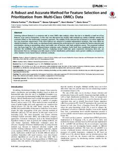
Therefore, before solving the registration problem, the 3D-3D Correspondence problem must be Therefore, before solving the registration problem, the 3D-3D Correspondence problem must be determined, which involves finding the proper set of corresponding points in the CRS and SRS. The determined, which involves finding the proper set of corresponding points in the CRS and SRS. 3D-3D Correspondence between the two sets of 3D points is solved by a geometric procedure that takes The 3D-3D Correspondence between the two sets of 3D points is solved by a geometric procedure that account of the similarity of the triangles formed by such points. This approach requires that the takes account of the similarity of the triangles formed by such points. This approach requires that the distances between markers not be equal. distances between markers not be equal. 2.2.2. Two-Stage Pose Estimation 2.2.2. Two-Stage Pose Estimation The rigid transformation between the two reference systems, namely the camera pose and the The rigid transformation between the two reference systems, namely the camera pose and the . Pose estimation is performed using a two-stage method, with the SRS, is encapsulated by matrix R|T SRS, is encapsulated by matrix R T . Pose estimation is performed using a two-stage method, with first step being solving the AOP by standard 3D Least-Squares Fitting of the two point sets through the first step being solving the AOP by standard 3D Least-Squares Fitting of the two point sets through SVD [36]. Figure 6 shows the visual results of the first registration step between the two reference SVD [36]. Figure 6 shows the visual results of the first registration step between the two reference systems. As shown in the figure, due to stereo localization inaccuracies, the image registration systems. As shown in the figure, due to stereo localization inaccuracies, the image registration resulting resulting from the AOP solution may be inaccurate. from the AOP solution may be inaccurate.
Figure6. 6. Geometric Geometric registration registration through through SVD: SVD: Geometric Geometricregistration registrationsolved solvedby byaa Least-Squares Least-SquaresFitting Fitting Figure method that provides a first rough alignment between the virtual information and the real scene. As method that provides a first rough alignment between the virtual information and the real scene. shown in in thethe first row, sufficiently accurate accurate As shown first row,atatclose closedistances distances(about (about40 40cm), cm),geometric geometric registration registration is sufficiently inthe thepresence presenceofofcalibrated calibrated cameras and with reliable disparity estimates. As shown the second in cameras and with reliable disparity estimates. As shown in theinsecond row, row, far the from the (~100 scenecm), (~100 cm), alignment rapidly degrades. row shows a far from scene alignment accuracyaccuracy rapidly degrades. The thirdThe rowthird shows a zoomed zoomed detail of the second row. detail of the second row.
Because of the geometry of the stereo setup, the limited focal length, and the degradation of the stereo camera calibration, adequate accuracy of 3D Localization of the markers at greater distances
Electronics 2016, 5, 59
10 of 18
cannot be ensured. The major error component in 3D Localization is along the optical axis (z-axis) and increases with the square of the distance. The depth resolution is calculated as in [37,48]: ∆Z ∼ =
z2 ∆d. fb
(1)
As an example, let us assume that we have determined a fixed and ideally error-free estimate of the focal length and the baseline (in the described system, f ∼ = 4.8 mm, b ∼ = 70 mm). Given a disparity accuracy of ±1 pixel and a sensor diagonal of 1/3” (∆d ∼ = 7.2 µm), the depth resolution ∆Z is approximately ±5 mm at a working distance of 50 cm. At 100 cm, this error increases to approximately ±21 mm (see the last row of Figure 6). Therefore, because of data noise and the geometry of the stereo setup, the SVD solution of the AOP cannot yield a sufficiently accurate result in terms of geometric registration. On this basis, this paper proposes a methodology for refining the estimates of both camera poses to increase the accuracy of the video-based tracking technique. The general problem of determining the pose of a calibrated camera with respect to a scene or object given its intrinsic parameters and a set of n world-to-image point correspondences was first formally introduced in the computer vision community by Fishler and Bolles in 1981 [49] using the term “Perspective-n-Point” problem (PnP). The PnP problem pertains to several areas of interest and is key to many fields like computer vision, robotics, and photogrammetry. In the transformation-based definition given in [49], the PnP problem aims to estimate the camera pose given a set of correspondences between n 3D points (known as “control points”) and their 2D projections in the image plane [50]. If the number of corresponding points is