Robust and Accurate Localization System for Mobile Manipulators in Cluttered Environments Carlos M. Costa, Héber M. Sobreira, Armando J. Sousa, Germano M. Veiga Centre for Robotics and Intelligent Systems INESC TEC (formerly INESC Porto) and Faculty of Engineering, University of Porto Porto, Portugal {carlos.m.costa,heber.m.sobreira}@inesctec.pt,
[email protected],
[email protected] Abstract—Autonomous robots play a pivotal role in improving productivity and reducing operational costs. They excel at both precision and speed in repetitive jobs and can cooperate with humans in complex tasks within dynamic environments. Selflocalization is critical to any robot that must navigate or manipulate the environment. To solve this problem, a modular localization system suitable for mobile manipulators was developed. By using LIDAR data the proposed system is capable of achieving less than a centimeter in translation error and less than a degree in rotation error while requiring only 5 to 25 milliseconds of processing time. The system was tested in two different robot platforms at different velocities and in several cluttered and dynamic environments. It demonstrated high accuracy while performing pose tracking and high reliability when estimating the initial pose using feature matching. No artificial landmarks are required and it is able to adjust its operation rate in order to use very few hardware resources when a mobile robot is not moving. Keywords—Self-localization; feature matching; point cloud registration; pose tracking; initial pose estimation; Iterative Closest Point; Normal Distributions Transform; Point Cloud Library; Robot Operating System
I. INTRODUCTION Humanity has sought a reliable method of navigation ever since it started to explore the world. It began with simple landmark reference points for local travels, then perfected celestial navigation for global journeys and when it finally conquered space it deployed a global localization system. Autonomous robots face the same problem because in order to be able to navigate with precision and manipulate the environment they first need to know their location. Over the years several localization methods have been proposed and refined according to the navigation environment and the accuracy requirements. Some are meant for high precision local navigation while others provide an approximate global position. A robot capable of operating safely and accurately in a dynamic environment can have innumerous applications, ranging from simple delivery tasks to advanced assembly operations. Besides improving productivity by performing repetitive tasks with precision and speed, robots can also act as coworkers, helping humans perform their jobs more efficiently and thus reducing the overall production costs.
The proposed implementation provides an efficient, modular, extensible and easy to configure localization system, capable of operating on a wide range of robot platforms and environments. It is capable of performing high accuracy pose tracking using point cloud registration algorithms and it can also reliably estimate the global position using feature matching. It can use several point cloud sensing devices (such as LIDARs or RGB-D cameras) and requires no artificial landmarks. Moreover, it can dynamically update the localization map at runtime and allows a supervisor to control its operation rate in order to use very few hardware resources when the robot platform is not moving. It also offers a detailed analysis of each pose estimation, providing information about the percentage of registered inliers, the root mean square error of the inliers, the angular distribution of the inliers and outliers, the pose corrections that were performed in relation to the previous accepted pose and in case of initial pose estimation it also gives the distribution of the accepted initial poses, which can be very valuable information for a supervisor when the robot is in ambiguous areas that are very similar in different parts of the known map (and as such, requires the navigation supervisor to plot a path to disambiguate the initial pose before beginning any critical operations). The next section will give a brief overview of the available localization systems for indoor mobile manipulators and what advantages the proposed implementation offers. Section III provides a detailed description of the proposed localization framework, explaining each main stage of its processing pipeline. Section IV describes the testing platforms and environments that were used in the evaluation of the 3 degrees of freedom component of the proposed 3/6 DoF localization system. Section V discusses the achieved results and Section VI finishes with the conclusions. II. RELATED WORK Indoor mobile manipulators have a wide range of localization systems to choose from. Odometry is one of the simplest localization methods and relies on proprioceptive information provided by wheel encoders to incrementally update the known pose. But this approach is very sensitive to wheel drift and can accumulate a significant amount of error over time. This method can be improved with filters that model the odometry error, such as Kalman filters [1], but most localization systems
choose to rely on a combination of proprioceptive and exteroceptive information in order to reliably estimate the robot pose. In [2] is presented a very detailed analysis of the available indoor localization systems and the sensing devices that can be used. Most mobile manipulators that require high precision tracking and safety certified sensors rely on LIDARs, since they can operate in a wide range of atmospheric and lighting conditions and provide very accurate measurements of the environment. Nevertheless, stereo vision and RGB-D systems can also achieve very accurate pose estimation and can perform mapping of the environment much faster. Most of the available localization systems can be categorized as point cloud registration systems, feature registration systems or probabilistic pose estimation systems. Examples of point cloud registration systems such as the ones presented in [3] and [4] can operate in robots moving at high speeds while the one introduced in [5] can directly register clouds in polar coordinates. A different kind of cloud registration is proposed in [6] in which the points normal distributions are used instead of the points themselves. Other systems perform feature matching either from stereo cameras [7] or RGB-D sensors [8] and can achieve very high update rate, map the environment really fast and integrate color information besides the geometry itself. Particle filters [9] are another group of localization systems that rely on probabilistic models in order to provide robust pose estimation even when the robot becomes temporarily lost. Some of these localization systems can be used for accurate pose tracking while others provide global pose estimations with less accuracy. The proposed system aims to provide both accurate tracking and reliable global positioning while also giving a detailed evaluation of each pose estimation. III. LOCALIZATION SYSTEM The proposed localization system [10] was implemented as a Robot Operating System (ROS) [11] package and uses the Point Cloud Library (PCL) [12] for most of its point cloud operations. It is a modular system configurable through yaml files and can be easily tuned for different robot platforms with varying computational resources and several point cloud sensors. A. Software architecture overview The localization system has a modular software architecture and was implemented as several C++ templated shared libraries that can be easily used for other applications besides robot selflocalization. It was designed to be efficient and allows selection of a wide range of algorithms for each of its processing stages in the localization pipeline. B. Localization system pipeline The localization system pipeline is a series of processing stages that upon receiving new sensor data will update the robot estimated pose in the environment (either in 3 or 6 DoF depending on the reference map). It was designed as a fully configurable and flexible system able to fit the needs of a wide range of mobile platforms. It can be configured as a simple tracking system, with or without pose recovery and can also have initial pose estimation using feature detection and matching. Moreover, it can also dynamically update the map if necessary.
1) Reference map loading The reference point cloud can be loaded from a Computer Aided Design (CAD) file, point cloud file or dynamically arrive trough a ROS topic as either a 3 DoF occupancy grid or 6 DoF point cloud. This allows a localization supervisor to give only sections of a global map in order to use the least amount of memory and processing power (very large maps have deeper search structures, such as kd-trees, and should be avoided in order to improve the system efficiency). 2) Laser assembly with spherical linear interpolation The laser assembler converts laser measurements in polar coordinates into Cartesian coordinates and projects the points using spherical linear interpolation in order to account for laser scan deformation that occurs when the robot is moving and rotating. It can merge scans from several lasers (sequentially or with a circular buffer) and it will publish the final point cloud after assembling a given number of scans or periodically after a specified duration. These assembly configurations can be changed at runtime based on the estimated robot velocity or through the use of the ROS dynamic reconfigure Application Programming Interface (API). 3) Point cloud filtering and downsampling The time it takes to perform cloud registration is proportional to the amount of points in the ambient point cloud and in the reference map. As such, adjusting the level of detail of the point clouds by random sampling or using voxel grids gives some control over the desired localization accuracy and the computational resources that will be required. This stage is also useful to mitigate the measurement errors of the depth sensors since the centroid of a voxel that contains points from several scans will be closer to the real surface (if the voxels have dimensions slightly larger than the expected measurement errors). Besides downsampling, this stage also allows the removal of outliers based on the points clustering and statistical distance distribution. 4) Normal and curvature estimation Most of feature detection, description and matching algorithms along with some registration methods rely on the point’s surface normal and curvature. As such, it was developed a robust 3 DoF normal estimation algorithm that uses Random Sample Consensus (RANSAC) to fit lines to the sensor data and then orient the normals to the sensor origin. For 6 DoF data, the Principal Component Analysis (PCA) or the Moving Least Squares (MLS) approaches available in PCL can be used. 5) Keypoint detection Keypoint detection aims to find interesting points in a given point cloud in order to compute the cloud registration faster or to perform feature description and matching. There are several approaches to find keypoints that have different definitions of what kind of points are worth analyzing. But they all should be able to detect the same keypoints given similar data and they aim to select the points that best describe the underlying point cloud geometry. Currently the localization system can use the Scale Invariant Feature Transform (SIFT) algorithm on the points curvature or the Intrinsic Shape Signatures (ISS3D) keypoint detector.
6) Keypoint description Describing a keypoint usually involves analyzing its neighboring points and computing a given metric or histogram that quantifies the neighbor’s relative distribution, their normals angular relation, associated geometry or other metrics that are deemed useful. Several approaches were suggested over the years according to different recognition needs and they are the basis of feature matching algorithms used in the initial pose estimation. The localization system can use most of the keypoint descriptors available in PCL, namely the Point Feature Histogram (PFH), the Fast Point Feature Histogram (FPFH), the Signature of Histograms of Orientations (SHOT), the Shape Context 3D (SC3D), the Unique Shape Context (USC) and the Ensemble of Shape Functions (ESF). 7) Cloud registration Point cloud registration is the process of finding the transformation matrix (usually translation and rotation only) that when applied to a given ambient cloud will minimize an error metric (such as the mean square error of the ambient point cloud in relation to a given reference point cloud). Several approaches were suggested over the years and they can be categorized as point or feature cloud registration. a) Point cloud registration Point cloud registration algorithms such as the Iterative Closest Point [13] (with its several known variations like ICP point-to-point, ICP point-to-point non-linear, ICP point-to-plane and generalized ICP) and the Normal Distributions Transform [6] are among the most popular algorithms to register point clouds. They can achieve very accurate cloud registration but they require an approximate initial pose for the registration to successfully converge to a correct solution (otherwise they may achieve only partial cloud overlap or even fail to converge to a valid solution). To solve this problem, a complete autonomous registration pipeline must also include the computation of this initial alignment through the usage of feature registration. b) Feature cloud registration Feature registration is the process of matching keypoint descriptors in order to find an initial alignment between two point clouds. The proposed localization system uses a feature registration method similar to the Sample Consensus Initial Alignment algorithm presented in [14]. It uses a sample consensus approach to select the best registration transformation after a given number of iterations. In each iteration a subsample of randomly selected descriptors from the ambient cloud is retrieved. Then for each of these descriptors, k best matching descriptors in the reference point cloud are searched using a kd-tree and one of them is chosen randomly (this improves robustness against noise in the sensor data and changes in the environment that are not yet integrated into the map). Later after having filtered these correspondences between ambient and reference descriptors, the registration matrix is computed. If this registration matrix results in a point cloud overlap that has a minimum of inliers percentage (a point in the ambient cloud is an inlier if it has a point in the reference cloud closer than a given distance), then it is considered an acceptable initial pose and is saved (to allow a
localization supervisor to analyze the distribution of the acceptable initial poses). In the end of all iterations, the best initial pose (if found) is refined with a point cloud registration algorithm. 8) Registration evaluation After a point cloud is registered, several metrics are calculated in order to evaluate if a valid pose can be retrieved using the registration matrix. The first computed metrics are the percentage of inliers and the root mean square error of these inliers. If a minimum number of points was registered and the inlier percentage and root mean square error are acceptable, then the registration is considered successful. However, these registered points can be agglomerated in a small area and may not be representative of the robot location. As such, a second metric is computed that takes into account the angular distribution of these inliers. This metric gives a measurement of how reliable is this registration and is based on the fact that there is high confidence in a pose estimation when there are correctly registered points all around the robot. The last metrics are the corrections that the registration matrix introduced. Given that the localization system will be in tracking mode most of the time, it is possible to define how far a new pose can be in relation to the previous accepted location and discard new poses that exceed a given threshold. This is useful to discard pose corrections that are very unlikely to happen, such as the robot moving half a meter between poses when it is expected to move only at 30 cm/s. These situations can happen when there is a sudden decrease in the field of view (that can occur due to sensor occlusion or malfunction) or when large unknown objects very similar to sections of the map appear into the field of view of the robot. If all these metrics are within acceptable thresholds, then the robot pose can be computed by applying the matrix correction to the initial pose associated with the ambient sensor data. If any of these metrics are not acceptable, then the system can be configured to simply discard this pose estimation and try to estimate the pose in the next sensor data update or it can apply a tracking recovery attempt with a different registration algorithm (or the same algorithm with different parameters). If several consecutive pose estimations are discarded, the system can have a second level of recovery that can be configured to use the initial pose estimation algorithms in order to finally estimate the robot pose and reset the tracking state. 9) Dynamic map update After performing a successful pose estimation, the localization system can be paired with OctoMap [15] in order to update the localization map by either integrating only the unknown objects or the full registered point cloud. Integrating only the unknown objects is the recommended approach when there is a known map and the environment is expected to change gradually. This is also more efficient as only the points that need to be integrated are processed and ray traced in OctoMap. On the other hand, integrating the full registered cloud can be desirable if the map of the environment is very incomplete, very outdated or expected to change considerably during the operation of the robot.
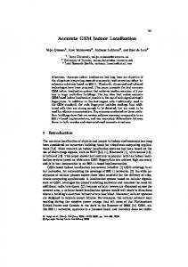
IV. RESULTS Mobile manipulators can operate in a wide range of environments, mainly indoors, and most of the time they are cluttered with unknown objects. Moreover, they move at different speeds depending on their task, safety restrictions and locomotion system. As such, to have a representative evaluation of the proposed localization system, several testing environments were devised for two different robot platforms. A. Testing platforms The localization system was tested on laser sensor data retrieved from two different robots and executed on the same computer in order to allow a direct comparison of computation time. This computer was a Clevo P370EM3 laptop with a Intel Core i7 3630QM CPU at 2.4GHz, 16 GB of RAM DDR3, NVidia GTX680M graphics card and a Samsung 840 Pro SSD. The sensor data was recorded into rosbags, and is publicly available at [16] along with all the detailed results and experiments videos, in order to allow future comparisons with other localization systems. The hardware specifications of the lasers used is presented in Table I and the laser points after downsampling and registration can be seen from Fig. 3 to Fig. 8 as green circles (inliers) and red circles (outliers). 1) Jarvis platform The Jarvis platform is an autonomous ground vehicle equipped with a SICK NAV350 laser for self-localization (mounted about 2 meters from the floor) and a SICK S3000 laser for collision avoidance (mounted about 0.20 meters from the floor). It uses a tricycle locomotion system with two back wheels and a steerable wheel at the front. In Fig. 1 the robot is performing a delivery task with the package on top of a moving support. The 3 DoF ground truth is provided by the SICK NAV350 system, uses 6 laser reflectors with 9 cm of diameter (shown as blue circles in Fig. 3 and 4) and is certified for robot docking operations with precision up to 4 millimeters. 2) Guardian platform The Guardian platform is an autonomous mobile manipulator equipped with a Hokuyo URG-04LX laser in the front and a Hokuyo URG-04LX_UG01 laser in the back (both mounted about 0.37 meters from the ground). The front laser had a tilting platform which allows 3D mapping of the environment. The arm is a SCHUNK Powerball LWA 4P and in Fig.2 it is attached to a stud welding machine. It uses a differential drive locomotion system and can be moved with wheels or with tracks. This platform didn’t have a certified ground truth and as such, the results of the performed tests could not be quantified with an external localization system (the results performed in the Gazebo simulator will be presented instead).
only reliable at low paces. As such, only the results of the robot moving at 5 cm/s will be show (along with the tests performed in the Stage simulator). These tests were performed with two different movement paths. The first is a simple rounded path that aimed to test the robot in the region of space that had better ground truth (due to its position in relation to the laser reflectors). The second path was more complex and contained several sub paths with different velocities and shapes (shown in Fig. 4 and 6). 2) Guardian in structured environment The structured environment simulated in Gazebo is a large room with 12.4 meters of length and 8.4 meters of depth. It has 4 doors, several small windows and the walls have small ledges at regular intervals (as can be seen in Fig. 7 and 8). Given that the Guardian mobile manipulator is expected to work on the walls of this environment, several tests were devised with a path following the lower and right wall of the environment (shown in Fig. 7). The first test was done in a static environment clear of unknown objects and was meant to evaluate the best precision that the localization system could achieve. The second test was done in a cluttered environment and was designed to test the robustness of the localization system against static unknown objects. The last test added a moving car to the scene and aimed to assess the impact of dynamic objects on the point cloud registration algorithms. C. Localization system results The main results of the tests performed with the localization system are presented in Table II. It summarizes each test by fitting a normal distribution for each evaluation metric. They were retrieved with a known initial pose using the ICP point-topoint as tracking algorithm and ICP point-to-plane as tracking recovery method. The Jarvis tests had a map built with the localization system in SLAM mode and were manually corrected to achieve a resolution of 10 mm. The Guardian tests rely on a map built from the CAD model and had a resolution of 2 mm. A voxel grid of 75 mm was applied to the assembled lasers scans in the Jarvis experiments while in the Guardian tests it was used a voxel grid of 25 mm. The initial pose estimation subsystem used SIFT for keypoint selection, FPFH for keypoint description and the feature matching algorithm of section III.7b to estimate the initial position and orientation of the robot. Figures 3 to 7 show the synchronized poses from the localization system (blue arrows), ground truth (green arrows) and odometry (red arrows) while Fig. 8 shows the accepted initial poses when the robot was in the lower right corner of the Guardian test environment. A regular grid with one meter spacing was applied on top of the figures to ease their analysis.
B. Testing environments The localization system was tested in different variations of two main environments. 1) Jarvis in RoboCup field The RoboCup field (shown from Fig. 3 to Fig. 6) is a large room with 20.5 meters of length and 7.7 meters of depth. It has two doors, several small windows and two large glass openings into the hallway. Several tests were performed with the robot at different speeds in this environment but the ground truth was
Fig. 1. Jarvis platform
Fig. 2. Guardian platform
TABLE I.
LASER HARDWARE SPECIFICATIONS
Laser model
Range (meters)
Field of view (degrees)
Scanning frequency (Hz)
Angular resolution (degrees)
SICK NAV350
[0.5..250]
360
8
0.25
15
SICK S3000
[0.1..49]
190
8
0.25
150
Hokuyo URG-04LX
[0.06..4.095]
240
10
0.36
10
Hokuyo URG-04LX_UG01
[0.02..4]
240
10
0.36
30
TABLE II.
3 DOF LOCALIZATION SYSTEM RESULTS Translation error (millimeters) Standard Mean deviation 5.608 3.280 6.235 3.242 2.817 1.551 4.479 3.769 4.710 2.788 2.476 1.370
Rotation error (degrees) Standard Mean deviation 0.634 0.169 0.529 0.157 0.038 0.026 0.106 0.137 0.135 0.134 0.017 0.017
Outliers percentage [0..100] Standard Mean deviation 12.21 4.50 20.16 5.87 16.11 0.93 15.82 1.14 16.13 0.92 17.00 0.92
Global computation time (milliseconds) Standard Mean deviation 7.065 6.456 7.827 7.990 12.600 12.459 24.500 13.592 16.432 12.291 10.374 12.138
2/1
3.557
1.800
0.033
0.040
17.61
1.33
14.863
15.898
2/1
4.199
2.596
0.048
0.110
17.84
1.23
13.150
14.351
2/2 2/2 2/2 2/2 2/2 2/2
2.642 4.961 2.912 6.713 4.593 5.847
0.463 3.953 0.856 6.380 3.802 5.585
0.016 0.032 0.020 0.141 0.069 0.105
0.023 0.084 0.026 0.203 0.072 0.125
0.0 0.0 25.05 30.39 33.33 34.20
0.0 0.0 13.30 14.66 9.88 16.64
5.723 6.365 11.889 25.367 22.217 26.892
1.868 2.906 9.084 35.724 32.408 35.630
Test conditions Platform
Ambient
Jarvis robot
Cluttered Cluttered dynamic
Path shape Rounded Complex Rounded
Jarvis simulator (Stage)
Cluttered Complex
Static Guardian simulator (Gazebo)
Cluttered Cluttered dynamic
Fig. 3.
Wall follower
Path velocities 5 cm/s 5 cm/s 5 cm/s 50 cm/s 100 cm/s 5 cm/s 50-30-5020 cm/s 200-30200-30 cm/s 5 cm/s 30 cm/s 5 cm/s 30 cm/s 5 cm/s 30 cm/s
Statistical error (millimeters)
Nº scans / Nº lasers 1/1 2/1 2/1 2/1 1/1 2/1
Rounded path using Jarvis robot at 5 cm/s
Fig. 4. Complex path using Jarvis robot at 5 cm/s
Fig. 5. Rounded path using Jarvis simulator at 50 cm/s
Fig. 6. Complex path using Jarvis simulator at 200-30-200-30 cm/s
Fig. 7. Wall path using Guardian at 30 cm/s in dynamic environment
Fig. 8. Initial pose estimation using feature matching
VI. CONCLUSIONS
V. RESULTS DISCUSSION The results achieved with the proposed localization system showed sub centimeter pose tracking and reliable initial pose estimation. As expected, the simulator tests at lower velocities had less mean error than the ones at higher speeds while requiring slightly less computation time. Also, the tests on the Jarvis robot had more mean error than the corresponding simulator tests. This is due to laser scan deformation that couldn’t be simulated and also because the simulators were only able to add Gaussian noise to the laser measurements. To compensate these limitations of the simulators, the error in odometry and laser measurements in simulation was deliberately higher than the expected values for the physical platforms. This explains why the localization system needed more time to perform the pose estimations in the simulator tests. It can also be seen that adding unknown objects increased the mean error and required computation time while adding dynamic objects increased these values even further (given that a moving object appears in a laser scan as a deformed version of its static shape). The ability to switch registration algorithms at runtime based on the quality of the estimated pose proved to be an efficient and flexible architecture choice, since it allowed high precision pose tracking with fast registration algorithms and occasional pose tracking recovery with more robust methods. The initial pose estimation using feature matching was very reliable and successfully found the robot location even in low feature surroundings (as can be seen in Fig. 8). Moreover, the output of the accepted initial pose estimations allows the detection of similar map locations by a navigation supervisor, which then can plot a path to disambiguate the initial pose and avoid dangerous operations at a wrong position. The statistical error of the lasers was mitigated by merging several laser scans before performing a point cloud registration. This is based on the fact that a considerable amount of laser noise follows a Gaussian distribution, and as such, the measurement errors can be significantly reduced by retrieving the centroids of a voxel grid applied over the laser data. However, assembling too much laser scans can lead to worse pose tracking if the robot is moving at high speeds, because the lasers would be projected into the map frame with a high position error (because odometry accuracy decreases when the robot speed increases and the localization system will not correct it). As such, the laser assembler allows dynamic reconfiguration of the number of laser scans to assemble (or the period of assembly time). This is a feature that besides improving the pose tracking, it also allows a supervisor to regulate the rate at which the localization system operates. This can be very useful for mobile manipulators because the localization system can have a high update rate when the robot is moving fast and a low update rate when it is moving slower or when it is stopped. This allows a more efficient usage of the platform hardware resources while also improving the localization system accuracy. The dynamic map update capability helped lowering the point cloud registration time while also increasing the accuracy by a small margin. Moreover, it improved the robustness of the initial pose estimations and allows better path planning for a navigation system.
The proposed localization system is able to maintain pose tracking with less than one cm in translation error at several velocities even in cluttered and dynamic environments. Moreover, when tracking is lost or no initial pose is given, the system is able to find a valid global pose estimate by switching to more robust registration algorithms that use feature matching. This approach achieved fast pose tracking and reliable initial pose estimation while also providing the distribution of the accepted initial poses before registration refinement, which can be very valuable information for a navigation supervisor when the robot is in an ambiguous region that can be registered in similar zones in the known map. The system also allows dynamic reconfiguration of the number of laser scans to assemble in order to mitigate laser measurement errors and adapt its rate of operation according to the robot current task and velocity. The sub centimeter accuracy achieved by the proposed localization system along with the dynamic map update capability and the need of no artificial landmarks will allow the fast deployment of mobile manipulators capable to operate safely and accurately in cluttered environments. ACKNOWLEDGMENT The authors would like to thank everyone involved in the CARLoS Project. This project has received funding from the European Commission Seventh Framework Programme for Research and Technological Development under the grant agreement number 606363, and from the national project "NORTE-07-0124-FEDER-000060". REFERENCES [1] [2] [3] [4] [5] [6] [7] [8] [9] [10] [11] [12] [13] [14] [15] [16]
E. a. Wan and R. Van Der Merwe, “The unscented Kalman filter for nonlinear estimation,” Proc. IEEE 2000 Adapt. Syst. Signal Process. Commun. Control Symp. (Cat. No.00EX373), vol. 7, pp. 153–158, 2000. R. Mautz, “Indoor positioning technologies,” ETH Zurich, 2012. K. Lingemann and A. Nüchter, “High-speed laser localization for mobile robots,” Robot. Auton. …, vol. 51, pp. 275–296, 2005. F. Pomerleau, “Methodology and Tools for ICP-like Algorithms,” ETH Zürich, 2013. A. Diosi, “Laser range finder and advanced sonar based simultaneous localization and mapping for mobile robots,” Slovak University of Technology in Bratislava, 2005. M. Magnusson, “The Three-Dimensional Normal-Distributions Transform — an Efficient Representation for Registration, Surface Analysis, and Loop Detection,” Örebro University, 2009. B. Kitt, A. Geiger, and H. Lategahn, “Visual odometry based on stereo image sequences with RANSAC-based outlier rejection scheme,” 2010 IEEE Intell. Veh. Symp., pp. 486–492, Jun. 2010. T. Whelan and H. Johannsson, “Robust real-time visual odometry for dense RGB-D mapping,” … (ICRA), 2013 IEEE …, 2013. S. Thrun, Probabilistic robotics, vol. 45. 2002. C. Costa, “Dynamic robot localization system.” [Online]. Available: https://github.com/carlosmccosta/dynamic_robot_localization. M. Quigley, K. Conley, B. Gerkey, J. FAust, T. Foote, J. Leibs, E. Berger, R. Wheeler, and A. Mg, “ROS: an open-source Robot Operating System,” Icra, vol. 3, p. 5, 2009. R. B. Rusu and S. Cousins, “3D is here: Point Cloud Library (PCL),” Proc. IEEE Int. Conf. Robot. Autom., pp. 1–4, May 2011. P. J. Besl and N. D. McKay, “A method for registration of 3-D shapes,” IEEE Trans. Pattern Anal. Mach. Intell., vol. 14, no. 2, pp. 239–256, 1992. R. B. Rusu, N. Blodow, and M. Beetz, “Fast Point Feature Histograms (FPFH) for 3D registration,” 2009 IEEE Int. Conf. Robot. Autom., pp. 3212–3217, May 2009. A. Hornung, K. M. Wurm, M. Bennewitz, C. Stachniss, and W. Burgard, “OctoMap: An efficient probabilistic 3D mapping framework based on octrees,” Auton. Robots, vol. 34, no. 3, pp. 189–206, Feb. 2013. C. Costa, “dynamic_robot_localization_tests.” [Online]. Available: https://github.com/carlosmccosta/dynamic_robot_localization_tests.