Index Termsâ Cross-layer design, wireless profiled TCP, ver- tical handover, integrated wireless networks. I. INTRODUCTION. HE increasing demand of supporting diverse multimedia services from .... We also consider the SACK extensions.
This article has been accepted for publication in a future issue of this journal, but has not been fully edited. Content may change prior to final publication.
VT-2006-00767
1
Robust Cross-layer Design of Wireless Profiled TCP Mobile Receiver for Vertical Handover Humphrey Rutagemwa, Student Member, IEEE, Sangheon Pack, Member, IEEE Xuemin (Sherman) Shen, Senior Member, IEEE, and Jon W. Mark, Life Fellow, IEEE
Abstract—In this paper, we consider downward and upward vertical handovers in integrated wireless LAN and cellular networks, and address Wireless Profiled TCP (WP-TCP) premature timeouts due to step increase of round-trip time and false fast retransmit due to packet reordering. Specifically, we develop a mobile receiver centric loosely coupled cross-layer design, which is easy to implement and deploy, backward compatible with the Wireless Application Protocol version 2 (WAP 2.0) architecture, and robust in the absence of perfect cross-layer information. We propose two proactive schemes called RTT Inflation and RTT Equalization. The RTT Inflation scheme suppresses premature timeouts by carefully inflating retransmission timeout time and the RTT Equalization scheme prevents false fast retransmit by equalizing the round-trip delay experienced by all packets. We conduct extensive simulations to evaluate the performance in downward and upward vertical handovers. It is demonstrated that the proposed schemes significantly improve the performance in a wide range of network conditions. Index Terms— Cross-layer design, wireless profiled TCP, vertical handover, integrated wireless networks.
ken before the new connection is made and soft vertical handover is when the new connection is made before the old connection is broken. Unless explicitly stated otherwise, throughout this paper, the term vertical handover refers to soft vertical handover. Internet
Correspondent node Cellular network
WLAN hotspot 1 WLAN hotspot 2
Mobile node
Fig. 1. An integrated WLAN and cellular network architecture.
T
I.
INTRODUCTION
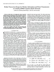
HE increasing demand of supporting diverse multimedia services from mobile users has led to the integration of a variety of wireless networks such as cellular networks (e.g., GPRS/UMTS) and wireless LANs (e.g., 802.11x and HiperLAN/2) [1]. Fig. 1 shows an architecture for heterogeneous wireless network where wireless LAN (WLAN) and cellular networks are integrated. The integration can be in a tightlycoupled or loosely-coupled manner [2]. In the tightly-coupled integration, WLANs are directly connected to the cellular network which is connected to the Internet (WLAN hotspot 2 and the cellular network). In this case, the WLAN access appears to the cellular network as any other cellular access network. In the loosely-coupled integration, WLANs are directly connected to the Internet (WLAN hotspot 1 and the cellular network). In integrated WLAN and cellular networks a mobile node can switch between WLANs and cellular networks. An event where a mobile node switches from one network to a different type of network is called vertical handover. The vertical handover from WLANs to the cellular network is referred to as upward vertical handover and the vertical handover from the cellular network to WLANs is referred to as downward vertical handover. The vertical handover can also be hard or soft. Hard vertical handover is when the old connection is bro-
The integration of WLAN and cellular networks poses several challenges such as sudden network characteristics change, handover, etc. Therefore, a stable and efficient transport mechanism is required. Wireless Application Protocol version 2 (WAP 2.0) [3] is one of the promising transport mechanisms for integrated WLANs and cellular networks. It uses Wireless Profiled TCP (WP-TCP) [4], which is fully compatible with TCP, as one of the reliable transport protocols to cope with the wireless network characteristics. WP-TCP utilizes a windowbased congestion control mechanism [5],[6]. The WP-TCP sender maintains a congestion window, which limits the number of outstanding unacknowledged data segments in the network, and a slow-start threshold, which determines the rate of adjusting the congestion window. Whenever a new acknowledgement (ACK) is received, the congestion window is increased by one segment if it is below the slow-start threshold (slow-start phase) or by 1/(congestion window) if it is equal to or greater than the slow-start threshold (congestion avoidance phase). In either phase, the upper limit of congestion window increase is the maximum window size. The WP-TCP sender assumes a packet is lost either after a timeout or after receiving a certain number of consecutive duplicate ACKs (ACK with the same sequence number as the previous ACK). This number is normally referred to as the duplicate ACK thresh-
This article has been accepted for publication in a future issue of this journal, but has not been fully edited. Content may change prior to final publication.
VT-2006-00767 old. When a timeout occurs, the slow-start threshold is set to max{2, (congestion window)/2} and the congestion window is reset to one. The lowest unacknowledged packet is retransmitted and the WP-TCP sender enters the slow-start phase. In the case of packet loss, indicated by duplicate ACKs, fast retransmit is invoked followed by fast recovery. The fast recovery procedure ensures that the congestion avoidance phase follows after fast retransmit and not the slow-start phase. When WP-TCP is deployed in an integrated WLAN and cellular network, its performance can dramatically degrade during or shortly after vertical handover. This can be due to bandwidth-delay product mismatch, premature timeouts, inrush packet transmission, false fast retransmit, and burst packet losses. During hard upward or downward vertical handover, all or a large number of in-flight data and acknowledgement packets can get lost. This can result in burst losses of data packets which can only be recovered by costly timeout mechanism. Furthermore, the burst losses of acknowledgment packets can lead to unnecessary stalling of the transmission process. WP-TCP uses a congestion window to control the number of in-flight packets which is ideally equivalent to the bandwidth-delay product of the network path. The congestion window is limited to the TCP maximum window and adjusted according to the AIMD congestion control mechanism [7]. Since the congestion window is usually adjusted slowly, any abrupt change in bandwidth-delay product after vertical handover can result in congestion of the bottleneck link or underutilization of the new network path. During soft upward vertical handover, the WP-TCP sender continues to transmit data packets through cellular network at the same (or higher) rate of receiving acknowledgement packets from the WLAN. Since the WLAN has relatively higher bandwidth as compared to the cellular network, the inrush data packets transmission in cellular network can lead to temporary congestion and packet losses which in turn degrade the WP-TCP performance. After soft upward vertical handover the round-trip time delay can suddenly and significantly increase resulting in WP-TCP premature timeouts. The premature timeouts can degrade the WPTCP performance by triggering unnecessary packet retransmission and congestion control response. When soft downward vertical handover occurs, new data packets transmitted through WLAN can arrive at the WP-TCP receiver before the old data packets transmitted through the cellular network (i.e., data packet reordering). The data packet reordering can generate a sufficiently large number of duplicate acknowledgement packets which may result in false fast retransmit. The false fast retransmit can degrade WP-TCP performance by triggering unnecessary packet retransmission and congestion control response. In the literature, there are several schemes proposed to reduce the effects of burst packet losses due to network disconnections during hard vertical handover [8],[9], network congestion or underutilizations due to bandwidth-delay product mismatch [10]-[12] and inrush packet transmission [12], and premature timeouts and false fast retransmit due to temporary [13]-[15] or permanent [16],[17] increase of round-trip time. The schemes proposed in [13]-[15] detect falsely triggered
2 fast retransmit or timeouts, and then undo invoked congestion control actions. These schemes are reactive by nature and they are suitable for homogeneous wireless networks. Recently, various proactive schemes that consider heterogeneous wireless networks have been proposed to specifically enhance the performance of TCP in soft vertical handover. In [16], three network layer schemes (fast response, slow response, and ACK delay) are developed to decrease the chance of premature timeouts in soft upward vertical handover. This is achieved by breaking a one-step increase of round-trip time into a two-step increase during handover. The developed schemes work well if the difference between round-trip times before and after the handover is small. As the difference between round-trip times increases these schemes become ineffective. Nodupack TCP scheme has been proposed in [17] to improve the behavior of TCP during soft downward vertical handover by suppressing false fast retransmit. In this scheme, the TCP receiver needs to have knowledge of TCP sender duplicate acknowledgement threshold parameter. Unfortunately, the implementation of this mechanism is not given and may need to be defined in the TCP option. It is evident that the WP-TCP performance degradation during vertical handover is primarily due to the misinterpretation of the apparent information such as packet losses, packet reordering, round-trip time increase. We argue that an effective approach to completely address the performance degradation problem is to make information from some layers available to other layers and allow the coordinated smart decisions to take place at each layer. This argument necessitates the use of a cross-layer coupling [25] approach in improving the performance during vertical handover. However, a cross-layer coupling may lead to unintended interactions that may cause system instability and inflexibility [26]. Therefore, it is important to carefully design and minimize the degree of dependence and exchanged information between non-adjacent layers. In this paper, we consider integrated WLAN and cellular networks, and address two WP-TCP performance barriers in vertical handover: premature timeout due to step increase of round-trip time and false fast retransmit due to packet reordering. Firstly, we develop a mobile receiver centric loosely coupled cross-layer design, which is easy to implement and deploy, backward compatible with the WAP 2.0 architecture, and robust in the absence of cross-layer information. Secondly, based on the developed design, we propose two proactive schemes which prevent false fast retransmit by equalizing the round-trip delay experienced by all packets and suppress premature timeouts by carefully inflating retransmission timeout time. Finally, we conduct extensive simulations and analyze the performance of the proposed schemes in downward and upward vertical handovers. It is demonstrated that our schemes outperform other schemes and significantly improve the performance in a wide range of network conditions. The rest of this paper is organized as follows: Section II describes the system model. Section III presents the developed cross-layer design and the proposed proactive schemes for vertical handover. Section IV analyzes the proposed proactive schemes in ideal network environment. Simulation results are
This article has been accepted for publication in a future issue of this journal, but has not been fully edited. Content may change prior to final publication.
VT-2006-00767
3
II. SYSTEM DESCRIPTION We consider heterogeneous wireless networks where WLANs and cellular networks are integrated as illustrated in Fig. 1. A mobile node is equipped with WLAN and cellular network interfaces, and it can use them simultaneously. Since cellular network has very large coverage area compared to the WLAN hotspots, it is reasonable to assume that cellular network is overlaid on disjoint WLAN hotspots. Therefore, cellular network is always accessible and WLANs are only accessible in distinct hotspots. At the network layer, Mobile IPv6 [18] provides mobility support between the WLAN and the cellular network, and the Internet Control Message Protocol (ICMPv6) [19] echo/reply messaging enables the estimation of round-trip time. At the transport layer, WP-TCP is used to provide an endto-end reliable service. We consider WP-TCP to be implemented with all mandatory requirements (RFC 0793, RFC 1122 [20], RFC 2581 [5], and Selective Acknowledgement (SACK) describe in RFC 2018 [21]) and at least one optional requirement (Timestamps option (RFC 1323) for round-trip time measurement). We also consider the SACK extensions described in RFC 3517 [22] for loss recovery mechanism and RFC 2988 [23] for computing retransmission time. The standard procedure for measuring round-trip time using timestamps option and computing retransmission time are summarized as follows. Whenever a data packet is sent, the WP-TCP sender places a timestamp in the Timestamp Value field (TSVal) in the data packet. The timestamp value is obtained from a local clock. When a new in-order data packet is received at the WP-TCP receiver, the timestamp value from TSVal is stored in a local variable TS.recent. Whenever an acknowledgement packet is sent, the WP-TCP receiver copies the current timestamp stored in TS.recent to the Timestamp Echo Reply field (TSecr) in the acknowledgement packet. When a valid acknowledgement packet arrives at the WP-TCP sender, the sample round-trip time (RTT) is computed as a difference between the current time of the local clock and the timestamp echoed in the TSecr. For every RTT sampled at the WP-TCP sender, retransmission time (RTO) is computed by using the following procedural steps. RTTVAR ← (1 − β ) ⋅ RTTVAR + β ⋅ SRTT − RTT (1) and SRTT ← (1 − α ) ⋅ SRTT + α ⋅ RTT , (2) where SRTT (smoothed round-trip time) and RTTVAR (roundtrip time variation) are state variables, and α = 1/8 and β = 1/4. The WP-TCP sender updates the RTO as RTO ← SRTT + max {G, k ⋅ RTTVAR} , (3)
where G is a clock granularity and k = 4. III. CROSS-LAYER DESIGN Our previous work in [24] suggests that the performance of
WP-TCP in integrated WLAN and cellular networks could be improved by jointly considering some parameters of data link, network, and transport layers. In this study, we propose a cross-layer design to improve the performance. From cautionary perspective presented in [26], a poor cross-layer design can lead to unintended interactions that may cause system instabilities and performance degradation. Furthermore, a tightly coupled cross-layer design can lead to inflexibility that may potentially hinder future innovations. To avoid these potential problems, we consider a loosely coupled design where all non-adjacent layers can only interact indirectly through the enhancement module. Since, at the mobile node, it is easy to collect the information about the vertical handover and the status of the wireless channels, we further consider a mobile receiver centric design to simplify the implementation. In the next subsections we present the protocol architecture of the proposed mobile receiver centric loosely coupled cross-layer design and develop schemes for vertical handover. A. Protocol Architecture of Cross-layer Design Figure 2 shows the protocol architecture of the proposed cross-layer design. The architecture has two main components: communication protocol stack and enhancement module. The layers involved in the communication protocol stack include the transport layer (Wireless Profiled TCP), the network layer (Mobile IP and ICMP), and the data link layer (cellular network and WLAN). Direct inter-layer communication is restricted to adjacent layers (vertical arrows). The enhancement module handles critical protocol configurations and executes schemes to enhance the overall performance. It can query or change state variables of the communication protocols (horizontal arrows).
Wireless Profiled TCP (Transport layer) Enhancement Module
presented in Section V, followed by concluding remarks in Section VI.
ICMP
Mobile IP
(Network layer)
WLAN
Cellular network (Data link layer)
Fig. 2. Protocol architecture for proposed cross-layer design. B. Schemes for Vertical Handover In this subsection, we develop two schemes which are used by the enhancement module to improve the performance in upward and downward vertical handovers. We name the developed schemes for upward and downward vertical handovers RTT Inflation and RTT Equalization, respectively. 1) RTT Inflation Scheme We address the problem of premature timeout in upward
This article has been accepted for publication in a future issue of this journal, but has not been fully edited. Content may change prior to final publication.
VT-2006-00767 vertical handover by carefully inflating the round-trip time samples measured at the WP-TCP sender. We achieve this by modifying the standard procedure for round-trip time measurement at the WP-TCP receiver (described in Section II). The proposed procedure at the WP-TCP receiver is shown in Fig. 3. We introduce two new variables, TS .correction and TO.initial, at the WP-TCP receiver. The variable TS .correction tracks elapsed time after a new in-order data packet is received. The amount of elapsed time is used to correct the round-trip time samples measured at the WP-TCP sender from being overestimated. The variable TO.initial stores the amount of time needed to be inflated in the roundtrip time. On the conservative side, the inflated time is kept slightly higher than the estimated round-trip time in the cellular network. The estimated round-trip time in the cellular network can be computed as icmp.RTT + MSS/bBS , where icmp.RTT is the round-trip time found by using ICMP messaging, MSS is maximum segment size (data packet length), and bBS is data transmission rate of the base station (BS) in the cellular network. If the ICMP messaging method fails to estimate the round-trip time before the upward vertical handover is triggered, TO.initial is set to the value of the WP-TCP sender initial retransmission timeout. This value is usually between 2.5 to 3 seconds. The proposed RTT Inflation scheme at the WP-TCP receiver for upward vertical handover is summarized as follows. If hard upward vertical handover is expected (predicted by using link status), the standard procedure at the WP-TCP receiver is followed and all generated acknowledgment packets are transmitted through the cellular network interface. Otherwise, if hard upward vertical handover is not expected the following procedure is used: a) Just before initializing the handover, estimate the round-trip time in the cellular network (Fig. 3, STEP #1). After initializing the handover, generate a duplicate acknowledgement packet with inflated round-trip time (Fig. 3, STEP #3) and transmit it through the WLAN interface. Also, generate a duplicate acknowledgement packet (Fig. 3, STEP #4) and transmit it through the cellular network interface. b) When a new out-of-order data packet is received from the WLAN interface, generate the corresponding duplicate acknowledgement packet with inflated round-trip time (Fig. 3, STEP #3) and transmit it through the WLAN interface. c) When a new in-order data packet is received from the WLAN interface, update the timer variables (Fig. 3, STEP #2). Generate a corresponding acknowledgement packet with inflated round-trip time (Fig. 3, STEP #3) and transmit it through the WLAN interface. d) When a new out-of-order data packet is received from the cellular interface, generate a corresponding duplicate acknowledgement packet (Fig. 3, STEP #4) and transmit it through the cellular network interface. e) If a new in-order data packet is received from the cellular network interface, it implies that the vertical handover is completed. Generate a duplicate acknowledgement packet with half of inflated round-trip time (Fig. 3, STEP #3) and
4
transmit it through the WLAN interface. Furthermore, generate a duplicate acknowledgement packet (Fig. 3, STEP #4) and transmit it through the cellular network interface. Deactivate the RTT Inflation scheme and follow the standard procedure at the WP-TCP receiver. STEP #1 If icmp rtt estimation is successful { TO.initial = icmp.RTT + Ldata /RBS } else { TO.initial = default (3sec) } STEP #2 If receive new in-order data packet { TS .recent = data.TSval TS .correction = 0 } STEP #3 If send acknoledgment packet with inflated round -trip time { ack .TSecr = TS .recent + TS .correction − TO.initial } STEP #4 If send acknoledgment packet with real round - trip time{ ack .TSecr = TS .recent } Fig. 3. Modified RTT measurement procedure at the WP-TCP receiver.
2) RTT Equalization Scheme We prevent false fast retransmit due to packet reordering during downward vertical handover by equalizing the roundtrip delay experienced by all packets. The round-trip delay constitutes the packet transmission delay and propagation delay along the network path. We equalize the propagation delays of all packets by sending the acknowledgement packets correspond to data packets received from the cellular network and WLAN through the WLAN and cellular network, respectively. We equalize the transmission delays for all packets by delaying the acknowledgement packets sent through the cellular network with approximately cellular network data packet transmission time T. If the cellular network data transmission rate is not available on time, the equalization of transmission delays can be ignored. Therefore T can be computed as ⎧ MSS / bBS , if bBS is available (4) T =⎨ ⎩0, otherwise, where MSS is maximum segment size (data packet length) and bBS is data transmission rate of the base station (BS) in the cellular network. The proposed RTT Equalization scheme at the WP-TCP receiver for downward vertical handover is summarized as follows: a) When a new out-of-order data packet is received from the cellular network interface, transmit the duplicate acknowledgement packet through the WLAN interface. b) When a new out-of-order data packet is received from the WLAN interface, wait for the time T computed in (4) and transmit the duplicate acknowledgment packet through the cellular network interface. c) When a new in-order data packet is received from the cellular network interface, transmit the corresponding ac-
This article has been accepted for publication in a future issue of this journal, but has not been fully edited. Content may change prior to final publication.
VT-2006-00767
5
knowledgement packets through the WLAN interface. And then cancel the transmission of all delayed (outstanding) duplicate acknowledgment packets with lower acknowledgement numbers in step (b). d) If a new in-order data packet is received from the WLAN interface, it implies the vertical handover is completed. Transmit the corresponding acknowledgement packet through the WLAN interface. Deactivate the RTT Equalization scheme and follow the standard procedure at the WP-TCP receiver. IV.
PERFORAMANCE ANALYSIS
In this section, we analyze the proposed schemes for vertical handover in an ideal network environment where a single pair WP-TCP sender-receiver runs over integrated WLAN and cellular networks without packet losses. Consider WP-TCP sender duplicate acknowledgement threshold (Z) and congestion window (w) measured in packets, size of data packet (MSS) and acknowledgement packet (MAS) measured in bits, one-way channel delay of cellular network (lBS ) and WLAN (l AP ) measured in seconds, bandwidth in cellular network (bBS ) and WLAN (bAP ) measured in bits per second, and bandwidth-delay product (BDP) of the network in use before the vertical handover measured in packets and computed as BDP = 2li bi / MSS + 1, (5) for all i ∈ {BS, AP}. A. Upward Vertical Handover Consider the RTT Inflation scheme proposed to suppress premature timeouts due to upward vertical handover in the ′ and tnow respectively denote the Subsection III.B.1. Let tnow timestamp time set by the WP-TCP sender in TSVal of the last data packet received before step (a) is executed and the time when the duplicate acknowledgement packet sent through WLANs in step (a) is received at the WP-TCP sender. From Section II, the sample round-trip time (RTT) at the WP-TCP sender is computed as RTT = tnow − TSecr. (6) By definition, tnow can be written as ′ + RTTWLAN + TS .correction, tnow = tnow
(7)
where RTTWLAN is the round-trip time in the WLAN. From step (a) and Fig.3 STEP #3, TSecr is computed as ′ + TS .correction − TO.initial. TSecr = tnow (8) From RTT measurement procedure at the WP-TCP sender (Section II) and the WP-TCP receiver (Fig. 3, STEP #2), ′ data.TSval = tnow and TS .recent = data.TSval , respectively. Therefore, from (6), (7), and (8), the first sample RTT measured after vertical handover can be found as RTT = RTTWLAN + TO.initial. (9) Assuming just before upward vertical handover WLAN is in a steady state, the smoothed round-trip time and round-trip time variation are given as SRTT = RTTWLAN and RTTVAR = 0, respectively. Let RTOi be the retransmission timeout com-
puted after the i th received inflated sample RTT. From (1)-(3) , the retransmission timeout computed after the first inflated sample RTT, which is obtained from the duplicate acknowledgement packet (see step (a) ), can be found as RTO1 = RTTWLAN + 1.1250 ⋅ TO.initial. (10) Similarly, the retransmission timeout computed after the second inflated sample RTT, which is obtained from the new acknowledgement packet (see step (c)), can be found as RTO2 = RTTWLAN + 1.8594 ⋅ TO.initial. (11) All subsequent retransmission timeouts, which are computed from inflated sample RTTs, are at least equal to inflated sample RTTs. Therefore, RTO ≥ RTTWLAN + TO.initial , (12) Since the TO.initial is kept slightly higher than the estimated round-trip time in the cellular network ( RTTWWAN ) for the RTT Inflation scheme, (12) can be rewritten as RTO ≥ RTTWLAN + RTTWWAN , (13) From (13) and the discussion presented in [24, Subsection III.D.2], it is evident that the premature timeouts can not occur when w is greater than half of BDP. When w is equal to or less than half of BDP, premature timeouts can rarely occur and only in a very extreme network setup. B. Downward Vertical Handover Consider the RTT Equalization scheme proposed to prevent false fast retransmit due to downward vertical handover in the Subsection III.B.2. To analyze the RTT Equalization scheme, we consider two cases: 1) when w is greater than BDP (i.e., w > 2lBS bBS / MSS + 1) and 2) when w is equal to or less than BDP (i.e., w ≤ 2lBS bBS / MSS + 1). Case I: When w > 2lBS bBS / MSS + 1 . In this case, the false fast retransmit due to downward vertical handover can occur if the following two conditions are satisfied. The first condition is that, a burst of more than Z data packets must be injected in the WLAN. But the burst of data packets can only be created if the first acknowledgement packet sent through the WLAN interface overtakes the in-flight acknowledgement packets sent through the cellular network interface before the downward vertical handover is initiated. Therefore, to satisfy this condition, the inequality lBS − ( MAS / bAP + l AP ) ≥ Z ⋅ MSS / bBS (14) must be valid. The second condition is that, at least Z duplicate acknowledgement packets transmitted in step (b) must arrive at the WP-TCP sender before the next new acknowledgement packet in step (c). Therefore, to satisfy this condition, the inequality MSS / bBS + (MAS / bAP + lAP ) ≥ Z ⋅ MSS / bAP + T + (MAS / bBS + lBS ) (15) must be valid. If the first and second conditions are satisfied, the inequality MSS / bBS ≥ Z ⋅ MSS / bBS + Z ⋅ MSS / bAP + T + MAS / bBS (16) obtained by adding (14) and (15) must also be valid. Note that Z ≥ 1 in (16) and the other variables are non-negative. Therefore, the inequality (16) is always not valid. This implies that the first and second conditions can not be simultaneously sat-
This article has been accepted for publication in a future issue of this journal, but has not been fully edited. Content may change prior to final publication.
VT-2006-00767 isfied and therefore the false fast retransmit can not occur. Case II: When w ≤ 2lBS bBS / MSS + 1 . In this case, the false fast retransmit due to downward vertical handover can occur either as described in Case I or when the following two conditions are satisfied. The first condition is that at least a block of Z data packets sent through the WLAN interface overtakes at least one in-flight data packet sent through the cellular network during downward vertical handover. To satisfy this condition, the inequality lBS + MSS / bBS ≥ l AP + Z ⋅ MSS / bBS (17) must be valid. Note that even though the transmission time of a data packet in the WLAN is MSS / bAP , the inter-departure time of data packets transmitted in the WLAN is equal to the inter-arrival time of acknowledgement packets in the cellular network at the WP-TCP sender, which is MSS / bBS (i.e., TCP ACK-clocking in the steady-state conditions). The second condition is that at least Z duplicate acknowledgement packets in step (b) arrive at the WP-TCP sender before the next new acknowledgement packet in step (c). Therefore, to satisfy this condition, the inequality ACK / bAP + l AP ≥ T + ( MAS / bBS + lBS ) (18) must be valid. If the first and second conditions are satisfied, the inequality MSS / bBS + MAS / bAP ≥ Z ⋅ MSS / bBS + T + MAS / bBS (19) obtained by adding (17) and (18) must also be valid. Note that bAP ≥ bBS , Z ≥ 1, and the other variables are non-negative. Therefore, the inequality (19) is always not valid. This implies that the first and second conditions can not be simultaneously satisfied, i.e., the false fast retransmit can not occur. From the two cases, it is clear that false fast retransmit can not occur in an ideal network environment even in the worst case configurations (i.e., Z = 1 and T = 0). Note that in the RTT Inflation scheme, T is recommended to be set to cellular network data packet transmission time (T = MSS / bBS ) in order to reduce the number of unnecessary transmitted duplicate acknowledgement packets and further avoid false fast retransmit in a real network environment. V.
SIMULATION RESULTS AND DISCUSSION
We evaluate the performance by using our network simulator testbed [27] and double check the results with the ns-2 simulator [28]. The simulation topology is shown in Fig. 4. AP, BS, and CR represent an access point in the WLAN, a base station in the cellular network, and a common router, respectively. A single, long-lived WP-TCP flow is configured to run over the integrated WLAN and cellular network, where the WP-TCP sender is the correspondent node (CN) and the WP-TCP receiver is the mobile node (MN). WP-TCP is simulated as described in Section II. The independent duplex wireline links BS-CR and AP-CR are set with large bandwidths and small delays whereas the common duplex wireline link CR-CN is set with large bandwidth and variable delay. A packet traversing this link experiences a delay which is uniformly distributed over the interval [l − 0.5Δl,l + 0.5Δl], where
6 l is the one-way link delay and Δl is the maximum delay deviation. The duplex wireless links MN-AP and MN-BS are set with small bandwidths, large link delays (lAP and lBS) and high packet loss rates (eAP and eBS). Each simulated data point is obtained as an average of 300 simulation runs repeated with different random seeds. If not stated otherwise, the simulation parameters are given as maximum delay deviation Δl = 0.04 sec, one-way wireline link delay l = 0.1 sec, cellular network one-way delay lBS = 1.0 sec, WLAN one-way delay lAP = 0.1 sec, cellular network packet loss rate eBS = 0.00, WLAN packet loss rate eAP = 0.00, WP-TCP maximum window size = 37 packets, WP-TCP duplicate ACK threshold = 3 packets, minimum retransmission timeout = 0.2 sec, WP-TCP data packet size (maximum segment size (MSS)) = 1KB, and WP-TCP acknowledgement packet size (maximum acknowledgement size (MAS)) = 0.05KB. Other parameters are given in Fig. 4. The metric of our interest in evaluating the performance of the proposed schemes is the number of in-order data packets received in 4 seconds after downward vertical handover is initiated and 40 seconds after upward vertical handover is initiated. To facilitate the analysis, we also monitor the occurrence of false fast retransmit in downward vertical handover and premature timeouts in upward vertical handover. In [24, Eqn. 15], it is indicated that after a single timeout the slowstart threshold is set to half of the current congestion window and the congestion window is set to one whereas after two or more consecutive timeouts slow-start threshold is set to two (the minimum value) and the congestion window is set to one. Consequently, we only monitor single premature timeouts and two consecutive premature timeouts. To appreciate the performance gained by the proposed schemes, we also present the performance of three schemes which are commonly used during vertical handover in multi-radio receivers. For simplicity, we refer to these schemes as Bicast, Same Interface, and New Interface. In the Bicast scheme, each acknowledgement packet is sent through both the WLAN interface and the cellular network interface. In the Same Interface scheme, each acknowledgement packet is sent through the network interface from which the corresponding data packet is received [12], and in the New Interface scheme, each acknowledgement packet is always sent through a new network interface [17]. BS TCP receiver
MN
(100Mbps,10ms) TCP sender
(144Kbps,lBS,eBS)
CR (1Mbps,lAP,eAP)
AP
(100Mbps,l ±Δl)
CN
(100Mbps,10ms)
Fig. 4. Simulation topology.
In the following subsections we analyze the impact of WPTCP protocol parameters, network conditions, and imperfect cross-layer information. In Figs. 5-12, it is interesting to note that Bicast and Same Interface schemes perform almost the
This article has been accepted for publication in a future issue of this journal, but has not been fully edited. Content may change prior to final publication.
VT-2006-00767
schemes respectively have lower percentage of premature timeouts and false fast retransmits as compared to other schemes. Since premature timeouts and false fast retransmits invoke WP-TCP congestion control that subsequently reduce the congestions window, the performance of the proposed schemes can be improved more than that of the other schemes as the congestion window increases. 800
Number of packets received
same in upward vertical handover whereas Bicast and New Interface schemes performance almost the same in downward vertical handover. In Bicast scheme, acknowledgment packet sent through cellular network is always ignored because it takes longer time to arrive at the WP-TCP than the duplicate copy sent through WLAN. Hence, in upward vertical handover the Bicast and Same Interface schemes have same effect to the WP-TCP sender most of times. Similarly, during downward vertical handover the Bicast and New Interface schemes have same effect to the WP-TCP sender most of times.
7
A. Effects of WP-TCP Parameters
2) WP-TCP congestion window In Subsection IV, it is indicated that the size of congestion window affects the vertical handover performance of the proposed schemes in an ideal network environment. In order to further understand the effects of congestion window on the proposed schemes in more realistic network environments, we monitor its size just before vertical handover is initialized and investigate the performance. The effects of congestion window in upward and downward vertical handover are respectively illustrated in Figs. 6 and 7. From Fig. 6.a and Fig. 7.a, the performance of all schemes is improved as congestion window increases but the improvement for RTT inflation and RTT Equalization schemes is much more than those in other schemes. It can be seen that for all schemes the percentage of premature timeouts (Fig. 6.b and 6.c) remain fairly unchanged while the percentage of false fast retransmit (Fig. 7.b) increases significantly as congestion window increases. However, the proposed RTT Inflation and RTT Equalization
(a)
600
500 RTT Equalization Bicast 400
Same Interface New Interface
300 2
3
4
5
6
7
8
9
10
9
10
Duplicate ACK threshold (packets)
100% 90% Percentage of false fast retransmit
1) WP-TCP duplicate ACK threshold To demonstrate the effectiveness of the RTT Equalization scheme, we observe the percentage of false fast retransmit and the number of in-order data packets received in a specified time interval for various values of WP-TCP duplicate ACK threshold. Fig. 5.a shows the number of in-order data packets received in 4 seconds. It can be seen that when duplicate ACK threshold is set to 4 packets, the number of in-order data packets received for the RTT Equalization scheme is nearly 45% more than those in the other schemes. This performance gain is due to the fact that the RTT Equalization scheme significantly prevents false fast retransmit, which is triggered because of packet reordering during downward vertical handover, by equalizing the round-trip delay experienced by all packets. This explanation is supported with the results in Fig. 5.b, where the percentage of false fast retransmit in 4 seconds is presented for various values of WP-TCP duplicate ACK threshold. It can be seen that in the RTT Equalization scheme the duplicate ACK threshold only needs to be set to 4 packets to completely prevent false fast retransmit whereas in other schemes the duplicate ACK threshold needs to be set to more than 10 packets. In other words, the RTT Equalization scheme has on average suppressed more than 6 unnecessary duplicate acknowledgements packets which would otherwise trigger the false fast retransmit.
700
80%
(b)
70% 60% 50% 40%
RTT Equalization 30%
Bicast
20%
Same Interface New Interface
10% 0% 2
3
4
5
6
7
8
Duplicate ACK threshold (packets)
Fig. 5. Impact of duplicate ACK threshold in Downward vertical handover.
B. Effects of Network Conditions 1) Impact of network delay The effects of the cellular network one-way delay in upward vertical handover and the WLAN one-way delay in downward vertical handover are respectively shown in Fig. 8 and Fig. 9. Due to an increase in round-trip time, the performance of all schemes in vertical handover degrades as the cellular network and WLAN one-way delays increase. In upward vertical handover the performance of the RTT Inflation scheme degrades much slower than other schemes (Fig. 8.a). In downward vertical handover the performance of the RTT Equalization scheme degrades much faster than other schemes (Fig. 9.a). These observations can be explained as follows. The cellular network one-way delay is always greater than or equal to the WLAN one-way delay. Therefore, the increase of the cellular network one-way delay or decrease of the WLAN oneway delay increases a step change of round-trip time which is experienced in vertical handover. The step change of roundtrip time significantly affect the percentage of premature time-
This article has been accepted for publication in a future issue of this journal, but has not been fully edited. Content may change prior to final publication.
VT-2006-00767
8
outs (Fig. 8.b and 8.c) and false fast retransmits (Fig. 9.b) of other schemes but not the RTT Inflation scheme and RTT Equalization scheme, respectively. Note that the premature timeouts and false fast retransmits observed from RTT Inflation and RTT Equalization respectively are mainly due to delay variation (Δl) set in the common duplex wireline link CRCN. 350 300 250 200
(a)
100
1000
RTT Inflation Bicast Same Interface New Interface
150
900
50 12
22
32
42
52
62
Congestion window (packets)
80%
700 600 500 400
RTT Equalization Bicast
300
Same Interface New Interface
100 10
20
RTT Inflation
60%
90%
Same Interface
(b)
New Interface
20%
12
22
32
40
50
60
100%
Bicast 40%
30
Congestion window (packets)
0% 42
52
62
Congestion window (packets) Percentage of consecutive premature timeout
(a)
800
200
Percentage of false fast retransmit
Percentage of single premature timeout
100%
Number of packets received
Number of packets received
400
causes dual effects as shown in Fig. 10.b and 10.c. If the percentage of premature timeout is already high, it slightly reduces the occurrence of premature timeouts by inflating retransmission timeout time. If the percentage of premature timeout is low, it slightly increases the occurrence of premature timeouts by inducing delay spikes. Since delay variation significantly affect the occurrence of false fast retransmit (Fig. 11.b), and hence a dominant factor, the performance of all schemes degrades as delay variation increases (Fig. 10.a). In downward vertical handover, the percentage of false fast retransmit is significantly affected by the delay variation (Fig. 11.b). Consequently, the performance in all schemes severely degrades as the delay variation increases (Fig. 11.a).
(b)
80%
RTT Equalization Bicast Same Interface New Interface
70% 60% 50% 40% 30% 20% 10% 0%
80%
10
70%
RTT Inflation
60%
Bicast
20
30
40
50
60
Congestion window (packets)
Fig. 7. Impact of congestion window in downward vertical handover.
Same Interface
50%
New Interface
(c)
40% 30% 20% 10% 0% 12
22
32
42
52
62
Congestion window (packets)
Fig. 6. Impact of congestion window in upward vertical handover.
2) Impact of network delay variation Figs. 10 and 11 show the effects of the delay variation (Δl) in upward and downward vertical handovers, respectively. In upward vertical handover, the increase of delay variation
3) Impact of packet loss rate The RTT Inflation scheme suppresses premature timeouts in upward vertical handover by inflating retransmission timeout time at the WP-TCP sender. On the other hand, the retransmission timeout time is used to determine the moment to start recovering lost packets. Therefore, a long retransmission timeout time can negatively effect the recovery of lost packets and so the performance. To study this tradeoff in the RTT Inflation scheme, we allow packet losses in the downlink of the cellular network and observe the timeouts. Note that in this case, the observed timeouts include desirable and premature (undesirable) timeouts. In Fig. 12.a, it is clear that in the absence of packet losses, the RTT Inflation scheme outperforms other schemes. However, as the packet loss rate increases, the performance of the RTT Inflation scheme degrades significantly. In Fig. 12.b and 12.c, the RTT Inflation scheme shows
This article has been accepted for publication in a future issue of this journal, but has not been fully edited. Content may change prior to final publication.
VT-2006-00767
9
a significant increase of percentage of single timeout (to nearly 70%) and an insignificant increase of percentage of consecutive timeouts (to nearly 8%) as packet loss rate increases. These results confirm that the timeout mechanism is used to recover lost packet and therefore the performance of the RTT Inflation scheme is affected in two ways: 1) because of the inflated retransmission timeout time, the WP-TCP sender takes longer to respond to packet losses; and 2) because of congestion response, the congestion window (packet sending rate) is reduced. Despite of all these effects, the RTT Inflation scheme is still exhibit comparable or better performance than other schemes.
performance. In the previous subsections we assume that the cross-layer information is perfect. However, this may not be always the case in the real network environment. In this subsection, we study the impact of imperfect cross-layer information on the performance of the RTT Inflation and RTT Equalization schemes. We classify the imperfection of cross-layer information into two categories: imperfection due to information failure (i.e., the requested information is not available on time) and imperfection due to information error (i.e., the requested information is available on time but is not accurate). 600
Number of packets received
800 RTT Inflation Number of packets received
700
Bicast Same Interface
600
New Interface 500 400
RTT Equalization
500
Bicast Same Interface New Interface
400
(a) 300
200
300
(a)
200
100 0.2
0.4
0.6
100 0.2
0.4
0.6
0.8
1
1.2
1.4
1.6
1.8
1.2
RTT Equalization
100%
Percentage of false fast retransmit
Percentage of single premature timeouts
1
100%
Cellular network one-way delay (sec)
80%
60%
RTT Inflation Bicast Same Interface New Interface
40%
(b)
20%
Bicast
80%
Same Interface New Interface 60%
(b)
40%
20%
0% 0.2
0% 0.2
0.4
0.6
0.8
1
1.2
1.4
1.6
1.8
90% 80% 70%
RTT Inflation Bicast Same Interface New Interface
60% 50% 40% 30% 20%
(c)
10% 0% 0.2
0.4
0.6
0.8
1
1.2
1.4
0.4
0.6
0.8
1
1.2
WLAN one-way delay (sec)
Fig. 9. Impact of WLAN one-way delay in downward vertical handover.
Cellular network one-way delay (sec)
Percentage of consecutive premature timeouts
0.8
WLAN one-way delay (sec)
1.6
1.8
Cellular network one-way delay (sec)
Fig. 8. Impact of cellular network one-way delay in upward vertical handover.
C. Effects of Imperfect Cross-layer Information The RTT Inflation and RTT Equalization schemes utilize the cross-layer information for improving the vertical handover
1) Impact of information error In the RTT Equalization scheme the equalization of roundtrip delay experienced by all packets is mostly achieved by sending the acknowledgement packets correspond to data packets received from the cellular network and WLAN through the WLAN and cellular network, respectively. Therefore, estimation error of variable T has insignificant impact on the performance. In the RTT Inflation scheme, the premature timeouts may not be suppressed sufficiently if the inflated round-trip time set in variable TO.initial is too small. On the other hand, the process of recovering lost packets may be slowed down if the inflated round-trip time set of variable TO.initial is too large. Therefore, it is interesting to study the impact of inflated round-trip time estimation error of the variable TO.initial. Figure 13 shows the number of in-order data packets received in 40 seconds as a function of percentage of cellular network round-trip time (RTT) set in TO.initial for cellular
This article has been accepted for publication in a future issue of this journal, but has not been fully edited. Content may change prior to final publication.
VT-2006-00767
10
network packet loss rates (eBS) = 0.050, 0.075, 0.100. Note that 100% is a perfect estimation, less than 100% is underestimation, and more than 100% is overestimation of the cellular network RTT. It is found that the underestimation errors result in higher performance degradation than the overestimation error. Furthermore, it is noted that as eBS increases, the significance of the underestimation errors decreases but the significance of overestimation errors slightly increases. These results imply that when configuring the RTT Inflation scheme it is much better to overestimate than underestimate the inflated round-trip time. 600 RTT Inflation Bicast Number of packets received
500
Same Interface New Interface
400
300
200
100 0.01
(a) 0.02
0.03
0.04
0.05
0.06
0.07
Delay variation (sec)
transmission rate in the cellular network (bBS ) are the processes in the proposed cross-layer design most vulnerable to failure. In the RTT Equalization scheme, if bBS is not available on time the variable T is initialized to zero. In the RTT Inflation scheme, if bBS or icmp.RTT is not available on time the variable TO.initial is initialized to the default value (3 sec.). In both cases, the system does not crash. However, depending on the underlying network parameters, the initial values may not be suitable and therefore they can be considered as estimation errors which affect the system performance as discussed in Subsection V.C.1. To study the impact of unexpected hard upward vertical handover on the RTT Inflation scheme, we compare two cases: when hard upward vertical handover occurs expectedly and unexpectedly. In each case, we first initialize the upward vertical handover and make the WLAN and cellular network simultaneously available and then make WLAN not available after a time interval called breakingtime. Note that if hard upward vertical handover is expected all generated acknowledgment packets are transmitted through the cellular network interface and standard procedure at the WP-TCP receiver is followed right after initializing the handover. 900
80% 70% 60% 50% 40%
RTT Inflation Bicast
(b)
Same Interface New Interface
30% 20% 10% 0% 0.01
RTT Equalization Bicast Same Interface New Interface
800
90%
Number of packets received
Percentage of single premature timeouts
100%
700 600 500 400
(a) 300 200 0.01
0.02
0.03
0.04
0.05
0.06
0.02
0.07
0.03
0.04
0.05
0.06
0.07
Delay variation (sec)
Delay variation (sec)
100% 90% Percentage of false fast retransmit
Percentage of consecutive premature timeouts
100% 90% RTT Inflation
80%
Bicast
70%
Same Interface New Interface
60% 50% 40% 30% 20% 10% 0% 0.01
(c) 0.02
0.03
0.04
0.05
0.06
0.07
80% 70% 60% RTT Equalization Bicast Same Interface New Interface
50% 40% 30% 20%
(b)
10% 0% 0.01
0.02
0.03
0.04
0.05
0.06
0.07
Delay variation (sec)
Delay variation (sec)
Fig. 10. Impact of delay variation in upward vertical handover.
2) Impact of information failure The prediction of hard upward vertical handover using link status information, the estimation of round-trip time using ICMP messaging (icmp.RTT ), and the measurement of data
Fig. 11. Impact of delay variation in downward vertical handover.
Figure 14 shows the number of in-order data packets received in 40 seconds for both expected and unexpected hard upward vertical handover. It can be seen that when undetected hard upward vertical handover occurs immediately after the initialization (breaking-time = 0 sec.), the performance degrades by approximately 27%, and when breaking-time in-
This article has been accepted for publication in a future issue of this journal, but has not been fully edited. Content may change prior to final publication.
VT-2006-00767
11 WAP 2.0 architecture, and robust in the absence of perfect of cross-layer information. Based on this design, we have proposed two proactive schemes, called RTT Inflation and RTT Equalization, which respectively prevent premature timeouts and suppress false fast retransmit. Extensive simulations have been conducted to evaluate the performance of the proposed schemes. The implementation of the proposed schemes in a practical system is currently under investigation. 145 Number of packets received
creases to 0.1 sec. the performance improves by approximately 20%. Furthermore, when breaking-time = 0.12 sec., the performances in both cases increase abruptly to the same value and remain unchanged when the breaking-time increases. The performance penalty in the case of unexpected hard upward vertical handover is partially due to inflated round-trip time that slows down the recovery of excessive packet losses. A sharp increase noted at 0.12 sec. is due to the fact that after 0.1 sec. all in-flight data packets in the WLAN are received successfully and hence no data packet loss is experienced due to hard handover. 350 RTT Inflation Bicast Same Interface New Interface
Number of packets received
300 250 200
125 115 105
Packet loss rate = 0.050 Packet loss rate = 0.075
95
Packet loss rate = 0.100
(a)
150
85 0%
100
100%
200%
300%
400%
500%
600%
700%
Percentage of cellular network RTT set in TO.initial
50 0
0.02
0.04
0.06
0.08
Fig. 13. Impact of RTT estimation error in upward vertical handover.
0.1
Cellular network packet loss rate
550 Number of packets received
100% 90% Percentage of single timeouts
135
80% RTT Inflation Bicast Same Interface New Interface
70% 60% 50% 40% 30%
(b)
20%
Unexpected handover
500
Expected handover 450 400 350 300 250 200
10%
0
0% 0
0.02
0.04
0.06
0.08
0.02
0.04
0.06
0.08
0.1
0.12
0.14
0.16
Hard upward vertical handover breaking-time (sec.)
0.1
Cellular network packet loss rate
Fig. 14. Impact of breaking-time in upward vertical handover.
Percentage of consecutive timeouts
35%
ACKNOWLEDGMENT
30% RTT Inflation Bicast Same Interface New Interface
25% 20%
This work has been supported by the Natural Sciences and Engineering Research Council (NSERC) of Canada under Strategic Grant no. 257682.
(c)
15%
REFERENCES
10%
[1]
5% 0% 0
0.02
0.04
0.06
0.08
0.1
Cellular network packet loss rate
[2]
Fig. 12. Impact of packet loss rate in upward vertical handover. [3]
VI.
CONCLUSION
In this paper, we have developed a cross-layer design to improve the vertical handover performance of WP-TCP in integrated WLAN and cellular networks. The cross-layer design is easy to implement and deploy, backward compatible with
[4] [5]
W. Song, H. Jiang, W. Zhuang, and X. Shen, “Resource Management for QoS Support in WLAN/Cellular Inter-working,” IEEE Network special issue on 4G Network Technologies for Mobile Telecommunications, vol. 19, no. 5, pp. 12-18, 2005. M. M. Buddhikot, G. Chandranmenon, S. Han, Y. Lee, S. Miller, and L. Salgarelli, "Design and implementation of a WLAN/CDMA2000 interworking architecture," IEEE Communications Magazine, vol. 41, no. 11, pp. 90-100, 2003. WAP Forum, "Wireless Application Protocol," http://www.wapforum.org , 2001. WAP Forum, "Wireless profiled TCP," http://www.wapforum.org/what/ techncal.htm, version 31-March-200. M. Allman, V. Paxson, and W. Stevens, "TCP congestion control," RFC 2581, April 1999.
This article has been accepted for publication in a future issue of this journal, but has not been fully edited. Content may change prior to final publication.
VT-2006-00767 [6] [7] [8]
[9]
[10]
[11]
[12]
[13]
[14]
[15]
[16] [17]
[18] [19]
[20] [21] [22]
[23] [24]
[25]
[26]
[27]
[28]
V. Jacobson, "Congestion avoidance and control," ACM SIGCOMM Computer Communication Review, vol. 18, no. 4, pp. 314-329, 1988. J. F. Kurose and K. W. Ross, Computer Networking: A Top-Down Approach Featuring the Internet, Addison-Wesley, 2000. T. Goff, J. Moronski, D. S. Phatak, and V. Gupta, "Freeze-TCP: A true end-to-end TCP enhancement mechanism for mobile environments," Proc. IEEE INFOCOM’2000, Tel Aviv, Israel, March 2000. S. Kim and J. A. Copeland, "Interworking between WLANs and 3G Networks: TCP Challenges," Proc. IEEE WCNC'04, Atlanta, Georgia, USA, March 2004. Y. Gou, D. A. J. Pearce, and P. D. Mitchell, "A receiver-based vertical handover mechanism for TCP congestion control," IEEE Trans. on Wireless Communications, vol. 5, no. 10, pp. 2824-2833, 2006. A. Gurtov and J. Korhonen, "Effect of vertical handovers on performance of TCP-friendly rate control," ACM SIGMOBILE Mobile Computing and Communications Review, vol. 8, no. 3, pp. 73-87, 2004. Y. Matsushita, T. Matsuda, M. Yamamoto, "TCP congestion control with ACK-pacing for vertical handover," Proc. IEEE WCNC’05, New Orleans, Louisiana, USA, March 2005. M. Zhang, B. Karp, S. Floyd, and L. Peterson, "RR-TCP: A reorderingrobust TCP with DSACK," Proc. IEEE ICNP'03, Atlanta, Georgia, USA, November 2003. E. Blanton and M. Allman "On making TCP more robust to packet reordering," ACM SIGCOMM Computer Communication Review, vol. 32, no. 1, pp. 20-30, 2002. R. Ludwig and R. H. Katz, "The Eifel algorithm: making TCP robust against spurious retransmissions," Computer Communications Review, vol. 30, no. 1, pp. 30-36, 2000. H. Huang and J. Cai, "Improving TCP performance during soft vertical handoff," Proc. IEEE AINA'05, Taipei, Taiwan, March 2005. W. Hansmann and M. Frank, “On things to happen during a TCP handover,” Proc. IEEE LCN'03, König-swinter, Germany, October 2003. D. Johnson, C. Perkins, and J. Arkko, "Mobility support in IPv6," RFC 3775, June 2004. A. Conta and S. Deering, "Internet Control Message Protocol (ICMPv6) for the Inter-net Protocol Version 6 (IPv6) Specification," RFC 2463, December 1998. R. Braden, "Requirements for Internet hosts – communication layers," STD 3, RFC 1122, October 1989. M. Mathis, J. Mahdavi, S. Floyd, and R. Romanow, "TCP selective acknowledgment options," RFC 2018, October 1996. E. Blanton, M. Allman, K. Fall, and L. Wang, "A conservative selective acknowl-edgement (SACK)–based loss recovery algorithm for TCP," RFC 3517, April 2003. V. Paxson and M. Allman, "Computing TCP's retransmission timer," RFC 2988, November 2000. H. Rutagemwa, M. Shi, X. Shen, and J.W. Mark, "Wireless profiled TCP performance over integrated wireless LANs and cellular networks," IEEE Trans. on Wireless Communications, to appear. V. T. Raisinghani and S. Iyer, "Cross-layer design optimizations in wireless protocol stacks," Computer Communications, vol. 27, no. 8, pp. 720-724, 2004. V. Kawadia and P. R. Kumar, "A cautionary perspective on cross layer design," IEEE Wireless Communications Magazine, vol. 12, no. 1, pp. 311, 2005. Simulation and Emulation Testbed, Broadband Communications Research (BBCR) Laboratory, Univerisity of Waterloo, Canada, http://bbcr.uwaterloo.ca/facilities.html The Network Simulator ns-2 Homepage. Available: http://www.isi.edu /nsnam/ns
Humphrey Rutagemwa (S’03) received the B.Sc. degree in electronics and communications with First Class Honours from the University of Dar es Salaam, Tanzania, in 1998 and the M.Sc. degree in electrical and computer engineering from the University of Waterloo, Canada, in 2002. At present, he is a Ph.D. candidate in the Department of Electrical and Computer Engineering at the University of Waterloo. From 1999 to 2000 he was a System Engineer with the CRDB Bank Limited. Since 2003, he has been working as a
12 Research Assistant at the Centre for Wireless Communications, University of Waterloo, Canada. His current research interests include modeling and performance evaluation, cross-layer design and optimization, and vehicular communications networks. Sangheon Pack (S'03-M'05) received B.S. (2000, magna cum laude) and Ph. D. (2005) degrees from Seoul National University, both in computer engineering. Since March 2007, he has been an Assistant Professor in the School of Electrical Engineering, Korea University, Korea. From July 2006 to February 2007, he was a Postdoctoral Fellow in Seoul National University, Korea. From July 2005 to June 2006, he was a Postdoctoral Fellow in the Broadband Communications Research (BBCR) Group at University of Waterloo, Canada. From 2002 to 2005, he was a recipient of the Korea Foundation for Advanced Studies (KFAS) Computer Science and Information Technology Scholarship. He has been also a member of Samsung Frontier Membership (SFM) from 1999. He received a student travel grant award for the IFIP Personal Wireless Conference (PWC) 2003. He was a visiting researcher in Fraunhofer FOKUS, Germany in 2003. He was listed in Marquis Who's Who of Emerging Leader, 2007. His research interests include mobility management, multimedia transmission, vehicular networks, and QoS provision issues in the next-generation wireless/mobile networks. He is a member of the ACM. Xuemin (Sherman) Shen (M’97-SM’02) received the B.Sc. (1982) degree from Dalian Maritime University (China) and the M.Sc. (1987) and Ph.D. degrees (1990) from Rutgers University, New Jersey (USA), all in electrical engineering. Dr. Shen is with the Department of Electrical and Computer Engineering, University of Waterloo, Canada, where he is a Professor and the Associate Chair for Graduate Studies. His research focuses on mobility and resource management in interconnected wireless/wireline networks, UWB wireless communications systems, wireless security, and ad hoc and sensor networks. He is a coauthor of two books, and has published more than 200 papers and book chapters in wireless communications and networks, control and filtering. Dr. Shen serves as the Technical Program Committee Chair for IEEE Globecom’07, General Co-Chair for Chinacom’07 and QShine’06, the Founding Chair for IEEE Communications Society Technical Committee on P2P Communications and Networking. He also serves as a Founding Area Editor for IEEE Transactions on Wireless Communications; the Editor-in-Chief for Peer-to-Peer Networking and Application; Associate Editor for IEEE Transactions on Vehicular Technology; KICS/IEEE Journal of Communications and Networks, Computer Networks; ACM/Wireless Networks; and Wireless Communications and Mobile Computing (Wiley), etc. He has also served as Guest Editor for IEEE JSAC, IEEE Wireless Communications, and IEEE Communications Magazine. Dr. Shen received the Excellent Graduate Supervision Award in 2006, and the Outstanding Performance Award in 2004 from the University of Waterloo, the Premier’s Research Excellence Award (PREA) in 2003 from the Province of Ontario, Canada, and the Distinguished Performance Award in 2002 from the Faculty of Engineering, University of Waterloo. Dr. Shen is a registered Professional Engineer of Ontario, Canada. Jon W. Mark (M’62-SM’80-F’88-LF’03) received the Ph.D. degree in electrical engineering from McMaster University, Canada in 1970. Upon graduation, he joined the Department of Electrical Engineering (now Electrical and Computer Engineering) at the University of Waterloo, became a full Professor in 1978, and served as Department Chairman from July 1984 to June 1990. In 1996, he established the Centre for Wireless Communications (CWC) at the University of Waterloo and has since been serving as the founding Director. He was on sabbatical leave at the IBM Thomas Watson Research Center, Yorktown Heights, NY, as a Visiting Research Scientist (1976-77); at AT&T Bell Laboratories, Murray Hill, NJ, as a Resident Consultant (1982-83); at the Laboratoire MASI, Université Pierre et Marie Curie, Paris, France, as an Invited Professor (1990-91); and at the Department of Electrical Engineering, National University of Singapore, as a Visiting Professor (1994-95). His current research interests are in wireless communications and wireless/wireline interworking, particularly in the areas of resource management, mobility management, and end-to-end information delivery with QoS provisioning. Dr. Mark is a co-author of the textbook Wireless Communications and Networking (Prentice-Hall, 2003). Dr. Mark is a Life Fellow of the IEEE and has served as a member of a number of editorial boards, including IEEE Transactions on Communications, ACM/Baltzer Wireless Networks, Telecommunication Systems, etc. He was a member of the Inter-Society Steering Committee of the IEEE/ACM Transactions on Networking from 1992-2003, and a member of the IEEE COMSOC Awards Committee during the period 1995-1998.