Face alignment, Face registration, Convolutional Neural Networks. ... without localizing any facial feature points, precisely aligns face images extracted from bounding boxes com- ..... pect ratio w/h at a random position inside the detected.
ROBUST FACE ALIGNMENT USING CONVOLUTIONAL NEURAL NETWORKS Stefan Duffner and Christophe Garcia Orange Labs, 4, Rue du Clos Courtel, 35512 Cesson-S´evign´e, France {stefan.duffner, christophe.garcia}@orange-ftgroup.com
Keywords:
Face alignment, Face registration, Convolutional Neural Networks.
Abstract:
Face recognition in real-world images mostly relies on three successive steps: face detection, alignment and identification. The second step of face alignment is crucial as the bounding boxes produced by robust face detection algorithms are still too imprecise for most face recognition techniques, i.e. they show slight variations in position, orientation and scale. We present a novel technique based on a specific neural architecture which, without localizing any facial feature points, precisely aligns face images extracted from bounding boxes coming from a face detector. The neural network processes face images cropped using misaligned bounding boxes and is trained to simultaneously produce several geometric parameters characterizing the global misalignment. After having been trained, the neural network is able to robustly and precisely correct translations of up to ±13% of the bounding box width, in-plane rotations of up to ±30◦ and variations in scale from 90% to 110%. Experimental results show that 94% of the face images of the BioID database and 80% of the images of a complex test set extracted from the internet are aligned with an error of less than 10% of the face bounding box width.
1
INTRODUCTION
In the last decades, much work has been conducted in the field of automatic face recognition in images. The problem is however far from being solved as the variability of the appearance of a face image is very large under real-world conditions because of nonconstrained illumination conditions, variable poses and facial expressions. To cope with this large variability, face recognition systems require the input face images to be well-aligned in such a way that characteristic facial features (e.g. the eye centers) are approximately located at pre-defined positions in the image. As pointed out by Shan et al. (Shan et al., 2004) and Rentzeperis et al. (Rentzeperis et al., 2006), slight misalignments, i.e. x and y translation, rotation or scale changes, cause a considerable performance drop for most of the current face recognition methods. Shan et al. (Shan et al., 2004) addressed this problem by adding virtual examples with small transformations to the training set of the face recognition system and, thus, making it more robust. Martinez (Martinez, 2002) additionally modeled the distribution in the feature space under varying translation by a mixture of Gaussians. However, these approaches can
30
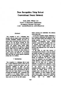
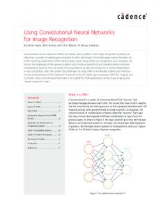
translation rotation scale
Figure 1: The principle of face alignment. Left: bounding rectangle of face detector, right: rectangle aligned with face.
only cope with relatively little variations and, in practice, cannot effectively deal with imprecisely localized face images like those coming from a robust face detection systems. For this reason, most of the face recognition methods require an intermediate step, called face alignment or face registration, where the face transformed in order to be well-aligned with the respective bounding rectangle, or vice versa. Figure 1 illustrated this. Existing approaches can be divided into two main groups: approaches based on facial feature detection and global matching approaches, most of the published methods belonging to the first group. Berg et
ROBUST FACE ALIGNMENT USING CONVOLUTIONAL NEURAL NETWORKS
al. (Berg et al., 2004), for example, used a SVMbased feature detector to detect eye and mouth corners and the nose and then applied an affine transformation to align the face images such that eye and mouth centers are at pre-defined positions. Wiskott et al. (Wiskott et al., 1997) used a technique called Elastic Bunch Graph Matching where they mapped a deformable grid onto a face image by using local sets of Gabor filtered features. Numerous other methods (Baker and Matthews, 2001; Edwards et al., 1998; Hu et al., 2003; Li et al., 2002) align faces by approaches derived from the Active Appearance Models introduced by Cootes et al. (Cootes et al., 2001). Approaches belonging to the second group are less common. Moghaddam and Pentland (Moghaddam and Pentland, 1997), for example, used a maximum likelihood-based template matching method to eliminate translation and scale variations. In a second step, however, they detect four facial features to correct rotation as well. Jia et al. (Jia et al., 2006) employed a tensor-based model to super-resolve face images of low resolution and at the same time found the best alignment by minimizing the correlation between the low-resolution image and the super-resolved one. Rowley et al. (Rowley et al., 1998) proposed a face detection method including a Multi-Layer Perceptron (MLP) to estimate in-plane face rotation of arbitrary angle. They performed the alignment on each candidate face location and then decided if the respective image region represents a face. The method proposed in this paper is similar to the one of Rowley et al. (Rowley et al., 1998) but it not only corrects in-plane rotation but also x/y translation and scale variations. It is further capable of treating non-frontal face images and employs an iterative estimation approach. The system makes use of a Convolutional Neural Network (CNN) (LeCun, 1989; LeCun et al., 1990) that, after being trained, receives a mis-aligned face image and directly and simultaneously responds with the respective parameters of the transformation that the input image has undergone. The remainder of this article is organized as follows. In sections 2 and 3, we describe the neural network architecture and training process. Section 4 gives details about the overall alignment procedure and in section 5 we experimentally assess the precision and the robustness of the proposed approach. Finally, conclusions are drawn in section 6.
2
THE PROPOSED SYSTEM ARCHITECTURE
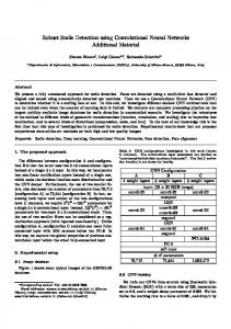
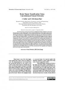
The proposed neural architecture is a specific type of neural network consisting of seven layers, where the first layer is the input layer, the four following layers are convolutional and sub-sampling layers and the last two layers are standard feed-forward neuron layers. The aim of the system is to learn a function that transforms an input pattern representing a mis-aligned face image into the four transformation parameters corresponding to the misalignment, i.e. x/y translation, rotation angle and scale factor. Figure 2 gives an overview of the architecture. The retina l1 receives a cropped face image of 46 × 56 pixels, containing gray values normalized between −1 and +1. No further pre-processing like contrast enhancement, noise reduction or any other kind of filtering is performed. The second layer l2 consists of four so-called feature maps. Each unit of a feature map receives its input from a set of neighboring units of the retina as shown in Fig. 3. This set of neighboring units is often referred to as local receptive field, a concept which is inspired by Hubel and Wiesel’s discovery of locally-sensitive, orientation-selective neurons in the cat visual system (Hubel and Wiesel, 1962). Such local connections have been used many times in neural models of visual learning (Fukushima, 1975; LeCun, 1989; LeCun et al., 1990; Mozer, 1991). They allow extracting elementary visual features such as oriented edges or corners which are then combined by subsequent layers in order to detect higher-order features. Clearly, the position of particular visual features can vary considerably in the input image because of distortions or shifts. Additionally, an elementary feature detector can be useful in several parts of the image. For this reason, each unit shares its weights with all other units of the same feature map so that each map has a fixed feature detector. Thus, each feature map y2i of layer l2 is obtained by convolving the input map y1 with a trainable kernel w2i : y2i (x, y) = ∑ w2i (u, v) y1 (x + u, y + v) + b2i , (1) (u,v)∈K
where K = {(u, v) | 0 < u < sx ; 0 < v < sy } and b2i ∈ R is a trainable bias which compensates for lighting variations in the input. The four feature maps of the second layer perform each a different 7 × 7 convolution (sx = sy = 7). Note that the size of the obtained convolutional maps in l2 is smaller than their input map in l1 in order to avoid border effects in the convolution. Layer l3 sub-samples its input feature maps into maps of reduced size by locally summing up the out-
31
VISAPP 2008 - International Conference on Computer Vision Theory and Applications
convolution 5x5 convolution 7x7 subsampling subsampling
Translation X Translation Y Rotation angle Scale factor
l3 : 4x20x25
l1 : 1x46x56 l2 : 4x40x50
l5 : 3x8x10
l4 : 3x16x21
l7 : 4 l6 : 40
Figure 2: Architecture of the neural network.
subsampling convolution 5x5
Figure 3: Example of a 5 × 5 convolution map followed by a 2 × 2 sub-sampling map.
put of neighboring units (see Fig. 3). Further, this sum is multiplied by a trainable weight w3 j , and a trainable bias b3 j is added before applying a sigmoid activation function Φ(x) = arctan(x): � y3 j (x, y) = Φ w3 j
∑
u,v∈{0,1}
� y2 j (2x + u, 2y + v) + b3 j .
(2) Thus, sub-sampling layers perform some kind of averaging operation with trainable parameters. Their goal is to make the system less sensitive to small shifts, distortions and variations in scale and rotation of the input at the cost of some precision. Layer l4 is another convolutional layer and con-
32
sists of three feature maps, each connected to two maps of the preceding layer l3 . In this layer, 5 × 5 convolution kernels are used and each feature map has two different convolution kernels, one for each input map. The results of the two convolutions as well as the bias are simply added up. The goal of layer l4 is to extract higher-level features by combining lowerlevel information from the preceding layer. Layer l5 is again a sub-sampling layer that works in the same way as l3 and again reduces the dimension of the respective feature maps by a factor two. Whereas the previous layers act principally as feature extraction layers, layers l6 and l7 combine the extracted local features from layer l4 into a global model. They are neuron layers that are fully connected to their respective preceding layers and use a sigmoid activation function. l7 is the output layer containing exactly four neurons, representing x and y translation, rotation angle and scale factor, normalized between −1 and +1. After activation of the network, these neurons contain the estimated normalized transformation parameters y7i of the mis-aligned face image presented at l1 . Each final transformation parameter pi is then calculated by linearly rescaling the corresponding value y7i from [-1,+1] to the interval of
ROBUST FACE ALIGNMENT USING CONVOLUTIONAL NEURAL NETWORKS
Face Detection
Face extraction and rescaling
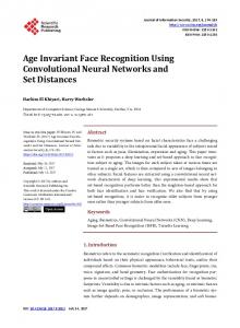
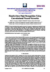
Figure 4: Examples of training images created by manually misaligning the face (top left: well-aligned face image). Alignment estimation by CNN
Translation X = − 2 Translation Y = +4 Rotation angle = −14 Scale factor = 0.95
the respective minimal and maximal allowed values pmini and pmaxi : pi =
3
pmaxi − pmini (y7i + 1) + pmini , i = 1..4 . 2 (3)
Adjust by 10% using the inverse parameters
TRAINING PROCESS
no
We constructed a training set of about 30,000 face images extracted from several public face databases with annotated eye, nose and mouth positions. Using the annotated facial features, we were able to crop wellaligned face images where the eyes and the mouth are roughly at pre-defined positions in the image while keeping a constant aspect ratio. By applying transformations on the well-aligned face images, we produced a set of artificially mis-aligned face images that we cropped from the original image and resized to have the dimensions of the retina (i.e. 46 × 56). The transformations were applied by varying the translation between −6 and +6 pixels, the rotation angle between −30 and +30 degrees and the scale factor between 0.9 and 1.1. Figure 4 shows some training examples for one given face image. The respective transformation parameters pi were stored for each training example and used to form the corresponding desired outputs of the neural network by normalizing them between −1 and +1: di =
2 (pi − pmini ) −1 . pmaxi − pmini
(4)
Training was performed using the well-known Backpropagation algorithm which has been adapted in order to account for weight sharing in the convolutional layers (l2 and l4 ). The objective function is simply the Mean Squared Error (MSE) between the computed outputs and the desired outputs of the four neurons in l7 . At each iteration, a set of 1,000 face images is selected at random. Then, each face image example of this set and its known transformation
30 iterations ? yes
Save final parameters
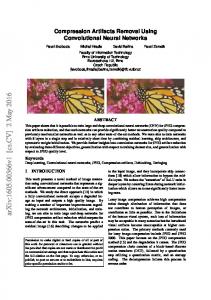
Figure 5: Overall alignment procedure.
parameters are presented, one at a time, to the neural network and the weights are updated accordingly (stochastic training). Classically, in order to avoid overfitting, after each training iteration, a validation phase is performed using a separate validation set. A minimal error on the validation set is supposed to give the best generalization, and the corresponding weight configuration is stored.
4
ALIGNMENT PROCESS
We now explain how the neural network is used to align face images with bounding boxes obtained from a face detector. The overall procedure is illustrated in Figure 5. Face detection is performed using the Convolutional Face Finder by Garcia and Delakis (Garcia and Delakis, 2004) which produces upright bounding boxes. The detected faces are then extracted according to the bounding box and resized to 46 × 56 pixels. For each detected face, the alignment process is performed by presenting the mis-aligned cropped face image to the trained neural network which in turn gives an estimation of the underlying transformation.
33
VISAPP 2008 - International Conference on Computer Vision Theory and Applications
A correction of the bounding box can then simply be achieved by applying the inverse transformation parameters (−pi for translation and rotation, and 1/pi for scale). However, in order to improve the correction, this step is performed several (e.g. 30) times in an iterative manner, where at each iteration, only a certain proportion (e.g. 10%) of the correction is applied to the bounding box. Then, the face image is re-cropped using the new bounding box and a new estimation of the parameters is calculated with this modified image. The transformation with respect to the initial bounding box is obtained by simply accumulating the respective parameter values at each iteration. Using this iterative approach, the system finally converges to a more precise solution than when using a full one-step correction. Moreover, oscillations can occur during the alignment cycles. Hence, the solution can further be improved by reverting to that iteration where the neural network estimates the minimal transformation, i.e. where the outputs y7i are the closest to zero. The alignment can be further enhanced by successively executing the procedure described above two times with two different neural networks: the first one trained as presented above for coarse alignment and the second one with a modified training set for fine alignment. For training the fine alignment neural network, we built a set of face images with less variation, i.e. [−2, +2] for x and y translations, [−10, +10] for rotation angles and [0.95, 1.05] for scale variation. As with the neural network for coarse alignment, the values of the output neurons and the desired output values are normalized between −1 and +1 using reduced extrema pmin′i and pmax′i (cf. equation 4).
5
EXPERIMENTAL RESULTS
To evaluate the proposed approach, we used two different annotated test sets, the public face database BioID (available at h t t p : / / www.humanscan.com/support/downloads /facedb.php) containing 1,520 images and a private set of about 200 images downloaded from the Internet. The latter, referred to as Internet test set, contains face images of varying size, with large variations in illumination, pose, facial expressions and containing noise and partial occlusions. As described in the previous section, for each face localized by the face detector (Garcia and Delakis, 2004), we perform the alignment on the respective bounding box and calculate the precision error e which is defined as the mean of the distances between its corners ai ∈ R2 and the respective corners of the desired bounding
34
box bi ∈ R2 normalized with respect to the width W of the desired bounding box: e=
1 4W
4
∑ kai − bik
.
(5)
i=1
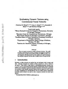
Figure 6 shows, for the two test sets, the proportion of correctly aligned faces varying the allowed error e. For example, if we allow an error of 10% of the bounding box width, 80% and 94% of the faces of the Internet and BioID test sets respectively are wellaligned. Further, for about 70% of the aligned BioID faces, e is below 5%. We also compared our approach to a different technique (Duffner and Garcia, 2005) that localizes the eye centers, the nose tip and the mouth center. The face images with localized facial features are aligned using the same formula as used for creating the training set of the neural network presented in this paper. Figure 7 shows the respective results for the Internet test set. To show the robustness of the proposed method, we added Gaussian noise with varying standard deviation σ to the input images before performing face alignment. Figure 8 shows the error e versus σ, averaged over the whole set for both of the test sets. Note that e remains below 14% for the Internet test set and below 10% for the BioID test set while adding a large amount of noise (i.e. σ up to 150 for pixel values being in [0, 255]). Another experiment demonstrates the robustness of our approach against partial occlusions while adding black filled rectangles of varying area to the input images. Figure 9 shows, for two types of occlusions (explained below), the error e averaged over each test set with varying s, representing the occluded proportion with respect to the whole face rectangle. For a given detected face, let w be the width and h be the height of the bounding box. The first type of occlusion is a black strip (”scarf”) of width w and varying height h at the bottom of the detected face rectangle. The second type is a black box with aspect ratio w/h at a random position inside the detected rectangle. We notice that while varying the occluded area up to 40% the alignment error does not substantially increase, especially for the scarf type. It is, however, more sensitive to random occlusions. Nevertheless, for s < 30% the error stays below 15% for the Internet test set and below 12% for the BioID test set. Figure 10 shows some results on the Internet test set. For each example, the black box represents the desired box, while the white box on the respective left image represents the face detector output and the one
1
1
0.9
0.9
0.8
0.8
0.7
0.7
Rate of correct alignment
Rate of correct alignment
ROBUST FACE ALIGNMENT USING CONVOLUTIONAL NEURAL NETWORKS
0.6 0.5 0.4 0.3 0.2
0.6 0.5 0.4 0.3 0.2
0.1
0.1
Internet test set BioID test set
0 0
0.05
0.1
0.15
0.2
0.25
0.3
0.35
0.4
Feature detection approach Our approach
0
0.45
0.5
0
0.05
0.1
0.15
Mean corner distance: e
0.25
0.3
0.35
0.4
0.45
0.5
Mean corner distance: e
Figure 6: Correct alignment rate vs. allowed mean corner distance.
Figure 7: Precision of our approach and an approach based on facial feature detection (Duffner and Garcia, 2005).
0.2
0.2
0.15
0.15
mean e
mean e
0.2
0.1
0.05
0.1
0.05
Internet BioID
0 0
20
40
60 80 standard deviation
100
120
Internet: random rectangle Internet: scarf BioID: random rectangle BioID: scarf
0 140
0
0.05
0.1
0.15 0.2 0.25 occluded porportion s
0.3
0.35
0.4
Figure 8: Sensitivity analysis: Gaussian noise.
Figure 9: Sensitivity analysis: partial occlusion.
on the respective right image represents the aligned rectangle as estimated by the proposed system. The method is also very efficient in terms of computation time. It runs at 67 fps on a Pentium IV 3.2GHz and can easily be implemented on embedded platforms.
of up to ±13% of the face bounding box width, inplane rotations of up to ±30 degrees and variations in scale from 90% to 110%. In our experiments, 94% of the face images of the BioID database and 80% of a test set with very complex images were aligned with an error of less than 10% of the bounding box width. Finally, we experimentally show that the precision of the proposed method is superior to a feature detection-based approach and very robust to noise and partial occlusions.
6
CONCLUSIONS
We have presented a novel technique that aligns faces using their respective bounding boxes coming from a face detector. The method is based on a convolutional neural network that is trained to simultaneously output the transformation parameters corresponding to a given mis-aligned face image. In an iterative and hierarchical approach this parameter estimation is gradually refined. The system is able to correct translations
35
VISAPP 2008 - International Conference on Computer Vision Theory and Applications
Figure 10: Some alignment results with the Internet test set.
36
ROBUST FACE ALIGNMENT USING CONVOLUTIONAL NEURAL NETWORKS
REFERENCES Baker, S. and Matthews, I. (2001). Equivalence and efficiency of image alignment algorithms. In Computer Vision and Pattern Recognition, volume 1, pages 1090–1097. Berg, T., Berg, A., Edwards, J., Maire, M., White, R., Teh, Y.-W., Learned-Miller, E., and Forsyth, D. (2004). Names and faces in the news. In Computer Vision and Pattern Recognition, volume 2, pages 848–854. Cootes, T., Edwards, G., and Taylor, C. (2001). Active appearance models. IEEE Transactions on Pattern Analysis and Machine Intelligence, 23(6):681–685. Duffner, S. and Garcia, C. (2005). A connexionist approach for robust and precise facial feature detection in complex scenes. In Fourth International Symposium on Image and Signal Processing and Analysis (ISPA), pages 316–321, Zagreb, Croatia. Edwards, G., Taylor, C., and Cootes, T. (1998). Interpreting face images using active appearance models. In Automatic Face and Gesture Recognition, pages 300–305. Fukushima, K. (1975). Cognitron: A self-organizing multilayered neural network. Biological Cybernetics, 20:121–136. Garcia, C. and Delakis, M. (2004). Convolutional face finder: A neural architecture for fast and robust face detection. IEEE Transactions on Pattern Analysis and Machine Intelligence, 26(11):1408 – 1423. Hu, C., Feris, R., and Turk, M. (2003). Active wavelet networks for face alignment. In British Machine Vision Conference, UK. Hubel, D. and Wiesel, T. (1962). Receptive fields, binocular interaction and functional architecture in the cat’s visual cortex. Journal of Physiology, 160:106–154. Jia, K., Gong, S., and Leung, A. (2006). Coupling face registration and super-resolution. In British Machine Vision Conference, pages 449–458, Edinburg, UK. LeCun, Y. (1989). Generalization and network design strategies. In Pfeifer, R., Schreter, Z., Fogelman, F., and Steels, L., editors, Connectionism in Perspective, Zurich. LeCun, Y., Boser, B., Denker, J., Henderson, D., Howard, R., Hubbard, W., and Jackel, L. (1990). Handwritten digit recognition with a back-propagation network. In Touretzky, D., editor, Advances in Neural Information Processing Systems 2, pages 396–404. Morgan Kaufman, Denver, CO. Li, S., ShuiCheng, Y., Zhang, H., and Cheng, Q. (2002). Multi-view face alignment using direct appearance models. In Automatic Face and Gesture Recognition, pages 309–314. Martinez, A. (2002). Recognizing imprecisely localized, partially occluded, and expression variant faces from a single sample per class. IEEE Transactions on Pattern Analysis and Machine Intelligence, 24(6):748–763. Moghaddam, B. and Pentland, A. (1997). Probabilistic visual learning for object representation. IEEE Transactions on Pattern Analysis and Machine Intelligence, 19(7):696–710.
Mozer, M. C. (1991). The perception of multiple objects: a connectionist approach. MIT Press, Cambridge, USA. Rentzeperis, E., Stergiou, A., Pnevmatikakis, A., and Polymenakos, L. (2006). Impact of face registration errors on recognition. In Artificial Intelligence Applications and Innovations, Peania, Greece. Rowley, H. A., Baluja, S., and Kanade, T. (1998). Rotation invariant neural network-based face detection. In Computer Vision and Pattern Recognition, pages 38– 44. Shan, S., Chang, Y., Gao, W., Cao, B., and Yang, P. (2004). Curse of mis-alignment in face recognition: problem and a novel mis-alignment learning solution. In Automatic Face and Gesture Recognition, pages 314–320. Wiskott, L., Fellous, J., Krueger, N., and von der Malsburg, C. (1997). Face recognition by elastic bunch graph matching. IEEE Transactions on Pattern Analysis and Machine Intelligence, 19(7):775–779.
37