Robust fractional order controller for a linear active magnetic bearing system Tomasz Nartowicz1, Ewa Pawluszewicz2, Arkadiusz Mystkowski3 Department of Automatic Control and Robotics Bialystok University of Technology Wiejska 45C, 15-351 Bialystok, Poland 1
[email protected],
[email protected],
[email protected] ― corresponding author
The aim of the paper is to present some new results of practical study with unstable current-controlled active magnetic bearing model. Moreover, the robustness analysis for the parameter uncertainty of the AMB system is given.
Abstract−In the paper the fractional order PID feedback control loop is designed in order to stabilize the unstable linear current-controller active magnetic bearing (AMB) system. The review for stability analysis of fractional continuous-time linear systems described by the transfer functions is given. The specified fractional order controllers, obtained for desired different phase margins, are verified by means of numerical simulations. The robust stability of fractional order PID feedback-loop is shown due to AMB parametric uncertainty.
2.
INTEGRO-
In the general case a fractional order operator of a complex order , can be defined as (see for example [9]):
Keywords: fractional order controller, PID controller, active magnetic bearing, current-control, parametric uncertainty.
( )>0 :=
1. INTRODUCTION
1 (
The first and the most important step, during control system design process, is the development of an appropriate and suitable mathematical model of the analysed control plant. Such model can be derived either from physical laws or from experimental data and identification process. Compared with classical integer models, fractional models often provide good tools for description of properties of various systems, see for example in [1, 2]. The fractional order control (FOC) approach is used to design control systems and controllers. Fractional order of derivatives and integrals has long standing theoretical foundation. The beginning of fractional calculus is dated on 1695. The ground for a fractional calculus was given by Liouville, Holmgren and Riemann, Grunwald, Letnikov, Riemann and others see for example [3, 4]. At the same time, when theoretical beginnings were given, applying the fractional calculus to various problems were developed. As the first was Abel who in 1823 found the solution of the integral equation for the tautochrone. This result occurred more economical and useful than the conventional integer order approach [4]. In last decades problem of synthesis and analysis of control systems described by fractional order differential or difference equations was considered by many authors, see for example [1, 2, 5, 6, 7].
978-1-5386-2402-9/17/$31.00 ©2017 IEEE
FRACTIONAL ORDER DIFFERENTIAL OPERATORS
(1)
( )=0 )
( ) 0. The Laplace transform of this operator is given as ℒ
( ) =
( )−
[
( )] (3)
where ( ) = ℒ[ ( )] and ∈ ℂ denotes the Laplace transform of the function ( ). It can be observe that in order to realize fractional order controllers perfectly, all the past input should be memorized. In practice often it is not possible. Therefore a proper
658
approximation or discretization method should be used. The most commonly used discretization approach in fractional case is termed as short memory principle, see [10]. It is based on the fractional order Grünwald–Letnikov (GL) operator of order ∈ ( − 1, ), (see for example [1, 2, 5]): ∑
( ): = lim →
(−1)
order, that is all orders of derivation in (7) are integer multiplies of a base order , ∈ ℝ . Then, substituting = , the transfer function (8) of the system (7) with respect to zero initial conditions can be written in the form:
( − ℎ) (4)
( )=
)…(
=
)
for = 1,2,3, . . , for = 0
!
1
(9)
...
Then, taking into account again that
where ℎ > 0 and (
...
( )=
=
we obtain:
∑
(10) , = 1,2, … , .
with constant coefficients ,
denotes the binomial coefficient.
4.
Since values of the binomial coefficient near “starting point” = 0 are small enough to be neglected, see [10]. It is easy
Generalization of the concept of the classical PID controller on the concept of FOPID (fractional order PID) controller leads to:
( )= ( ) for any to note also that continuously differentiable function . In the following, if it is just not misleading, we are going to skip symbols RL or GL in fractional order differential operators.
( )=
is given by, see [10] ( )] = ℎ
Ƶ[D
where ( ) = Ƶ[ ( )],
∑
=
(−1)
and
( ) (5)
( )≔∑
is the number of past
with 3.
( )
=
(
)
( )
( − ℎ)
( )=
(6)
A continuous time linear input-output system can be described as linear fractional differential equation of order , > 0, of one (time) variable: (7)
... ...
is the gain crossover frequency (
( )=
> >∙∙∙> > ≥ 0, > >∙∙∙> where > ≥ 0 are real numbers, , , ∈ = 0,1, … , , = 0,1, , … , . The transfer function of the considerate system is of the form: ( )=
(13) = 1).
The control system described by (12) has the constant value of phase margin = (1 − 0.5 ) . Hence, such system is unsensitive to the gain changes in the open loop system. In effect, to obtain the ideal Bode transfer function in open loop system, the controller transfer function should have a structure:
TRANSFER FUNCTION
( )
(12)
( )= where
( )=∑
(11)
where denotes a static gain, T − time constant, and is positive real number. Transfer function of the proposed controller follows directly from the using of Bode's ideal transfer function as a reference transfer function for the open loop system
, see [11].
∑
+
Let the control plant be described by the following transfer function
values taken into account (so called memory of the system). In practice application formula (5) leads to Grünwald−Letnikov type fractional ℎ − difference operator of the real function defined on the set (ℎ ) : = { , + ℎ, + 2ℎ, … } ∆
+
where and are allowed to be noninteger positive real denote respectively the proportional, numbers, , , integral and differential gains, see for example in [1, 6]. Design of the FOPID satisfying given stability margin, in the closed loop system has been realized.
The discrete equivalent of the fractional-order differential operator
FRACTIONAL ORDER PID CONTROLLER
+
+
=
(14)
Assuming that + + = − , the transfer function for the open loop system with the control plant (12) and the fractional order controller (14) is given by: ( )= ( ) ( )=
(8)
(15)
Note that equation (15) has a form of considered Bode's
We assume that the system (7) is of the commensurate
659
see [13, 14].
ideal transfer function (13), so the constant value of phase margin should be = (1 − 0.5 ) .
The linear open-loop model of the 1−DOF AMB for one control axis is called here the nominal model and is given by [14]
Let us analyse the process of design the fractional order controller with transfer function (14). Due to the given phase margin , the controller parameter is searching. / Knowing that ( ) = | | gain and phase for a transfer function (12) can be written respectively as: | ( For a gain given as:
For a given
)| =
( ) = arg
,
and
=2−
) =−
= 1,
= arg
gain and
phase margins we have: =
and
=−
−
.
(17)
=
(18)
(19)
and from the transfer function of the controller (14) it follows that: (s) =
+
+
,
+√
−√
(20)
−
(21)
.
( )=
and comparing coefficients of (20) and (21) we can note that =√ , = and = . =2− ,
(23)
.
(24)
and is rewritten in the form: ( )≅
Note also that the open loop transfer function differs from −√ , what Bode’s ideal transfer function (13) with √ follows directly from (21). It will make a difference in the real phase margin of the closed loop system with the control plant transfer function (12) and controller (14). 5.
=
,
The linear model of the current-controlled AMB is obtained in the operating point (x0, i0) defined by the nominal clearance = 0.0004 m and bias coil current = 2 A. The transfer function of the AMB nominal model is given by:
then assuming that − =
(22)
where ki0 denotes the nominal current stiffness [N/A], ks0 – displacement stiffness [N/m], μ0 – permeability of free space [H/m], N – number of coils, A – pole of cross-section of stator [m2], i0 – bias coil current [A], x0 – nominal air gap [m].
Since (12) implies that: −
=
( )
The transfer function (22) describing the relation between control current is and measured displacement x of the rotor is derived for some operation point (x0, i0). The main nominal parameters of the AMB model (22) are given by:
.
(s) =
( )
where ki denotes the current stiffness [N/A], ks – displacement stiffness [N/m], m – rotor mass reduced to the bearing plane [kg].
(16)
phase crossover frequency terms is
= So
(
( )=
. .
(25)
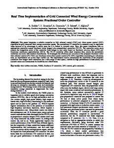
The radial AMB view is given in Fig. 1. For detailed description of the 5−DOF AMB test rig we refer the reader to [13]. The general specification of the radial AMB with main data is given in Table I.
CURRENT-CONTROLLED AMB SYSTEM
AMBs have growing potential and together with proper intelligent control system they can be used in many applications if the overall cost of the systems are reduced. However, major challenges are related to realization of the measurement and control system [12]. In current-controlled AMB system, the control currents are as inputs and rotor position is as output. In AMB, the electromagnetic force is nonlinear function of coil current and rotor displacement. The model of plant with nominal parameters is called a nominal model. The values of nominal parameters are calculated for some operating point. The AMB control system with classical large bias current is a well-known linear control problem, and as a result, PID controllers, ℋ – based control and μ-synthesis methods can be applied, e.g.,
Fig. 1. Radial AMB with Hall and eddy-current sensors
660
and rotor displacements. In the current-controlled AMB system, the uncertain parameters are and . In our case and are equal to 13.3 [N/A] the nominal values of and 66 559.0 [N/m] respectively. The uncertainties of the parameters and are given as follows:
TABLE I. Radial AMB system specification parameter
value, [unit]
number of poles
8
angle between the poles
22.5°
cross-sectional area of the pole piece
0.000360 [m2]
number of turns of one pair of coils
70
nominal air gap
0.0004 [m]
maximum current
5 [A] (10 [A] impulse)
bias current
2 [A]
coil resistance
0.26 [Ω]
coil inductance
0.0028 [H]
permeability of free space
1.25×10⁻⁶ [H/m]
rotor mass in one AMB plane
3 [kg]
current stiffness
13.3 [N/A]
displacement stiffness
66 559.0 [N/m]
displacement sensor gain
7 920
= = where and uncertain parameters
40
fractional order
1.55
parameter
60
1.33
( ) = 14 +
80
1.11
( ) = 14 +
196 .
and fractional
196 .
196 .
[N/A]
13.3
5.9
53.2
[N/m]
66 559.0
1 9721.2
532 472.4
For minimum and maximum values of the uncertain parameters (given in Table III), the AMB model values ranges are given by ( )=
+ 0.0044
.
+ 0.0044
.
+ 0.0044
.
boundary value min. max.
nominal value
The weighting functions and are the constant gains depend on the AMB parameters (see Table I), selected and (given by (23)). Its according to the parameters deviations are presented in Table III. The values of the and in our case are equal to 1.
controller ( ) = 14 +
are the weighting functions of the and , respectively.
TABLE III. Boundary values of uncertain parameters
Different phase margins are specified for the fractional order PID controllers in Table II. For the AMB model (25) by using (14) and (18)−(21), we found for each desired values of , the fractional order PID controller parameter . Note, = 14, = 196 and that for the model (25) we have = 0.0044.
phase margin [deg]
(26)
The deviation of these parameters was calculated for the case when the rotor rests on the back up bearings (ball bearings) with clearance of = 0.5 . For this purpose the minimum and maximum rotor displacement from the origin ( = 0) is given by = ± (where for = 0.0004, we have: = 0.0002 and = 0.0006). The ranges of uncertain parameters are shown in Table III.
A. Fractional order PID controller
TABLE II. Relations between phase margin order of the controller (14)
for | | ≤ 1 for | | ≤ 1
+ +
6.
.
,
( )=
.
(27)
SIMULATION RESULTS
This section presents simulation results for the active magnetic bearing (AMB) system controlled with fractional order PID feedback loop. Particularly, the robustness analysis of the FPID feedback loop of the current-controlled AMB with parameter varying is presented. Numerical calculations of the control system using FPID controller are carried out using Matlab/Simulink software. In order to estimate non integer terms, the function provides integer approximations of fractional PID controller with CRONE formula, were used [15].
B. AMB system with parameter uncertainty The nominal model has to reflect the real plant as exactly as possible. When the model of the control plant corresponds to the real plant, the magnitude of the model uncertainties (structural, dynamic or parametric) is small.
In numerical calculations the AMB closed-loop representations includes the AMB nominal model (25) or the boundary AMB models (27) (obtained for boundary
In the AMB system the current and position stiffness are very sensitive parameters. They depend on control current
661
nominal one) are stable, and the closed-loop system has the biggest bandwidth of 3020 rad/s.
values of the uncertain parameters) together with the controllers (given in Table II) and rotor mass displacement sensor gain (given in Table I).
From: ccurrent To: rdisplacement
In results of the computer simulation the step responses of the consider closed-loop systems with different parameters of the fractional order controller are obtained. All the AMB closed-loop systems are asymptotically stable in spite of bounded external disturbances and parametric uncertainty. The AMB closed-loop systems responses to the step current disturbance are given in Fig. 2. Particularly, we can observe the rotor displacement oscillations. The vibration amplitude coverage to zero with the time. Note that, for the disturbance amplitude equal to 50% of the nominal coil current, maximum amplitude of the rotor displacement does not exceed 2 × 10 [m] which means 20% of the nominal air gap. The setting time is equal to 0.7 sec, 0.2 sec and 0.1 sec for system’s phase margin = 40°, = 60°, = 80°, respectively.
Magnitude (dB)
−60
0.8
Phase (deg)
1
0.6
0.8
1 λ=1.11
0.2
0.4
0.6
0.8
0.4
0.6
0.8
−135 3
4
10 Frequency (rad/s)
10
x 10
1
0.2
0.4
0.6
0.8
1 Gmax
0 0.2
0.4
0.6
0.8
1 Gmin
0 −2 0
Fig. 2. Step current disturbance response for nominal systems with different controller order
Gnominal
0
−2 0 −5 x 10 2
1
disturbance current [A] 0.2
φm=80o
−90
−2 0 −5 x 10 2
x [m]
0.4
φm=60o
−45
−5
λ=1.33 0.2
φm=40o
0
2
x [m]
0.6
−140
Fig. 3. Bode diagram of the nominal systems for different phase margins
x [m]
x [m] x [m] x [m] id [A]
1 0.5 0 0
0.4
−120
−180 2 10
λ=1.55 0.2
−100
−160 45
−5
x 10 2 0 −2 0 −5 x 10 2 0 −2 0 −5 x 10 2 0 −2 0
−80
0.2
0.4
0.6
0.8
1
time [s]
Fig. 4. Step current disturbance response ( ) for nominal system and for boundary systems
Fig. 3 shows the Bode diagrams of the nominal closed-loop AMB systems. The system with phase margin = 40° has the biggest eigenvalue peak of -60.7 dB at 976 rad/s whereas the system with = 80° has eigenvalue peak of 82.8 dB at 1010 rad/s.
Bode Diagram
Magnitude (dB)
−80
Fig. 4 shows the nominal and boundary AMB closed-loop systems responses to the step current disturbance (presented in Fig. 2). In spite of the uncertain parameters of and the AMB closed-loop systems at the boundary values are robustly stable due to current control step disturbance.
−100 −120 −140
Phase (deg)
−160 45
Fig. 5 presents Bode diagrams for nominal and boundary closed-loop systems (obtained for boundary values of the uncertain parameters) with the controller order = 1.11. The boundary systems and have eigenvalues peaks of -80.4 dB at frequency 649 rad/s and -89.4 dB for 2020 rad/s respectively. All these systems (together with the
Gnominal
0
Gmax
−45
Gmin
−90 −135 −180 2 10
3
10 Frequency (rad/s)
4
10
Fig. 5. Bode diagram of the nominal system and for boundary systems for phase margins = 80°
662
The poles distributions for the AMB nominal closed-loop system for different phase margins are given in Fig. 6.
REFERENCES [1] [2]
Pole−Zero Map 1500
0.04
0.027
Imaginary Axis (seconds−1)
3 1000 0.065
500
0.019
[3]
1.4e+03 0.013 0.0085 0.004 1.2e+03
2
1 1e+03
stability margin
800
[4]
600
0.12
400
[5]
200
3
0
21
[6]
200 −500
400
0.12
−1000 0.065
800 1
[8]
1e+03 0.04
−1500 −70
[7]
600
2
3
−60
0.027 −50
0.019
−40 −30 −1 Real Axis (seconds )
1.2e+03 0.013 0.0085 0.004 1 4e+03 −20 −10 0
[9]
Fig. 6. Pole map of the nominal systems {with poles denote to the system no: 1, 2, 3} for the different phase margins = 40°, 60°, 80°} respectively {
[10]
Particularly, only the dominate poles are presented in the map shown in Fig. 6. Note, that the AMB transfer function model (25) is unstable and has two poles at , = ∓210.6 + 0. The AMB closed-loop systems with controllers (given in Table II) have all poles the stable. The natural frequency of these poles increases with the phase margin and systems increase stability margins. 7.
[11]
[12] [13]
CONCLUSIONS [14]
In the paper the robust FOPID controller was proposed for the unstable linear model of the current-controlled active magnetic bearing. Stability of the proposed controllers, derived for the desired different phase margins, have been shown. The fractional order current-controlled AMB designs ensure robust stability in spite of parameter varying.
[15]
One of the future research into this topic is to check our approach by means of an experimental verification and measurements results on the 5–DOF AMB test rig. Moreover, we plan make future investigations which would extend proposed FPID feedback strategies to the voltage- or flux-controlled AMB systems. ACKNOWLEDGMENT
This work is supported with University Work no S/WM/1/2016 of Department of Automatic Control and Robotics, Bialystok University of Technology and also supported with Polish Ministry of Science and Higher Education.
663
Podlubny I., Fractional differential equations, Academic Press, San Diego, 1999. Das. S., Functional fractional calculus for system identification and controls, Springer, Berlin, 2008. Kilbas A.A., Srivastava H.M., Trujillo J.J., Theory and applications of fractional differential equations, Elsevier, Amsterdam, 2006. Oldham K.B,. Spaniel J., The fractional calculus, Academic Press, New York and London, 1974. Kaczorek T., Selected problems of fractional systems theory, Springer, 2011. Ostalczyk P., Ephitome of fractional calculus, Press Lodz Lodz University of Technology, 2008. Oustaloup A., Diversity and non-integer differentiation for system dynamics, Wiley 2014. Agrawal O.P., Generalized multiparameters fractional variational calculus, International Journal of Differential Equations, 2012, 521750, 0−38. Matasu R., Application of fractional order calculus to control theory, International Journal of Mathematical Models and Methods in Applied Sciences, 2012, 5(7), 1162−1169. Bandyopadhyay B., Kamal S., Stabilization and control of fractional order systems: a sliding mode approach, Lecture Notes in Electrical Engineering, Springer International Publishing, 2015. Girejko E., Mozyrska D., Wyrwas M., Comparison of hdifference fractional operators, Advances in the theory and applications of non-integer order systems, W. Mitkowski et al. (Eds.), 2013, 191−197. G. Schweitzer, E. Maslen–Eds., Magnetic bearings: theory, design, and application to rotating machinery, Springer, Berlin-Heidelberg, 2009. Gosiewski Z and Mystkowski A., The robust control of magnetic bearings for rotating machinery, Solid State Phenomena, 2006, 113, 125−130. Gosiewski Z and Mystkowski A. Robust control of active magnetic suspension: analytical and experimental results. Mechanical Systems & Signal Processing 2008, 22, 1297– 1303. Valerio D., Costa J.S., Ninteger: a non-integer control toolbox for matlab. In 1st IFAC Workshop on Fractional Differentiation and its Applications, Bordeaux, France, 2004.


![Fractional-Order [Proportional Derivative] Controller for Robust Motion ...](https://m.moam.info/img/260x300/fractional-order-proportional-derivative-controlle_5bb87d99097c47550a8b4594.jpg)