The analysis of the controller shows that no limit cycle is introduced by the ... through experiments on rock samples., with and without lubricants. .... stability margin, such that (N, M, e,~ax) is robust- ly stable. ... actual system can be unstable, if the roll-off rate ..... transient stage is due to the increased inertia and friction of the ...
KSME International Journal, Vol. II, No. 1, pp. 45 ~ 55, 1997
45
Robust High-Gain Loop-Shaping Hoo Control of Servomechanisms Chintae Choi* and Jong Shik Kim** (Received April 29, 1996)
Loop-shaping tLo control with normalized coprime factorization is applied to a servo motor-driven precision positioning system. A high-gain controller is designed to attenuate the position errors caused by friction. The analysis of the controller shows that no limit cycle is introduced by the presence of actuator saturation. The designed [I= control system is experimentally tested on a rotary index table which requires a high-accuracy position control. The results show that the suggested control scheme improves the positional accuracy and its robustness to the model perturbation and external disturbances without any compensation scheme for friction. Key Words: Robust, H~, Control, Precision, Position.
I. Introduction High-speed/high-accuracy position-control systems are indispensible to the improvement of productivity as well as to the manufacture of precision products. While commonly neglected, because :it is difficult to model and poorly understood, friction is present to some degree in all mechanical systems, and continues to impose limits on performance. Mechanical systems are distinguished from other controlled plants by the presence of several significant nonlinearities such as static friction, Coulomb friction, backlash and actuator saturation. Among these nonlinearities, backlash may be reduced at the expense of increased stiction and Coulomb friction. The discontinuc,us nature of Coulomb-type friction near zero velocity causes stick-slip behavior which limits the fidelity of position and force control. As the performance criteria, such as cycle time, are made more stringent, the dynamic load dependency of friction becomes more influential. Stiction may cause steady-state error, or limil cycle near the reference position in the linear control of * Process Automation Team, RIST, Pohang, 790330, Korea ** School of Mechaical Engineering, Pusan National University, Pusan, 609-735, Korea
positioning system. Failure to account for the effects of friction can lead to tracking errors and oscillation. An adaptive pulse-width control scheme was proposed to achieve precise positioning in the presence of stiction and Coulomb friction (Yang and Tomizuka, (1990)). It is intended to be used near the reference position. Any conventional control law can be applied, until the system sticks near the reference position. When a motion stops and the error remains, a functional relationship between the pulse width and the error is updated by an adaptive algorithm, and a new pulse is applied. This sequence continues until the motion comes to a stop with :zero error. The adaptive fi:iction compensation at low velocities has been dealt with (Canudas de Wit, et al., ( 1 9 9 1 ) ) and a simple model, l i n e a r in parameters, that captures the downward bends at velocites close at zero was proposed. Ruina (1980) worked on the experimental and theoretical development of constitutive frictions, and suggested state variable friction models through experiments on rock samples., with and without lubricants. The ramifications of transient friction behavior as expressed by a state variable friction law for the control of low-velocity motion has also been explored (Dupont, (i[991)). A
46
Chintae Choi a n d ,long Shik Kirn
repititive control (Tung, et al., (1993)), a kind of learning control, was applied to compensate for stiction-induced errors which was a source of contouring errors in machine-tool systems. Ohnishi (1987) proposed a two-degree-offreedom controller using a disturbance observer. It estimates the disturbance and cancels the actual disturbance with the estimate. This method has a similar control structure to that of time delay control (Youcef-Toumi and lto, (1990)) and time delayed uncertainty cancellation (Hsia, et al., (1991)) in that the internal loop has a infinite loop gain as delay time becomes infinitely small. Lee and Tomizuka (1994) designed a control scheme for perfect tracking of a positioning system. The excellent performance achieved for certain parametric variations and external disturbances is due to an infinitely large bandwidth. Since the large bandwidth is inherent to the characteristics of the structure of the disturbance observer, this kind of the controller is very sensitive to measurement noise and is not robust against dynamic model uncertainties (Liang and
ed positions of servomechanisms accurately since positional errors are inversely proportional to the gain of the feedback controller. The high-gain controller results from a loop compensator with a large gain being selected in loop shaping so that the sensitivity function may have a small magnitude in the low-frequency region. Though the high-gain controller immediately saturates the actuators, the saturation does not give rise to a severe stability problem under the condition that the unstable poles and integrators are not included in the SISO closed-loop system. The designed high-gain controller has been tested experimentally on a rotary index table which requires a high-accuracy position control. To check for robust performance when parametric modelling errors exist, the tests were repeated with load variations.
Looze, (1992)). The normal forces orthogonal to the moving direction of the servomechanism, which determine the friction, constantly vary according to the temperature changes in the moving contacts and inertia perturbations of the masses attached to the moving mechanisms such as linear slide tables, index table, and so on. Beginning with Sampson, et al. (1943) and Rabinowitz (1959), it was noted that friction is not determined by the current velocity alone; it depends on the history of the motion and the instantaneous velocity change. In the environments where the dynamic normal force and the velocity direction are varying, it is very difficult to obtain an accurate model to completely cancel the effects of friction in servo systems. Therefore, it is more realistic to attenuate bounded friction sufficiently to the desired magnitude level than to resort to model-based compensation. This paper proposes an H= control scheme to compensate for the external disturbances including friction through a high-gain controller. The proposed scheme consequently controls the desir-
2.1. Normalized coprime factorization stabilization
2. Robust Controller D e s i g n Using Loop-Shaping
Let the nominal p • rn system, G, has a minimal state-space realization and normalized coprime factorization (NRCF) such that G(s)-
C(sI-
(1)
A)-IB
and (2)
G ( s ) = N M -~
Definition 1 : A right coprime factorization of G is normalized if the matrix [N~MT] ~ is inner. If X and Y > 0 are the solutions to the Riccati equations (Meyer, 1987) 0= A TX + XA- XBBTX + CrC 0=AY+ YA T- yCTCY+BB T
(3)
then the matix I N r M r ] v is easily determined from the following state-space realization.
F= - R-IBrX
=
O
(4)
I Then, any other perturbed system of the same input/output dimensions can be written in the
Robust High-Gain Loop-Shaping IJ~ Control of Servomechanisms form
G~ := ( N + AN)(M + AM)-~
(5)
where AN, and A M ~ H~ are stable transfer functions. The robust stabilization problem is to stabilize the nominal system, G, with N R C F ( N , M) and the fi~mily of systems G, using a proper feedback controller K .
Definition 2 (NRCF Robust Stabilization): Let (N, M ) be a N R C F of G, then 1) Find the largest positive number 6~ax called the maximum stability margin, such that (N, M, e,~ax) is robustly stable. 2) F o r a particular value 6'-
Fig. 3 Experimental setup of the servomechanism.
\
-60
the position sensor, which is an incremental encoder, is 5.992 • 10-6rad. The motor used is a DC servo motor, and the controller is implemented using an MVMEI43 computer that has a VME bus and a 32-bit microprocessor, MC68030, running at 25MHz. The computer is interfaced to a power amp via a DAC board and to an encoder through a counter board. The numerical values of the electrical and mechanical parameters of the used motor are listed in Table 1.
Table
1
Specifications of the motor
Motor model(Tamakawa)
TS1980
Moment of inertia
0.28 kg cm 2
Output power
100 W
Mechanical time constant
3.9 ms
Electrical time constant
0.98 ms
Peak torque
18.4 kg cm
Gear ratio
10:1
Maximum speed
1500 rpm
The H~ controller designed in the continuoustime domain is transformed to a discrete-time domain controller through bilinear transformation. The digital codes were written in C for the actual control, and they are executed every 2 msec under the assistance of a real-time operating system VMEexec. It is an important requirement for a microprocessor-based control system, and has real-time kernel and software development environments. It is assumed that the transfer function of the index table is a 2nd-order system, as stated above. The transfer function for the index table is approximately given as follows: k
G(s) = s( Ts + 1)
(19)
.........
-8o
\.~
"x..~
-100 -12~10.~ . . . 10 . 1. . . . .10 0. . . . .10 .~
9 10, 2 , . . . . . .10. .~.
10'
f requency(rad/sec)
Fig. 4 The open-loop frequency response of the index table. where k is 1.52 and T is 0.009 sec. The estimated friction force is 0.004 volts. Since the index table is designed for high-accuracy operations, it has a high power transmission ratio and small friction. The open-loop Bode plot for G(s) is shown in Fig. 4. The roll-off rate in the crossover frequency is -20 db/dec. But if a large proportional gain is used in the feedback controller, the shape necessarily goes up, and the roll-off rate in the crossover frequency will be -40 db/dec. So the insertion of a finite zero near the crossover frequency guarantees that the target loop will have -20dB/ dec. The shaped plant Gs(s) is obtained by inserting a loop compensator, kp(s/co~+l), where 105 rad/sec, is assigned to cox. An w~ much larger than the natural frequency, 1/0.009, can not transform the roll-off rate near the crossover frequency, and an wz smaller than that natural frequency reduces the bandwidth of the closed-loop system. The kp is chosen to be 70 to sufficiently attenuate the position errors. Saturation level to the linear amp is set to 5 volts to test the characteristics of the high-gain controller, and this corresponds to the great high gain, compared to the linear range of the linear amp. The shaped transfer function is
+ 1) Gs(s)= kk.(s/a,~ s( 7~s + l)
(20)
A stabilizing controller for the shaped plant is synthesized with a appropriate stability margin in the following step. The maximum stability margin is 0.72 which is calculated by Eq. (10). The
Robust High-Gain Loop-Shaping H= Control of Servomechanisms
i
ments that the open-loop shape in the low-and high-frequency regions needs to meet tile closedloop performance. The magnitude of the H= controller is slightly below 0 db in the lowfrequency region because of a smaller e than emax. This magnitude will gradually approach 0 db, if a larger eis adopted. Relative stability given by the gain and phase margins in S1SO system, to some extent, implies robustness of the system. Sufficiently large gain and phase margins are necessary for the system to have good relative stability. The stability margin, e=0.53, appears to give good loop recovery, because the designed loop has slightly lower gain than the target loop. This results from the selection of an e which is smaller than e .... . The gain and phase margins of the compensated system are about 168 db and 78 degrees, respectively. The gain and phase margins of the compensatedsystern mean that G(jw)K(jw) does not encircle the -1 point on the real axis in the complex plane. Therefore, no limit cycle exists in the closed-loop system, as described in the previous section.
d~,,o~ .....9
-4C -
~1o
10~
lO' freq~ncy(rad/sac)
lo ~
lo =
~o'
(a) Magnitudes -90 -100 \
-110 -120
\ \
~-1,0
\
~-140 -150
\
\
-160
\.
-17~ -18~05
10 -~
101 frequency(rad/sec)
100
10 ~
10 2
10 4
5. Experimental Results
(b) Phase Fig. 5 Bode plot of the loop gain
GK.
stability margin e near to Emaxgives good loop recovery, but has a disadvantage to introduce fast poles. Here, the H= controller, K=, is designed with stability margin e : 0 . 5 3 to prevent fast poles from being introduced to the H~ controller. The final feedback controller K is obtained by combining the loop compensator and K=. K ( s ) = WK~(s) =
-1~_066 1
-37958 0
600-4268900
1 0
51
] (21)
161
The frequency responses of the target loop, the designed loop shape and the controller K= are shown irt Fig. 5. The designed loop gently crosses the 0 db with -20dB/dec., and therefore it will have a nice transient response. It also illustrates a higher roll-off rate in the higher-frequency region and therefore robustness to the measurement noise. This shape well satisfies the require-
This section details actual experimental results obtained using the previously described system. A step response experiment is carried out to demonstrate the effectiveness of the proposed controller. Step responses are useful information to examine the disturbance attenuation of the controller. The index table is given a 0.4 radians step .command, which corresponds to a fairly large command, to check characteristics of the high-accuracy position-control system. In the digital implementation, the control law is
u(k) -: 1.3u (k -- 1) - 0.4 u(k - 2 ) + 117e(k) -[88.8e(k-1)+76e(k-2) (22) where u and e are the control input to the D A C and position error. Robust performance of the high-gain controller to be examined is the ability to reject load uncertainty which causes a parametric modelling error, and results in a shift of pole locations and a plant gain change. The friction force is also changed to
Chintae Choi and ,long Shik Kim
52 0.4
O02
0.35
00~5
001
0.3 - NO perturbstion
"G 0.0o5
~025
..
!
"n
_o "* - 0 0 o
0
01
-0Ol
0.05
-0015
~"
0.05
0.1
-o~;
o12
015 time(sec)
(a) Position responses
Fig. 7
x 10 4
01
015
02
0.25
Hme(sec)
(b) Positional error difference by the mass Fig. 6 The step responses with/without the mass. a higher level. To demonstrate this, the experiments are repeated with a 6 kg load attached to the index table. The moment of inertia of the load is about 45 kgcrn 2. Figure 6(a) shows the position responses with/without the load. The difference of positional error between the cases with/ without the attached mass is shown in Fig. 6(b). The steady-state errors are about 1 • 10 -S and 1.7 • 10 .4 radians without/with the mass, respectively. The slightly larger positional error in the transient stage is due to the increased inertia and friction of the index table. The angle errors illustrate a good performance for the load perturbation. It is shown that the steady-state errors for the friction are adequately attenuated by the highgain controller, as expected. Smaller errors are anticipated if a position sensor having a higher resolution is used. For comparison purpose, a PID controller for improving steady-state response is also designed without any feedforward compensation, for fric-
-1
05
0 poslt~on error(rad)
0.5
1
15 x 10s
Phase plot of the responses for the PID and H= control.
tion, because it is difficult to obtain its accurate model. Figure 7 is phase plot of the response to the step position reference. The dotted line indicates phase plane response of the H= controller and it has no oscillations. Integral-action in the PID controller causes a stable limit cycle near the reference position by friction, though it gives a slightly smaller steady-state error than the H= controller. Tracking performances of two controllers are compared: one with the H= controller and the other with the PID controller. The trajectory used in the experiments to check the tracking performance is a fifth-order polynomial curve as shown in Fig. 8. This trajectory corresponds to a 1 radian angle and 0.8 sec transition time. While tracking error with the PID controller remains below 6.2• -3 radians, the H ~ one generates the maximum tracking error less than 5.1 • 10-a radians and this is a small tracking error. The H~ controller shows better tracking performance than the PID one. One of the major concerns for the high-gain controller is its performance under actuator saturation. To address this concern, the output of the controller and the saturated control signal are shown in Fig. 9 where the index table is given a 0.4 radians step command. The motor is saturated for a control signal magnitude beyond 5 volts, which is indicated by the dotted line on the plot, because linear characteristics of the power amp for the control input ranges from -5 volt to + 5 volt. Saturation corresponds to utilize maximal
53
Robust High-Gain Loop-Shaping H= Control of Servomechanisms
0.8 0.7 06
04 O3 02 01
00~
0.1
02
i
06
03 tim~0~) 0.5
i
0.7
(a) Desired tr~ectory x 10":~ PIDcontrollBr
/
>..-"
..~. _,~
"-.,.,,..
'.,
r
0.1
\.
0.2
0.3
0.4 0.5 tlms(s~)
0.6
0,7
0.8
(b) Traking errors Fig. 8 Tracking responses. power of the motor amp. The motor is always saturated in the initial stage, and encouraged to response rapidly to the desired reference. The ability to reject the external disturbance is also important for the controller to have the
4l
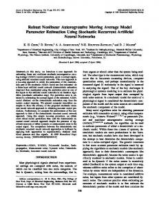
applicability to the real system. The external disturbances are tested by an elastic spring that is physically attached to the index table, as shown in Fig. 10~ The torques induced by the spring have characters of varying disturbances, but they have energies in the low frequencies region. 'Therefore, they can also be attenuated by a high-gain H= controller. Two experiments are repeated with different spring forces. While the index table rotated 0.4 radians, the spring forces varied linearly from 1.5 kgj to 2.5kgj in the first experiment and from 2. 6kgF to 3.5kgj in the second. The final opposed torques caused by the attached spring are 16 kgfcm and 23.5kg~cm in the above two experiments, respectively, The peak torque of the mechanism is around 167.44kgyc~n which is 0.91 (transmission r a t i o ) • 10 (gear r a t i o ) • 18_4(the peak torque of the used motor). The maximum torque by the spring corresponds to 14 % of the peak value of the system and this is a big disturbance in the practical applications of highprecision positioning systems. These torques, in general, degrade the transient responses and give rise to large steady-state errors. Figure 11 shows differences of the positional errors between the cases with two opposed torques and the one without any disturbance. Though the errors by the spring torques increase in the transient stage, the controller still shows good steady-state rsponses despite the exteral spring torque.
Spring
40
~
~
35
Index table
30
i,5 ~ 1050~
1 Conrtoelr 5 outpul Saturatlo n level
0
0.05
01
0.15
ume(sec)
0.2
Fig. 9 The controller output with actuator saturation.
Fig. 10 The index table pulled with a coil spring.
54
Chintae Choi and Jong Shik Kim x 10 ~
,
,
-
,
=
perturbation, noise immunity and disturbance insensitivity which a real-world controller must possess. Superior performance may be obtained if a more accurate position sensor is used.
,
9
:
2.53kg
-
3.56kg
References
2
.
0'2
0.25
ttme(sec)
Fig. 11 The error differences caused by disturbances.
6. Conclusion Friction causes steady-state position errors or tracking lags in servomechanisms. It is necessary to control the postions precisely, without introducing any stable oscillations near the reference position in the existence of friction and disturbances. A design method for a robust motion controller based on high-gain loopshaping synthesis has been presented in this paper. It was applied to an index table requiring high-accuracy position control. The loop-shaping method with H= synthesis provides ease and flexibility in designing a controller which meets the specifications. The high-gain l o o p - s h a p i n g scheme shows that the designed controller is effective in attenuating the friction forces to the desired magnitude. The performance of the controller has been examined through experiments under various load uncertainties and disturbances, including friction. The positional error due to the effect of the friction in the index table was greatly reduced using a suboptimal controller without any feedforward friction compensation. The experimental results demonstrated that the saturation caused by the high-gain contoller does not break nominal and robust stability. The high-gain controller does not completely eliminate the positioning errors caused by friction, but it can reduce the errors to a sufficiently small level. Moreover, it has the robustness to the model
Canudas de Wit et al., 1991, "Adaptive Friction Compensation in Robot Manipulators : Low Velocities," The International Journal o f Robotics Research, Vol. 10, pp. 189--199. Dupont, P. E., 1991, "Avoiding Stick-Slip in Position and Force Control Through Feedback," Proceedings o f the 1991 1EEE Int. Robotics and Automation Conf., Sacramento, pp. 1470-- 1475. Georgiou, T. and Smith, M. , 1987, "Optimal Robustness in the G a p Metric," I E E E Trans. on Automat. Contr. , Vol. 30, pp. 5 5 5 - 5 6 5 . Hsia, T. C., Lasky, T. A. and Guo, Z., 1991, "Robbust Independent Joint Controller Design for Industrial Robot Manipulators," I E E E Trans. Industrial Electronics, Vol. 38. pp. 21 --25. Lee, H. S. and Tomizuka, M., 1994, "Design of Friction-Compensated and Robust Digital Tracking Controllers for High-Accuracy Positioning Systems," Proceedings o f the 1994 Japan-USA Symposium on Flexible Automation. Liang, Y. and Looze, D. P., 1992, "Evaluation of Time-delayed Uncertainty Cancellation Systems," Proceedings o f the A C C pp. 1950 -- 1954. McFarlane, D. C. and Glover, K., 1992, " A Loop Shaping Design Procedure Using Synthesis," I E E E Trans. on Automat. Contr., Vol.37, pp. 759--769. Meyer, D., 1987, Model Reduction via Fractional Representation, Ph.D. thesis, Stanford University. Ohnishi, K., 1987, "A New Servo Method in Mechatronics," Trans. J S E E , Vol. 107-D, pp. 83--86. Rabinowitz, E., 1959, Study of the Stick-Slip Process, Friction and Wear, Ed. Robert Davies, Elsevier Publishing Co.,New York. Ruina, A., 1980, Friction Laws and Instabilities: A Quasistatic Analysis of Some Dry Fric-
Robust High-Gain Loop-Shaping H~ Control of Servomechanisms tional Beha.vior, Ph.D. Dissertation, Brown University. Sampson, J. et al. 1943, "Friction behivior During the Slip Portion of the Stick-Slip," Process. J. of Applied Physics, Vol.14, pp. 689--700. Tung, E. D. et al., 1993, "Low Velocity Friction Compensation for Machine Tool Feed Drves," Proceedings of the A CC, San Francisco, pp. 1932~ 1936. Yang, S. and Tomizuka, M., 1988, "Adaptive
55
Pulse Width Control for Precise Positioning Under the Influence of Stiction and (~7oulomb Friction," ASME, Journal of Dynamic Systems, Measurement, and Control, Vol. 110, pp. 221 --227. Youcef-Toumi, K. and Ito, O., 1990, "A Time Delay Controller for Systems With Unknown Dynamics," ASME, Journal of Dynamic Systems, Measurement, and Control, Vol. ]L12, pp. 133-- 142.