applied sciences Article
Robust Image Watermarking Algorithm Based on ASIFT against Geometric Attacks Chengyou Wang
ID
, Yunpeng Zhang
ID
and Xiao Zhou *
ID
School of Mechanical, Electrical and Information Engineering, Shandong University, Weihai 264209, China;
[email protected] (C.W.);
[email protected] (Y.Z.) * Correspondence:
[email protected]; Tel.: +86-631-568-8338 Received: 14 February 2018; Accepted: 6 March 2018; Published: 9 March 2018
Featured Application: This work embeds the watermark images into host images, realizing the robustness to common attacks and geometric attacks, which can be applied for copyright protection in the field of image transmission, medical, and military research. Abstract: Image processing technology has been developed rapidly in recent years, and altering the content of an image is easy for everyone, but may be illegal for an attacker. Thus, it is urgent and necessary to overcome this problem to protect the integrity and authenticity of images. Watermarking is a powerful technique proposed to solve this problem. This paper introduces a robust image watermarking algorithm working in the wavelet domain, embedding the watermark information into the third level low frequency coefficients after the three-level discrete wavelet transform (DWT) and singular value decomposition (SVD). Additionally, to improve the robustness to geometric attacks, the affine-scale-invariant feature transform (ASIFT) is applied to obtain feature points which are invariant to geometric attacks. Then, features of acquired points between the watermarked image and the received image are used to realize the resynchronization to improve the robustness. Experimental results show that the proposed algorithm achieves great balance between robustness and imperceptibility, and is robust against geometric attacks, JPEG compression, noise addition, cropping, median filters, and so on. Keywords: digital image watermarking; copyright protection; discrete wavelet transform (DWT); affine-scale-invariance feature transform (ASIFT); geometric attacks
1. Introduction With the fast development of information technology, multimedia data has become the most important carrier for information transmission. Digital images, as one of the most important ways for transmitting the information in one or more images, can be easily altered and destroyed by the developed techniques. Thus, to protect the authenticity and integrity of images, schemes applied for copyright protection of images can be essential and meaningful. Based on this purpose, there are mainly two methods proposed to overcome the above problems, which are digital signature [1,2] and digital image watermarking [3–5]. Digital signature is a kind of number string produced by the sender, which can be used as the secret key for both senders and receivers. But it can only detect that images have been tampered or not, and it cannot identify the tampered region location. Thus, watermarking technique is proposed as an effective method to solve the copyright issue of image contents. The categories of digital watermarking algorithms can be divided on the basis of their different robustness and functions: robust watermarking, semi-fragile watermarking, and fragile watermarking. Robust watermarking, as its name implies, should have robustness to all kinds of attacks, which is used for copyright protection. On the converse, fragile watermarking is sensitive
Appl. Sci. 2018, 8, 410; doi:10.3390/app8030410
www.mdpi.com/journal/applsci
Appl. Sci. 2018, 8, 410
2 of 20
to image modification, which includes malicious tampering and un-malicious processing. The last one is semi-fragile watermarking, which can be utilized to make the judgement between malicious tampering and non-malicious modification. Actually, semi-fragile watermarking integrates advantages in robust and fragile watermarking with each other. In addition, semi-fragile watermarking is superior to fragile watermarking when considering the ability of resisting common image operations. In perspective of the domain where the watermark works, watermarking technique can be categorized as spatial or frequency domain [6]. The embedding method of watermark information in spatial domain methods is to directly alter the pixel value of the digital image, and advantages of spatial domain watermarking are easy implementation and low computational complexity. But it has shortcoming that spatial watermarking is not robust to some image processing operations in some degree. Accordingly, the frequency domain methods embed the watermark information by use of modifying frequency coefficients of the original image after transforms. Compared with spatial methods, with the help of mathematical transform, frequency domain watermarking has the better imperceptibility and robustness. There are common mathematical transforms applied in the frequency domain watermarking: discrete wavelet transform (DWT), discrete cosine transform (DCT), singular value decomposition (SVD), and discrete Fourier transform (DFT) [7]. Many typical watermarking schemes are proposed as well as applied in the field of the medical research. Based on Lagrangian support vector regression (LSVR) and lifting wavelet transform (LWT), Mehta et al. [8] proposed an efficient image watermarking scheme, where the Arnold scrambled watermark is embedded into the selected blocks from low frequency sub-band by one level DWT. Makbol et al. [9] presented an innovative image watermarking scheme based on SVD and integer wavelet transform (IWT) to overcome the false positive problem (FPP). In [9], the singular matrix of the watermark is embedded into the singular values of the host image. To obtain the optimized scaling factor, multi-objective ant colony optimization (MOACO) is utilized. Rasti et al. [10] proposed a colour image watermarking algorithm to divide the host image into three channels and calculate the entropy of the patches obtained in the blocks. Certain patches are selected according to the comparison with a predefined threshold for further transforms to embed the watermark. In the aspect of functional magnetic resonance imaging (FMRI) protection, Castiglione et al. [11] introduced a fragile reversible watermarking scheme for achieving authenticity and integrity. In the field of microscopy images protection, Pizzolante et al. [12] introduced a novel watermarking scheme to embed the watermark information into the confocal microscopy image. Traditional watermarking algorithms have robustness to the common attacks, such as noise addition, filter operation, cropping, and so on. However, owing to the unique features of geometric attacks, the watermark synchronization can be destroyed, bringing about the failure in watermark extraction [13]. Thus, it is urgent to propose watermarking algorithms which have resistance to geometric attacks. In recent years, there have been many schemes proposed to solve these problems, which are based on Zernike moments [14], harmonic transform [15], feature points [16], and so on. Due to the fact that SIFT is efficient for the application obtaining the image feature and matching the two images, which makes it more suitable for watermark embedding. However, the scale-invariance feature transform (SIFT) has some advantages: firstly, the significant amount of feature points can be extracted with appropriate parameter settings; secondly, the image feature extracted by SIFT has great uniqueness, which is suitable for accurate matching; finally, SIFT features are invariant to the rotation, scaling, and translations [17], which can be applied as an efficient tool for robust watermarking to acquire the robustness to the geometric attacks. Lee et al. [18] introduced to use local invariant feature for embedding the watermark into the patches of circle shapes generated by SIFT, and proposed an innovative image watermarking scheme. To deal with the watermark synchronization errors, Luo et al. [19] proposed an innovative watermarking scheme based on DFT and SIFT. Based on two techniques, SIFT and DWT, Lyu et al. [20] presented an image watermarking scheme, performing the DWT on the SIFT areas which are selected for watermark embedding. Thorat and Jadhav [21] proposed a watermarking scheme resistant to the geometric attacks based on IWT and SIFT, where SIFT
Appl. Sci. 2018, 8, 410
3 of 20
is utilized on the red channels, and the feature points are extracted. Then, blue and green components are performed by IWT, and low-frequency coefficients can be extracted for watermark embedding. In [22], Pham et al. introduced a robust watermarking algorithm on the basis of SIFT and DCT, where the watermark information is embedded into the specific feature region performed by DCT. In [23], based on SVD and SIFT, Zhang and Tang proposed a robust watermarking scheme for solving the watermark synchronization problem, and SIFT is applied for watermarking resynchronization. To deal with the issue of copyright protection for depth image based rendering (DIBR) 3D images, Nam et al. [24] proposed a SIFT features-based blind watermarking algorithm, where feature points are extracted from different view images. Besides, a watermark pattern selection algorithm based on feature points orientation and spread spectrum technique for watermark embedding are applied in this algorithm. In [25], Kwawamura and Uchida presented a SIFT-based watermarking method, which is evaluated by the information hiding criteria (IHC). The local feature regions around SIFT features are applied for scaling and rotation robustness, and two error correction algorithms are used, which are weighted majority voting (WMV) and low density parity check (LDPC) code to correct the errors of extracted watermarks. As the fast algorithm compared with SIFT, speed up robust feature (SURF) algorithm is applied into watermarking algorithm. Fazli and Moeini [26] presented a geometric-distortion resilient watermarking algorithm, using the fuzzy C-means clustering to process the feature points extracted by SURF, and extracted feature point sets are used to divide the image into triangular patches for watermark embedding. However, the traditional SIFT algorithm can match feature points under the condition of rotation and scaling. As for the tilted image, the feature extracted from the image can be of a small quantity. Concretely, the SIFT algorithm has the feature of scale invariance instead of affine invariance, which can result in the limitation that extraction for an image whose shooting angle changes with a large angle is difficult. In this paper, a novel robust watermarking based on affine-scale-invariance feature transform (ASIFT) [27] in the wavelet domain is presented. Firstly, DWT is performed on the host image for three times, and SVD is operated on the selected low frequency component in horizontal and vertical directions (LL) sub-band. Secondly, the watermark information is embedded into the obtained three-level LL sub-band. The ASIFT points are saved as feature keys for the correction of attacks. Thus, anti-attacks capability can be attained with the help of matching ASIFT feature points in the extraction phase. Finally, experimental results demonstrate that the proposed scheme is imperceptible and resilient to common image processing such as Gaussian noise, salt and pepper noise, speckle noise, median filters, cropping, and so on. Especially for geometric attacks, it has better performance than SIFT-based watermarking. The remainder of this paper is arranged as follows: in Section 2, the related work is reviewed, including the theories of DWT, SVD, and ASIFT; Section 3 introduces the distortion correction by the ASIFT points; Section 4 gives concrete watermark embedding and extraction procedure; comparison with previous schemes in evaluation of robustness and imperceptibility and demonstration of the advantages in the proposed scheme are given in Section 5; conclusions and future work are illustrated finally in Section 6. 2. Related Work 2.1. DWT Theory DWT is the discretization of scaling and translation in basic wavelet theory, which has become a widespread transform in many fields such as signal analysis, image processing, computer recognition, etc. The procedure of DWT decomposition and reconstruction on an image can be illustrated in Figure 1.
Appl. Sci. 2018, 8, 410
4 of 20
Appl. Sci. 2018, 8, x FOR PEER REVIEW
4 of 19
LL2 LL1
HL2
HL1
HL1 LH2 HH2
L
H LH1
Original Image
HH1
One-Level DWT
LH1
HH1
Two-Level DWT
Figure 1. Two-level Two-level discrete discrete wavelet transform (DWT) decomposition and reconstruction of an image.
As can be seen in Figure 1, the original image is firstly performed by one-dimensional DWT in row,row, obtaining the low component (L) and high the direction directionofofevery every obtaining thefrequency low frequency component (L) frequency and high component frequency (H) horizontally. Then, obtained components are performed one-dimensional DWT again in the component (H) horizontally. Then, obtained components areby performed by one-dimensional DWT direction of every column. Finally, low frequency component in horizontal and vertical directions (LL), again in the direction of every column. Finally, low frequency component in horizontal and vertical low frequency horizontal direction and high frequency in high vertical direction the direction high frequency directions (LL),inlow frequency in horizontal direction and frequency in(LH), vertical (LH), in horizontal direction low frequency vertical (HL), and high frequency in horizontal the high frequency in and horizontal directioninand low direction frequency in vertical direction (HL), and high and vertical be obtained. Additionally, first level DWT can bethe noted LL1 , frequency indirections horizontal(HH) and can vertical directions (HH) can bethe obtained. Additionally, firstaslevel LH1 , HL and HH1as . Similarly, the HH LL11.sub-band an example the transform, the second DWT can1 ,be noted LL1, LH1,taking HL1, and Similarly,astaking the LL1for sub-band as an example for level DWT can the be performed with same to getwith the LL , LH , HL , and HH . In the converse, the transform, second level DWT canprocedure be performed same procedure to get the LL 2 , LH 2 , HL 2, 2 2 2 2 the reconstruction of inverse (IDWT) can concluded: performed on transformed and HH2. In the converse, theDWT reconstruction ofbe inverse DWT IDWT (IDWT)iscan be concluded: IDWT is componentson in transformed every columncomponents and in everyinrow next. After two-level IDWT, thenext. reconstructed image performed every column and in every row After two-level can be obtained. IDWT, the reconstructed image can be obtained. 2.2. SVD SVD Theory Theory 2.2. SVD is is a especially in in digital digital image image SVD a common common transform transform applied applied in in image image processing, processing, especially watermarking, which whichisisan anorthogonal orthogonaltransform transform diagonal form of matrix. the matrix. be watermarking, to to getget thethe diagonal form of the To be To more more concrete, suppose is an m × n image matrix with rank r, and Equation (1) can be acquired. concrete, suppose that Ithat is Ian image matrix with rank , and Equation (1) can be acquired. m×n r
Σ Σ 00 U IV = = 0 00 "
#
T U T IV
(1) (1)
,σ, σ≥ } , and σ ≥ 2≥ σ > 0 2. two orthogonal where 1 where UU and and V are V two are orthogonal matrices, Σ matrices, = diag{σ1 ,Σ · ·=· diag{ , σr }, σ and 1 r · · · ≥ σr >1 0. σ1 , · ·r · , σr T I, and SVD of are singular values in the matrix I is represented σ12 ,positive , σr 2 are positive singular values inIthe matrix I T I matrix , and SVD of matrix I by is represented by # ∑ 00 T T I= I =UU VV , , 0 00 "
(2) (2)
" # ∑ 00 where isisthe where thesingular singularvalue valuematrix matrixofofthe theimage, image,which whichcan canbebenoted notedasas SS.. Thus, Thus, the the typical typical 00 00 SVD of the image can be expressed as I = USVTT . (3) (3) I = USV . In practice, SVD becomes the research hotspot because of its three advantages: (i) matrices In practice, SVD becomes the research hotspot because of its three advantages: (i) matrices obtained by SVD are unfixed; (ii) singular values can still remain intact when an image is perturbed; obtained by SVD are unfixed; (ii) singular values can still remain intact when an image is perturbed; and (iii) singular values can represent intrinsic algebraic properties of an image. and (iii) singular values can represent intrinsic algebraic properties of an image. 2.3. ASIFT 2.3. ASIFT In 1999, Lowe [28] introduced a novel algorithm for extracting the local scale-invariant feature points In 1999, Lowe [28] introduced a novel algorithm for extracting theimages, local scale-invariant feature of descriptors, and these descriptors are utilized for matching two related which can be used for points of descriptors, and these descriptors are utilized for matching two related images, which many fields such as image recognition, image registration, image retrieval, 3D reconstruction, and socan on. be used for many fields such as image recognition, image registration, image retrieval, 3D SIFT can deal with the similarity invariance like rotation, scaling, and translation, while some invariance reconstruction, and so on. SIFT can deal with the similarity invariance like rotation, scaling, and translation, while some invariance exploration related to different axis orientation are not concerned.
Appl. Sci. 2018, 8, 410
5 of 20
exploration related to different axis orientation are not concerned. Yu and Morel [29] presented to consider changing the two camera with axis orientation parameters, as known as latitude and longitude angles, for obtaining a set of sample views of the initial images. The core idea of the ASIFT is changing the spatial position of camera optical axis to simulate different viewpoints of images, and then the procedure which is similar to the SIFT algorithm is applied to extract feature points from simulated images. The affine map A can be decomposed uniquely as Equation (4): Appl. Sci. 2018, 8, x FOR PEER REVIEW
"
cos ψ
− sin ψ
#"
t
0
#"
cos φ
− sin φ
5 of 19 #
Yu A and consider changing the two camera with axis orientation parameters, =Morel Hλ R[29] )Tt R2 (φto )= λ , (4) 1 ( ψpresented sin for ψ obtaining cos ψ a set of0sample 1 views sinofφthe initial cos φimages. as known as latitude and longitude angles, The core idea of the ASIFT is changing the spatial position of camera optical axis to simulate images, and then theRprocedure is similar matrices. to the SIFT φ algorithm is where λ >different 0, andviewpoints λt is the of determinant of A. are rotation is a rotation angle 1 and R2which A applied to extract feature points from simulated images. The affine map can be decomposed around image normal by the camera, and ψ is the roll angle around the camera axis. Additionally, Tt is uniquely as Equation (4):
a tilt parameter, which is a diagonal matrix whose first eigenvalue t > 1 and the second one is equal cos ψ − sin ψ t 0 cos φ − sin φ to 1. A = H λ R1 (ψ)Tt R2 (φ ) = λ (4) , ψ 0 1 sin φ cos φ sin The description of affine decomposition inψ thecosgeometric aspect is shown in Figure 2, which demonstrates theλ viewpoints φ and θ,oftheA camera ψ, rotation the zoom parameter and the image R2 are > 0 , and λt isangles the determinant . R1 andspin matrices. rotation where φ is a λ, I. When the camera moveby around the image, and longitude angles will be obtained. is the roll angle around the camera axis. angle aroundstarts imagetonormal the camera, and ψ latitude The plane Additionally, including the and the which optical forms an angle with a fixed tvertical plane, which > 1 and the Tt normal is a tilt parameter, is aaxis diagonal matrix whoseφ first eigenvalue one is equal 1. is named second as longitude. Itstooptical axis then forms an angle θ with the normal to the image plane I, The description of affine decomposition in the there geometric shown in Figure 2, whichwhich are which is named as latitude. Compared with SIFT, are aspect threeisparameters in ASIFT, demonstrates the viewpoints angles φ and θ , the camera spin ψ , the zoom parameter λ , and the the scale, the camera longitude angle, and the camera latitude angle. Besides, rotation and scaling image I . When the camera starts to move around the image, latitude and longitude angles will be parameters are normalized. obtained. The plane including the normal and the optical axis forms an angle φ with a fixed vertical The procedures ASIFTascan be concluded as following with the normal to the plane, which of is named longitude. Its optical generally axis then forms an angle θ steps. image plane I , which is named as latitude. Compared with SIFT, there are three parameters in ASIFT,
Step 1 The original image is performed by simulating all affine distortions resulted from camera which are the scale, the camera longitude angle, and the camera latitude angle. Besides, rotation and optical change frontal position. As is introduced above, these distortions are achieved scalingaxis parameters areanormalized. The procedures of ASIFT be concluded as following steps. the experimental image is by changing the longitudecan φ and latitudegenerally θ gradually. Concretely, performed rotations tilts with the parameter t = 1/|cos θ |, respectively. Step 1 Theby original imageφisand performed by simulating all affineofdistortions resulted from camera optical axis change a frontal position. As is introduced above, these distortions are achievedalgorithm, Step 2 The image stimulated in Step 1 is compared with a similarity invariant matching by changing the longitude φ and latitude θ gradually. Concretely, the experimental where the SIFT is applied. image is performed by rotations φ and tilts with the parameter of t =1/ cos θ , respectively. Step 3 As we all know, SIFT algorithm has its own elimination methods for the wrong points Step 2 The image stimulated in Step 1 is compared with a similarity invariant matching algorithm, matching, which can still result in a certain number of false matches. Owing to the fact that where the SIFT is applied. ASIFT pairsalgorithm of points, matches can be To consider Step 3compares As we all many know, SIFT has many its ownfalse elimination methods foraccumulated. the wrong points can still result in a certain number of false matches. Owing to the fact thatis applied the mostmatching, reliablewhich method, optimized random sampling algorithm (ORSA) [30] ASIFT compares many which pairs of points, many false matches canclassic be accumulated. considerconsensus to filter out false matches, is more robust than the randomTosample the most reliable method, optimized random sampling algorithm (ORSA) [30] is applied to (RANSAC) algorithm. filter out false matches, which is more robust than the classic random sample consensus (RANSAC) algorithm. So far, by only changing the combination of the tilt and rotation parameters, ASIFT can be So far, by only changing the combination the tilt in and rotation ASIFT can be position achieved for full affine invariance simulation. As isofshown Figure 3, parameters, examples of the camera achieved for full affine invariance simulation. As is shown in Figure 3, examples of the camera according to different pairs of φ and θ are denoted. After locating the camera position, simulated affine position according to different pairs of φ and θ are denoted. After locating the camera position, images can be obtained from each position. simulated affine images can be obtained from each position. ψ
λ
θ
I
φ
Figure 2. Geometric interpolation of affine decomposition.
Figure 2. Geometric interpolation of affine decomposition.
Appl. Sci. 2018, 8, 410 Appl. Sci. 2018, 8, x FOR PEER REVIEW Appl. Sci. 2018, 8, x FOR PEER REVIEW
t=2 t=2 t=2 2 t=2 2 t=4 t=4
6 of 20 6 of 19 6 of 19
θ θ
φ φ
x x
y y Figure 3. Observation hemisphere for different camera position. Figure 3. Observation hemisphere for different camera position. Figure 3. Observation hemisphere for different camera position.
3. Resynchronization Algorithm Based on ASIFT 3. Resynchronization Algorithm Based on ASIFT 3. Resynchronization Algorithm Based on ASIFT In general, the image can be attacked by different kinds of factors, such as common image In general, the image can be attacked by different kinds of factors, such as common image In general, image can be attacked by different of factors, can suchresist as common image processing and the geometric attacks. Most robust imagekinds watermarking the common processing and geometric attacks. Most robust image watermarking can resist the common processing watermarking resist which the common processing, processing,and butgeometric geometricattacks. attacksMost can robust changeimage the properties of ancan image, can result in the processing, but geometric attacks can change the properties of an image, which can result in the but geometric attacks can change the properties of an image, which can result in the destruction of destruction of watermark synchronization. To overcome this problem, an ASIFT-based destruction of watermark synchronization. To overcome this problem, an ASIFT-based watermark synchronization. this problem, an ASIFT-based resynchronization algorithm is resynchronization algorithmToisovercome used to extract the feature points as reference points for matching resynchronization algorithm is used to extract the feature points as reference points for matching used to extract between the feature points as reference points for matching establishment between watermarked establishment watermarked and received images. Then, the distortion parameter will be establishment between watermarked and received images. Then, the distortion parameter will be and received images. Then, the distortion will watermark be calculated and inverse can be calculated and inverse processing can beparameter done before extraction to processing get the corrected calculated and inverse processing can be done before watermark extraction to get the corrected done before watermark extraction to get the corrected image. image. image. 3.1. Resynchronization Resynchronization of of Rotation Rotation 3.1. 3.1. Resynchronization of Rotation The definition of rotation is to to rotate The definition of rotation operation operation is rotate the the image image by by aa certain certain angle, angle, which which may may result result The definition of rotation operation is to rotate the image by a certain angle, which may result in the information loss of the original image. After obtaining the feature points of the watermarked in the information loss of the original image. After obtaining the feature points of the watermarked in the information loss of the original image. After obtaining the feature points of the watermarked image and image and attacked attacked image, image, the the resynchronization resynchronization process process of of rotation rotation can can be be expressed expressedas as image and attacked image, the resynchronization process of rotation can be expressed as → → q q i ia ija j 1= 11 q β , β = arccos( iwwwjjjwww× i ××i ja a α a a ), ), k k (5) αr =αr =∑ β , β = arccos ( (5) kβ , kβk = arccos( → rq q (5) k =1 k i j × i j →), w jw × ia ja q1k =1 iw k= × i j w ww a aa a
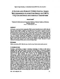
where αr is the correction factor of the rotation, q is the quantity of the matching points between where ααr isisthe thecorrection correctionfactor factorof of the the rotation, rotation, qqisisthe thequantity quantityofofthe thematching matching points points between between where r two images, k is the rank of matchings, and βk is the angle between two images in one matching images, k kis the is the rank of matchings, isangle the angle between two images one matching two images, rank of matchings, andand β k isβthe between two images in oneinmatching of the k k . Moreover, according to the basic mathematic theory of the angle between two which vectors, of thek.rank rank Moreover, according to the basic mathematic theory of the angle between two vectors, is according to the basic mathematic theory of the angle between two vectors, of the rank k .Moreover, → → can be calculated. Based on the coordinates of the matching which is that b = a bθ cos θa ,bβ, the k can that , the canβ calculated. Based on the coordinates of the matching points, a× b = |aaa× βbe be calculated. Based on the coordinates which is that ×||b |=cos a ba,b cos θa ,b , kthe k of the matching → points, the vectors between two matching points can be obtained, which are , vectors in the iw jwthe watermarked the vectors two matching points canpoints be obtained, are iwwhich jw , vectors points, the between vectors between two matching can bewhich obtained, are iin j , vectors in the w w → watermarked in the received Finally, according the β can be obtained image and ia ja ,image vectorsand in thei received image. Finally, the β image. can be obtained to trigonometric j , vectors watermarked image and iaa jaa , vectors in the receivedk image. Finally, the βkk can be obtained function transform. according to trigonometric function transform. according to trigonometric function transform. ◦ Figure Figure 44 shows shows the the matchings matchings between between watermarked watermarked image image and and rotated rotated image image (45 ( 45°).). Figure 4 shows the matchings between watermarked image and rotated image ( 45° ).
45◦°).). Figure Matching Figure4. Matchingpoints pointsbetween betweenimage imageand androtated rotatedimage image(((45 45° ). Figure 4.4.Matching points between image and rotated image
Appl. Sci. 2018, 8, 410 Appl. Sci. 2018, 8, x FOR PEER REVIEW
7 of 20 7 of 19
3.2. Resynchronization Resynchronization of of Translation Translation 3.2. The definition definition of a translation translation operation operation is is to to move move the the pixel pixel points points in in an image from one The coordinate to the other one vertically or horizontally, which can lead to the position the coordinate to the other one vertically or horizontally, which can lead to the errorerror position of theof pixel pixel points. After obtaining the feature the watermarked and received image, points. After obtaining the feature pointspoints of theofwatermarked imageimage and received image, the the resynchronization process of translation be expressed resynchronization process of translation can can be expressed as as ( − x + M , y − y w++NN),), xax
ya ) then yc = ya − yw + N; else yc = ya − yw ; endif; endif;
10 of 20
Appl. Sci. 2018, 8, 410
11 of 20
Algorithm 2. Cont. Variable Declaration: 4Perform DWT on corrected Image to get the LL3 with watermark information [LL1w * , LH1 , HL1 , HH1 ]←DWT (Ic , ‘Haar’); [LL2w * , LH2 , HL2 , HH2 ]←DWT (LL1w * , ‘Haar’); * LH , HL , HH ]←DWT (LL * , ‘Haar’); [LL3w 3 8, x3FOR PEER 3 2w Appl. Sci., 2018, REVIEW 5Perform SVD on the selected sub-band.
11 of 19
T
Vw ←SVD w ); Sw* (Sretrieval. 6Uw Sww Matrix 6Matrix
∗ Sw
∗ Sw *
retrieval.
* Sw =∗Uw ST ww VwT ;
= Uw Sww Vw ;
77Watermark Watermark extraction and decryption. extraction and decryption.
W * =(S * − S) / α ;
∗e We∗ = (Sw − Sw )/α; *
∗ We = (W Arnold We∗ = Arnold e , K);
( We* , K);
Perform threelevel DWT on image
Original image
Watermarked image
Perform threelevel IDWT on LL3
Select LL3 sub-band
Reconstruct the watermarked LL3 sub-band
Perform SVD on the selected sub-band
Dual SVD on watermarked singular matrix
Extract the singular values for embedding
Watermark embedding
Watermark encryption by Arnold transform
Original watermark
Extract the ASIFT points in watermarked image
(a) Attacked image
Extract the ASIFT points in geometrically attacked image
Match the feature points
Correct the distortion of the attacked image
Perform threelevel DWT on corrected image
Extracted watermark
Watermark decryption by Arnold transfom
Extract the watermark
Perform SVD on the selected sub-band
Select watermarked LL3 sub-band
(b) Figure 7. Flowchart of watermark embedding and extraction: (a) watermark embedding; (b) Figure 7. Flowchart of watermark embedding and extraction: (a) watermark embedding; watermark extraction. (b) watermark extraction.
5. Experimental Results and Discussion 5. Experimental Results and Discussion In this section, performances of the ASIFT-based watermarking method are shown and In this section, performances of the ASIFT-based watermarking method are shown and discussed, discussed, which is executed on the 512 × 512 host image and 64 × 64 binary watermark. Additionally, which is executed on the 512 × 512 host image and 64 × 64 binary watermark. Additionally, the scheme the scheme is tested on MATLAB R2015a with an Intel (R) Core (TM), i7-6500U 2.50 GHz CPU, 6 GB is tested on MATLAB R2015a with an Intel (R) Core (TM), i7-6500U 2.50 GHz CPU, 6 GB memory memory computer. To testify the effectiveness of the proposed algorithm, the watermarking scheme computer. To testify the effectiveness of the proposed algorithm, the watermarking scheme is is performed on several images, which are shown in Figure 8. performed on several images, which are shown in Figure 8.
(a)
(b)
(c)
(d)
5. Experimental Results and Discussion In this section, performances of the ASIFT-based watermarking method are shown and discussed, which is executed on the 512 × 512 host image and 64 × 64 binary watermark. Additionally, the scheme is tested on MATLAB R2015a with an Intel (R) Core (TM), i7-6500U 2.50 GHz CPU, 6 GB memory computer. Appl. Sci. 2018, 8, 410 To testify the effectiveness of the proposed algorithm, the watermarking scheme 12 of 20 is performed on several images, which are shown in Figure 8.
(a)
(b)
(c)
(d)
(e)
(f)
(g)
(h)
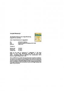
Figure 8. Test images: (a) (a) Airplane; Airplane; (b) Elaine; (c) Lena; (d) (d) Mountain; Mountain; (e) Peppers; (g) Figure 8. Test images: (b) Elaine; (c) Lena; (e) Bank; Bank; (f) (f) Peppers; (g) Milk Milk drop; (h) Gold hill. drop; (h) Gold hill.
5.1. Performance Evaluation The performance of the watermarking algorithm can be evaluated in aspects of imperceptibility and robustness mainly by two indexes: peak signal-to-noise ratio (PSNR) and normalized correlation (NC) coefficients. Generally, a larger PSNR value represents a better visual quality and imperceptibility, and watermarked image whose PSNR is greater than 35 dB can be acceptable. The definition of PSNR for the image with size of M × N can be PSNR = 10lg
2552 2552 MN = 10lg M−1 N −1 (dB), MSE 2 ∑ ∑ [I(i, j) − Iw (i, j)]
(8)
i =0 j =0
where I(i, j) is the pixel coordinate in the original image, and Iw (i, j) is that in the watermarked image. MSE is the short form for mean square error. The robustness of the algorithm can be determined by NC with the value range from 0 to 1, which evaluates the similarity between original watermark and extracted watermark. Similarly, the NC should be 1, but the value greater than 0.7 is acceptable. m
n
∑ ∑ W(i, j) × We (i, j)
NC =
i =1 j =1 m n
,
(9)
∑ ∑ W(i, j) × W(i, j)
i =1 j =1
where W(i, j) and We (i, j) are original watermark and the extracted watermark, respectively. The size of the watermark is m × n. 5.2. Results and Discussion 5.2.1. Performance of Imperceptibility To test the watermark transparency of the watermarked image, the image labelled ‘Elaine’ is used, which contains abundant information, and watermark image of the letter ‘SDU’ (the abbreviation for
size of the watermark is m × n . 5.2. Results and Discussion 5.2.1. Performance of Imperceptibility
Appl. Sci. 2018, 8, 410
13 of 20
To test the watermark transparency of the watermarked image, the image labelled ‘Elaine’ is used, which contains abundant information, and watermark image of the letter ‘SDU’ (the Shandong University) is used to finish isthe experiments. is shown inAs Figure 9, theinwatermarked abbreviation for Shandong University) used to finish theAs experiments. is shown Figure 9, the image can achieve good quality of transparency compared with the original image. watermarked image can achieve good quality of transparency compared with the original image.
(a)
(b)
(c)
(d)
Figure 9. Transparency of the watermarked image: (a) original image; (b) original watermark; (c) Figure 9. Transparency of the watermarked image: (a) original image; (b) original watermark; watermarked image; (d) extracted watermark. (c) watermarked image; (d) extracted watermark.
Additionally, the number number of of ASIFT ASIFT feature feature points points in in test test images imagesare areshown shownin inTable Table1.1. Additionally, the Table 1. Number of affine-scale-invariant feature transform (ASIFT) feature points. Watermarked Images
Number of Points
Airplane Elaine Lena Mountain Bank Peppers Milk drop Gold hill
14,184 9864 10,068 25,833 11,728 8651 6674 17,073
As can be seen in Table 1, the number of points obtained by ASIFT are significant, which has advantages for points matching and distortion correction. 5.2.2. Performance of Robustness To test the robustness of the proposed watermarking scheme thoroughly, common attacks and geometric attacks are performed on the watermarked images. Here, the image labelled ‘Elaine’ is selected as the specific illustration. Figure 10 gives the attacked images and extracted watermarks under different kinds of processes and attacks, which contains JPEG (50 and 70), salt and pepper noise with densities of 0.01 and 0.05, speckle noise with density of 0.01 and 0.1, Gaussian noise with the mean of 0 and the variances of 0.05 and 0.1, median filter with the window sizes of 3 × 3, 4 × 4, and 5 × 5, and center cropping (25%).
geometric attacks are performed on the watermarked images. Here, the image labelled ‘Elaine’ is selected as the specific illustration. Figure 10 gives the attacked images and extracted watermarks under different kinds of processes and attacks, which contains JPEG (50 and 70), salt and pepper noise with densities of 0.01 and 0.05, speckle noise with density of 0.01 and 0.1, Gaussian noise with the of 08, and 4 of × 20 4, Appl.mean Sci. 2018, 410 the variances of 0.05 and 0.1, median filter with the window sizes of 3 × 3,14 and 5 × 5, and center cropping (25%).
(a)
(b)
(c)
(d)
(e)
(f)
(g)
(h)
Figure 10. Cont.
Appl. Sci. 2018, 8, 410 Appl. Sci. 2018, 8, x FOR PEER REVIEW
15 of 20 14 of 19
(i)
(j)
(k)
(l)
(m)
(n)
(o)
(p)
(q)
(r)
(s)
(t)
(u)
(v)
(w)
(x)
Figure 10. 10. Attacked Figure Attacked images images and and extracted extracted watermarks watermarks under under different different kinds kinds of of attacks: attacks: (a) (a) JPEG JPEG (70); (70); (b) extracted watermark from (a); (c) JPEG (50); (d) extracted watermark from (c); (e) salt and pepper (b) extracted watermark from (a); (c) JPEG (50); (d) extracted watermark from (c); (e) salt and pepper noise (0.01); (0.01); (f) (f) watermark extracted from from (e); (e); (g) (g) salt noise watermark extracted salt and and pepper pepper noise noise (0.05); (0.05); (h) (h) extracted extracted watermark watermark from (g); (i) speckle noise (0.01); (j) extracted watermark from (i); (k) speckle noise (0.1); (l) (l) extracted extracted from (g); (i) speckle noise (0.01); (j) extracted watermark from (i); (k) speckle noise (0.1); watermark from from(k); (k);(m) (m)Gaussian Gaussian noise 0.01); extracted watermark (m); (o) Gaussian watermark noise (0, (0, 0.01); (n) (n) extracted watermark fromfrom (m); (o) Gaussian noise noise (0, 0.05); (p) extracted watermark from (o); (q) median filter (3 × 3); (r) extracted watermark from (0, 0.05); (p) extracted watermark from (o); (q) median filter (3 × 3); (r) extracted watermark from (q); (s) median filter (4 × 4); (t) extracted watermark from (s); (u) median filter (5 × 5); (v) extracted (q); (s) median filter (4 × 4); (t) extracted watermark from (s); (u) median filter (5 × 5); (v) extracted watermark from from (u); (u); (w) (w) center center cropping cropping (25%); (25%); (x) (x) extracted extracted watermark watermark from from(w). (w). watermark
In Figure 11, attacked images and extracted watermarks under different kinds of geometric attacks are given, including scaling with parameters of 0.25, 0.5, 0.9, and 1.2, rotation with parameters
Appl. Sci. 2018, 8, 410
16 of 20
In Figure 11, attacked images and extracted watermarks under different kinds of geometric attacks Appl. Sci. 2018, 8, x FOR PEER REVIEW 15 of 19 are given, including scaling with parameters of 0.25, 0.5, 0.9, and 1.2, rotation with parameters of ◦ ◦ ◦ ◦ 5 , 10of, 30 translation parameters of 128 pixels pixels 5° ,, and 10° ,4530,°and 45° , andwith , and translation with parameters of and 128 256 pixels and in 256horizontal pixels in and vertical directions. horizontal and vertical directions.
(a)
(b)
(c)
(d)
(e)
(f)
(g)
(h)
(i)
(j)
(k)
(l)
(m)
(n)
(o)
(p)
Figure 11. Cont.
Appl. Sci. 2018, 8, 410
17 of 20
Appl. Sci. 2018, 8, x FOR PEER REVIEW
(q)
16 of 19
(r)
(s)
(t)
Figure 11. Attacked images and extracted watermarks under geometric attacks: (a) 5° rotation; (b) Figure 11. Attacked images and extracted watermarks under geometric attacks: (a) 5◦ rotation; (b) ° rotation; (d) extracted watermark from (c); (e) 30° rotation; extracted watermark from (a); (c) 10 extracted watermark from (a); (c) 10◦ rotation; (d) extracted watermark from (c); (e) 30◦ rotation; (f) (f) extracted watermark from (e); (g) 45° rotation; (h) extracted watermark from (g); (i) scaling extracted watermark from (e); (g) 45◦ rotation; (h) extracted watermark from (g); (i) scaling (0.25); (0.25); (j) extracted watermark from (i); (k) scaling (0.5); (l) extracted watermark from (k); (m) scaling (j) extracted from (i);from (k) (m); scaling (0.5); (l) extracted watermark from (k); (m) (0.9); (n) watermark extracted watermark (o) scaling (1.2); (p) extracted watermark from (o); (q)scaling vertical (0.9); (n) extracted (m); (o)watermark scaling (1.2); watermark from (q) vertical translationwatermark (256 pixels);from (r) extracted from(p) (q);extracted (s) horizontal translation (256(o); pixels); (t) translation (256 pixels); from (r) extracted watermark from (q); (s) horizontal translation (256 pixels); (t) extracted watermark (s). extracted watermark from (s). Tables 2 and 3 give the robustness performance of the proposed scheme on different images, and the image labelled ‘Elaine’ with less points as well as the image labelled ‘Gold hill’ with more points Tables 2 and 3 give the robustness performance of the proposed scheme on different images, are selected as the representatives.
and the image labelled ‘Elaine’ with less points as well as the image labelled ‘Gold hill’ with more points are selected as theTable representatives. 2. Robustness of the proposed algorithm on image Elaine. Common Attacks NC Geometric Attacks NC Table 2. Robustness of the proposed algorithm on image Elaine. No attacks 0.9980 Scaling 0.25 0.9904 JPEG (50) 0.9966 Scaling 0.5 0.9969 Common Attacks NC Geometric Attacks NC JPEG (70) 0.9971 Scaling 0.9 0.9961 No attacks 0.9980 0.25 Median filter (3 × 3) 0.9939 ScalingScaling 1.2 0.9911 0.9904 JPEG (50) 0.9966 Scaling 0.5 Median filter (4 × 4) 0.9868 Rotation 2° 0.9704 0.9969 JPEG (70) 0.9971 Scaling 0.9 0.9961 Rotation 5° 0.9858 Median filter (5 × 5) 0.9542 Median filter (3 × 3) 0.9939 Scaling 1.2 0.9911 Rotation 10° Gaussian noise (0, 0.05) 0.9293 0.9784 Median filter (4 × 4) 0.9868 Rotation 2◦ 0.9704 30° RotationRotation Gaussian 0.8315 0.9685 0.9542 Median filter (5 × 5)noise (0, 0.1) 0.9858 5◦ 45° RotationRotation Speckle noise (0.01) 0.9873 0.9608 0.9784 Gaussian noise (0, 0.05) 0.9293 10◦ ◦ Speckle 0.9254 Horizontally translation (25630pixels) 0.9974 0.9685 Gaussian noise (0, 0.1)noise (0.1) 0.8315 Rotation and(0.01) pepper noise (0.01) 0.9873 0.9856 Vertically translation (256 pixels) 0.9974 0.9608 SpeckleSalt noise Rotation 45◦ Horizontally translation (256 pixels) Speckle noise Salt and(0.1) pepper noise (0.05) 0.9254 0.9452 Horizontally translation (128 pixels) 0.9978 0.9974 Salt and pepper noisecropping (0.01) (25%) 0.9856 Vertically translation (256 pixels) Center 0.8461 Vertically translation (128 pixels) 0.9978 0.9974 Salt and pepper noise (0.05) 0.9452 Horizontally translation (128 pixels) 0.9978 Center cropping (25%) 0.8461 Vertically translation (128 pixels) 0.9978 As can be seen in Table 2, the robustness performance of the proposed algorithm is given on the
host image ‘Elaine’ and the watermark image ‘SDU’. The PSNR value of the proposed method is 52.57 dB, can which the good transparency of the watermarked As beillustrates seen in Table 2, the robustness performance ofimage. the proposed algorithm is given on
the host image ‘Elaine’ and the watermark image ‘SDU’. The PSNR value of the proposed method is Table 3. Robustness of the proposed algorithm on image Gold hill. 52.57 dB, which illustrates the good transparency of the watermarked image. Common Attacks No attacks JPEG (50) JPEG (70) Median filter (3 × 3) Median filter (4 × 4) Median filter (5 × 5)
NC 0.9978 0.9964 0.9973 0.9955 0.9885 0.9896
Geometric Attacks Scaling 0.25 Scaling 0.5 Scaling 0.9 Scaling 1.2 Rotation 2° Rotation 5°
NC 0.9910 0.9972 0.9968 0.9943 0.9802 0.9867
Appl. Sci. 2018, 8, 410
18 of 20
Table 3. Robustness of the proposed algorithm on image Gold hill. Common Attacks
NC
Geometric Attacks
NC
No attacks JPEG (50) JPEG (70) Median filter (3 × 3) Median filter (4 × 4) Median filter (5 × 5) Gaussian noise (0, 0.05) Gaussian noise (0, 0.1) Speckle noise (0.01) Speckle noise (0.1) Salt and pepper noise (0.01) Salt and pepper noise (0.05) Center cropping (25%)
0.9978 0.9964 0.9973 0.9955 0.9885 0.9896 0.9253 0.8492 0.9921 0.9670 0.9835 0.9507 0.8597
Scaling 0.25 Scaling 0.5 Scaling 0.9 Scaling 1.2 Rotation 2◦ Rotation 5◦ Rotation 10◦ Rotation 30◦ Rotation 45◦ Horizontally translation (256 pixels) Vertically translation (256 pixels) Horizontally translation (128 pixels) Vertically translation (128 pixels)
0.9910 0.9972 0.9968 0.9943 0.9802 0.9867 0.9909 0.9893 0.9909 0.9973 0.9973 0.9976 0.9976
In Table 3 the robustness performance of the proposed algorithm is given on the host image ‘Gold hill’ and the watermark image ‘SDU’. The PSNR value is 51.01 dB. In general, the image labelled ‘Gold hill’ has more points than the image labelled ‘Elaine’. Thus, the robustness to geometric attacks on ‘Gold hill’ is a little better than that on ‘Elaine’. 5.3. Performance Comparison To further prove the performance of the proposed algorithm, the experiments were executed on comparing the proposed method with previous scheme [31], which applied the SIFT algorithm for distortion correction. The NC results are shown in Table 4. It can be concluded that, the ASIFT-based watermarking scheme has better robustness in scaling, translation, and rotation in small angles than the watermarking algorithm based on SIFT. Table 4. Performance comparisons with previous algorithms. Attacks
SIFT [31]
ASIFT
Scaling 0.25 Scaling 0.5 Scaling 0.9 Scaling 1.2 Rotation 2◦ Rotation 5◦ Rotation 10◦ Rotation 30◦ Rotation 45◦ Horizontally translation (256 pixels) Vertically translation (256 pixels) Horizontally translation (128 pixels) Vertically translation (128 pixels)
0.9832 0.9889 0.9901 0.9871 0.9887 0.9918 0.9954 0.9954 0.9941 0.9847 0.9847 0.9853 0.9853
0.9904 0.9969 0.9961 0.9911 0.9704 0.9542 0.9784 0.9685 0.9608 0.9974 0.9974 0.9978 0.9978
6. Conclusions With the rapid development of image processing technology, altering the content of an image is easy for everyone, but may be illegal for an attacker. It is urgent and necessary to overcome this problem, to protect the integrity and authenticity of images. Watermarking is a powerful technique proposed to solve this problem. In this paper, an ASIFT-based robust watermarking algorithm is proposed to solve the geometric attacks in copyright protection issues. In the proposed algorithm, the watermark information is inserted into the low frequency sub-band after DWT three times, where the SVD is performed again for watermark embedding. While in the extraction process, to improve
Appl. Sci. 2018, 8, 410
19 of 20
the robustness to geometric attacks, ASIFT is applied to obtain feature points which are invariant to geometric attacks. Then, features of acquired points between the watermarked image and received image are used to realize the resynchronization to improve the robustness. Experimental results show that the proposed algorithm achieves great balance between robustness and imperceptibility, and is robust against geometric attacks, JPEG compression, noise addition, copping, filter operation, and so on. In the future work, SIFT correction can be applied to video watermarking for rotation resistance. Acknowledgments: This work was supported by the National Natural Science Foundation of China (No. 61702303, No. 61201371); the Natural Science Foundation of Shandong Province, China (No. ZR2017MF020, No. ZR2015PF004); and the Research Award Fund for Outstanding Young and Middle-Aged Scientists of Shandong Province, China (No. BS2013DX022). Author Contributions: Chengyou Wang and Yunpeng Zhang conceived the algorithm and designed the experiments; Yunpeng Zhang performed the experiments; Chengyou Wang and Xiao Zhou analyzed the results; Yunpeng Zhang drafted the manuscript; Chengyou Wang, Yunpeng Zhang and Xiao Zhou revised the manuscript. All authors read and approved the final manuscript. Conflicts of Interest: The authors declare no conflict of interest.
References 1. 2. 3. 4.
5. 6.
7. 8. 9.
10.
11.
12.
13. 14.
Shiva, M.G.; D’Souza, R.J.; Varaprasad, P. Digital signature-based secure node disjoint multipath routing protocol for wireless sensor networks. IEEE Sens. J. 2012, 12, 2941–2949. Chain, K.; Kuo, W.C. A new digital signature scheme based on chaotic maps. Nonlinear Dyn. 2013, 74, 1003–1012. [CrossRef] Asifullah, K.; Ayesha, S.; Summuyya, M.; Sana, A.M. A recent survey of reversible watermarking techniques. Inf. Sci. 2014, 279, 251–272. Ritu, J.; Munesh, C.T.; Shailesh, T. Digital audio watermarking: A survey. In Proceedings of the International Conference on Computer, Communication and Computational Sciences, Ajmer, India, 12–13 August 2016; Volume 554, pp. 433–443. Asikuzzaman, M.; Mark, R.P. An overview of digital video watermarking. IEEE Trans. Circuits Syst. Video Technol. 2017. [CrossRef] Su, Q.T.; Wang, G.; Lv, G.H.; Zhang, X.F.; Deng, G.L.; Chen, B.J. A novel blind color image watermarking based on contourlet transform and Hessenberg decomposition. Multimed. Tools Appl. 2017, 76, 8781–8801. [CrossRef] Singh, D.; Singh, S.K. DWT-SVD and DCT based robust and blind watermarking scheme for copyright protection. Multimed. Tools Appl. 2017, 76, 13001–13024. [CrossRef] Mehta, R.; Rajpal, N.; Vishwakarma, V.P. A robust and efficient image watermarking scheme based on Lagrangian SVR and lifting wavelet transform. Int. J. Mach. Learn. Cybern. 2017, 8, 379–395. [CrossRef] Makbol, N.M.; Khoo, B.E.; Rassem, T.H.; Loukhaoukha, K. A new reliable optimized image watermarking scheme based on the integer wavelet transform and singular value decomposition for copyright protection. Inf. Sci. 2017, 417, 381–400. [CrossRef] Rasti, P.; Anbarjafari, G.; Demirel, H. Colour image watermarking based on wavelet and QR decomposition. In Proceedings of the 25th Signal Processing and Communications Applications Conference, Antalya, Turkey, 15–18 May 2017. Castiglione, A.; De Santis, A.; Pizzolante, R.; Castiglione, A.; Loia, V.; Palmieri, F. On the protection of fMRI images in multi-domain environments. In Proceedings of the 29th IEEE International Conference on Advanced Information Networking and Applications, Gwangju, Korea, 25–27 March 2015; pp. 476–481. Pizzolante, R.; Castiglione, A.; Carpentieri, B.; De Santis, A.; Castiglione, A. Protection of microscopy images through digital watermarking techniques. In Proceedings of the International Conference on Intelligent Networking and Collaborative Systems, Salerno, Italy, 10–12 September 2014; pp. 65–72. Fazli, S.; Moeini, M. A robust image watermarking method based on DWT, DCT, and SVD using a new technique for correction of main geometric attacks. Optik 2016, 127, 964–972. [CrossRef] Lutovac, B.; Dakovi´c, M.; Stankovi´c, S.; Orovi´c, I. An algorithm for robust image watermarking based on the DCT and Zernike moments. Multimed. Tools Appl. 2017, 76, 23333–23352. [CrossRef]
Appl. Sci. 2018, 8, 410
15.
16. 17.
18. 19. 20. 21. 22.
23.
24. 25.
26. 27. 28. 29. 30. 31.
20 of 20
Yang, H.Y.; Wang, X.Y.; Niu, P.P.; Wang, A.L. Robust color image watermarking using geometric invariant quaternion polar harmonic transform. ACM Trans. Multimed. Comput. Commun. Appl. 2015, 11, 1–26. [CrossRef] Zhang, Y.P.; Wang, C.Y.; Wang, X.L.; Wang, M. Feature-based image watermarking algorithm using SVD and APBT for copyright protection. Future Internet 2017, 9, 13. [CrossRef] Ye, X.Y.; Chen, X.T.; Deng, M.; Wang, Y.L. A SIFT-based DWT-SVD blind watermark method against geometrical attacks. In Proceedings of the 7th International Congress on Image and Signal Processing, Dalian, China, 14–16 October 2014; pp. 323–329. Lee, H.; Kim, H.; Lee, H. Robust image watermarking using local invariant features. Opt. Eng. 2006, 45, 535–545. Luo, H.J.; Sun, X.M.; Yang, H.F.; Xia, Z.H. A robust image watermarking based on image restoration using SIFT. Radio Eng. 2011, 20, 525–532. Lyu, W.L.; Chang, C.C.; Nguyen, T.S.; Lin, C.C. Image watermarking scheme based on scale-invariant feature transform. KSII Trans. Internet Inf. Syst. 2014, 8, 3591–3606. Thorat, C.G.; Jadhav, B.D. A blind digital watermark technique for color image based on integer wavelet transform and SIFT. Procedia Comput. Sci. 2010, 2, 236–241. [CrossRef] Pham, V.Q.; Miyaki, T.; Yamasaki, T.; Aizawa, K. Geometrically invariant object-based watermarking using SIFT feature. In Proceedings of the 14th IEEE International Conference on Image Processing, San Antonio, TX, USA, 16–19 September 2007; Volume 5, pp. 473–476. Zhang, L.; Tang, B. A combination of feature-points-based and SVD-based image watermarking algorithm. In Proceedings of the International Conference on Industrial Control and Electronics Engineering, Xi’an, China, 23–25 August 2012; pp. 1092–1095. Nam, S.H.; Kim, W.H.; Mun, S.M.; Hou, J.U.; Choi, S.; Lee, H.K. A SIFT features based blind watermarking for DIBR 3D images. Multimed. Tools Appl. 2017, 1–40. [CrossRef] Kawamura, M.; Uchida, K. SIFT feature-based watermarking method aimed at achieving IHC ver. 5. In Proceedings of the 13th International Conference on Intelligent Information Hiding and Multimedia Signal Processing, Matsue, Shimane, Japan, 12–15 August 2017; pp. 381–389. Fazli, S.; Moeini, M. A rough geometric-distortion resilient watermarking algorithm using fuzzy C-means clustering of SURF points. Int. J. Eng. Technol. Sci. 2015, 3, 210–220. Yu, G.S.; Morel, J.M. ASIFT: An algorithm for fully affine invariant comparison. Image Process. On Line 2011, 1, 11–38. [CrossRef] Lowe, D.G. Object recognition from local scale-invariant features. In Proceedings of the 7th IEEE International Conference on Computer Vision, Kerkyra, Corfu, Greece, 20–27 September 1999; Volume 2, pp. 1150–1157. Morel, J.M.; Yu, G.S. ASIFT: A new framework for fully affine invariant image comparison. SIAM J. Imaging Sci. 2009, 2, 438–469. [CrossRef] Moisan, L.; Stival, B. A probabilistic criterion to detect rigid point matches between two images and estimate the fundamental matrix. Int. J. Comput. Vis. 2004, 57, 201–218. [CrossRef] Zhang, Y.P.; Wang, C.Y.; Zhou, X. RST resilient watermarking scheme based on DWT-SVD and scale-invariant feature transform. Algorithms 2017, 10, 41. [CrossRef] © 2018 by the authors. Licensee MDPI, Basel, Switzerland. This article is an open access article distributed under the terms and conditions of the Creative Commons Attribution (CC BY) license (http://creativecommons.org/licenses/by/4.0/).