This is a repository copy of Robust iterative feedback tuning control of a compliant rehabilitation robot for repetitive ankle training. White Rose Research Online URL for this paper: http://eprints.whiterose.ac.uk/125848/ Version: Accepted Version Article: Meng, W, Xie, SQ, Liu, Q et al. (2 more authors) (2017) Robust iterative feedback tuning control of a compliant rehabilitation robot for repetitive ankle training. IEEE/ASME Transactions on Mechatronics, 22 (1). pp. 173-184. ISSN 1083-4435 https://doi.org/10.1109/TMECH.2016.2618771
(c) 2017 IEEE. Personal use of this material is permitted. Permission from IEEE must be obtained for all other uses, in any current or future media, including reprinting/republishing this material for advertising or promotional purposes, creating new collective works, for resale or redistribution to servers or lists, or reuse of any copyrighted component of this work in other works
Reuse Unless indicated otherwise, fulltext items are protected by copyright with all rights reserved. The copyright exception in section 29 of the Copyright, Designs and Patents Act 1988 allows the making of a single copy solely for the purpose of non-commercial research or private study within the limits of fair dealing. The publisher or other rights-holder may allow further reproduction and re-use of this version - refer to the White Rose Research Online record for this item. Where records identify the publisher as the copyright holder, users can verify any specific terms of use on the publisher’s website. Takedown If you consider content in White Rose Research Online to be in breach of UK law, please notify us by emailing
[email protected] including the URL of the record and the reason for the withdrawal request.
[email protected] https://eprints.whiterose.ac.uk/
> REPLACE THIS LINE WITH YOUR PAPER IDENTIFICATION NUMBER (DOUBLE-CLICK HERE TO EDIT)
REPLACE THIS LINE WITH YOUR PAPER IDENTIFICATION NUMBER (DOUBLE-CLICK HERE TO EDIT) < performance [14]. As mentioned above, the device utilises a novel type of pneumatic powered actuator, and the speed and range of patient’s recovery can lead to significant changes to the model of the rehabilitation robot, all of which indicate that a model-based method is not suitable, and a robust model-free method will be a prime candidate. Iterative feedback tuning (IFT) is a model-free data-driven learning method [15]. Further, IFT is very much suitable for repeated rehabilitation trajectories due to the requirement of specially designed experiments. On the other hand, IFT as compared to traditional control systems has the advantage where it can be auto-tuned only depending on the input and output data collected from the experiments, which does not contain any model information about the controlled plant. This allows the system to be highly robust to uncertainties [16, 17]. There have been some interesting cases for the application of IFT in various industrial fields, such as DC-servo control, robotic arm and mass spring system, etc., due to its superior model-free automatic tuning capacity [17-21]. However, the use of iterative feedback learning control in rehabilitation has not been well-explored [22]. The most prominent case for application of ILC on rehabilitation devices is to control the value of functional electrical stimulation (FES) for upper limb therapy as presented in [23, 24], in which ILC was worked as a kind of “high-level” controller to adjust the amount of FES for upper limb. Few other previous researches invoke the use of ILC on rehabilitation platforms. In [25], a form of iterative learning control was implemented on the Lokomat robot to synchronise the leg and treadmill movements. A PID plus iterative learning-based feed forward controller was proposed on an upper extremity therapy robot for repetitive task training [13]. As for the iterative feedback tuning technique, there is no reported literature on the specific combination of IFT and rehabilitation devices, also no IFT instances on PMAs-driven equipment. By transferring the idea of IFT to rehabilitation robotics, we believe that the robot controller can also improve its performance from repetitive trials. In rehabilitation environment, there is often an external disturbance from the patient during the training and this will lead to significant changes to the control parameters of the robot used. Therefore, robust control system implementation is one major difficult task and it is even harder to enhance the robustness during long time repetitive training. Hussain et al. utilised a charting-free robust variable structure controller for the designed robotic gait orthosis [26]. Xu et al. proposed an evolutionary dynamic recurrent fuzzy neural network to provide more robustness for upper limb rehabilitation [27]. One shortcoming of these methods if applying them to our system is that the dynamic modelling of pneumatic muscles and robot behaviour would bring heavy computation burden to the control system, and it is also difficult to model the patient’s arbitrary activities. One advantage of IFT technique is its ability to learn from repeating scenarios and optimise the controller parameters without knowledge of the actual system, which guarantees the inherent robustness of such a method [15, 17, 28]. To obtain a more robust control system, the design criterion or objective function of IFT must be taken into
2
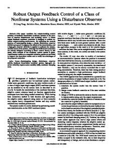
account. Introduce a plenty function to the input signal for certain restrictions is a typical approach to increase the system robustness, such as the studies in [17] and [28]. However, in rehabilitation scenarios the robot system will have various desired and actual output, error, as well as control input signal, especially when treat patients in different recovery stages and with different active intentions. The robustness problem of IFT controller should be investigated further. We will propose a novel robust IFT controller to make the controller system agnostic and meaningful across different situations. According to the authors’ best knowledge, IFT control of a rehabilitation robot has not been reported in the literature. In this paper, a normalised IFT (NIFT) technique is applied for the repetitive training control of a flexible ankle rehabilitation robot actuated by PMAs. A novel multiple degrees-of-freedom (DOFs) IFT method with normalised criterion is proposed to improve the robustness under varying training conditions. The rest of this paper is organised as follows: Section II demonstrates the details of the compliant ankle rehabilitation robot. In Section III, methodology of the proposed multiple DOFs normalised IFT method is presented. Experiments including comparison test and human participants test were conducted in Section IV, followed by the discussion in Section V. The conclusion is drawn in Section VI. II. COMPLIANT ANKLE REHABILITATION ROBOT We had developed a novel ankle rehabilitation platform, with the new prototype shown in Fig. 1. This robot is actuated by four parallel links to realise three rotational DOFs of the end-effector for ankle dorsiflexion/plantarflexion, inversion/ eversion, and adduction/abduction, respectively. Each joint is actuated using a pneumatic muscle actuator from FESTO™ (FESTO DMSP-20-400N) in order to guarantee the intrinsic compliance of the robot during operation. It has a stroke length of 100mm, a maximum force of over 5000N, and an internal diameter of 20mm. Each pneumatic muscle actuator is controlled by a proportional pressure regulator. The endeffector is a three-link serial manipulator with three rotational DOFs, in which three magnetic rotary encoders are installed to provide measurements of angular positions of the robot in Euler X, Y and Z axes. Additionally, a six-axis load cell is mounted between the robot end-effector and a human foot to measure the human robot interaction force and torque. For the control system hardware, a National Instruments embedded controller (NI Compact RIO-9022) is adopted for real-time control. The control system now runs on a host PC using LabVIEW™, with the communication between the PC and the embedded solution performed using the TCP/IP protocol. In order to control the robot end-effector to track a predefined trajectory for ankle movement training, the robot kinematic model must be studied. Inverse kinematics of a robot describes the translation of the end-effector orientation to the length of the active links, which is essential for any form of robot control. Fig. 2 presents the robotic kinematic geometry of the developed parallel ankle rehabilitation robot. The fixed and the moving one is coordinate frame is denoted by
> REPLACE THIS LINE WITH YOUR PAPER IDENTIFICATION NUMBER (DOUBLE-CLICK HERE TO EDIT) < denoted by . Connection points on the fixed and moving platforms are denoted by and , respectively, and their position vectors and are defined in (1) as well as the position vector , where is the centre distance between the fixed platform and the moving end-effector. A table of all variables can be found in the Nomenclature. X
S
E )
) Y
Y P
X
PMA
E
L F
S
P
C
III. MULTI-DOF NIFT CONTROL SYSTEM As the ankle rehabilitation robot has multiple actuators to be controlled, the implementation of multiple instances of the IFT technique is explored. The base control structure is presented in Fig. 3, where inverse kinematics is used to obtain the joint space trajectory for each actuator. The reference and actual position of each link are evaluated from the desired and the measured end-effector orientation orientation respectively by using inverse kinematics. These actuators are then controlled individually using a PID controller with the parameter vector being tuned by the IFT technique. In the control structure, the same set of starting parameters of was applied to all four controllers. The outer control loop regulates the angular position, and each of the inner control loops regulates air pressure of each PMA. The PMA model is used to convert the control signal into air pressure for each proportional regulator.
l1
A C
Fig. 1. Prototype of the compliant parallel ankle rehabilitation robot. F
P4 f ( x f , y f )
z
Of
IFT T
P3 f ( x f , y f )
l2
Of
P1 f ( x f , y f )
A C
l3
l4
P ( xm , ym ) m 4
z Om
P
p1
S
P
PID
u2
IFT T
P2 f ( x f , y f ) K
Om
PMA M
I
PMA M
P
p2
S P
l2
u3
PID
P ( xm , ym )
IFT T
XYZ
PMA
PMA M
P
p3
E E O
S
l3
m 3
A C
PMA
d , XYZ
y
l1
u1
PID
x
pif
3
P
PMA
x
O
pim
P1m ( xm , ym )
y
A C
P2m ( xm , ym )
E
IFT T
As shown in Fig. 2, by defining the connection points and a rotating coordinate system, the vector of each active link can be calculated. The position vector of the link is described in (2), where the rotational transformation matrix of the endeffector with respect to the fixed platform is denoted by matrix using a sequence of . The link length is expressed by in (3), where is the function, is the function, and the subscripts represent corresponding Euler angles, for example, .
u4
PMA M
p4
P
S
l4
Fig. 2. Kinematic structure of the parallel ankle rehabilitation robot.
PID
(1) (2) (3) (4)
P
PMA
v(t )
KP
r (t )
u (t )
KI s Cr ( )
KD s
G
PMA
y (t )
KP KI s
Cy ( )
KD s
Fig. 3. Control system of the ankle rehabilitation robot. (a) Structure of the multiple DOFs IFT. (b) Diagram of the controller for each PMA.
A. IFT Tuning of PID parameters on PMA Each pneumatic muscle is controlled individually using a standard PID controller, and for IFT tuned PID controller, as suggested by [29], it must be considered as a 2-DOF controller with common parameters. A block diagram of the controller in is shown in Fig. 3 (b), where the form sharing the same parameters both together and constitute the PID controller. The PMA is considered as an unknown system , and the reference input, the controller output, the response output, the unmeasurable disturbance. The parameters for and are collected and optimised in a . vector of controller parameters: Considering the controller shown in Fig. 3 (b), the system
> REPLACE THIS LINE WITH YOUR PAPER IDENTIFICATION NUMBER (DOUBLE-CLICK HERE TO EDIT) < response can be expressed by using (5).
(11)
(5) The objective for an iterative learning control is to generate a sequence of appropriate control inputs to drive the system output approaches the reference trajectory , for iteration . Each iteration of control input generation should take the output closer to the reference trajectory by the IFT algorithm. Details of the general IFT algorithm can be found in [29]. The used design criterion takes into account both the error response as well as the controller input magnitude. is a predetermined weighting factor between the two cost function component variables, and is usually obtained empirically through trial and error. More discussion on the selection of will be presented in next section.
(6)
Here is a vector of process parameters to be optimised, is the error between the actual output and the desired output signal (
, so
and
(12) and As parameter vector controller is:
are PID controllers with the same , transfer function of PID . For discrete system: (13)
(14)
and with respect to each The partial derivative of controller parameter can be written as:
), and
is the total number of samples collected. The optimised controller parameter vector is defined as shown in (7). arg min (7) The partial derivative of controller parameters is:
4
(15)
with respect to the
(8)
(16)
(9) The partial derivatives
and
can be obtained by
performing actual experiments on the system. Normally, three experiments are required to complete each iteration of the optimisation process. First, a reference signal is applied to the closed-loop system as input and the output data is recorded. Second, the output from the first experiment is re-applied to the system as the reference input. A third experiment is performed where the first test signal is used as the reference [30]. The outputs from the second and the third experiment will be utilised to calculate the gradient of the controller parameters. As illustrated by Eq. (10), this is done to ensure that the data from the second and third experiments are independent of each other in order to reduce bias. (10) Here are disturbances come from different experiments and thus are mutually independent. Then, the unbiased estimate of the partial derivatives can be achieved by:
The estimated gradient of the design criterion for the iteration based entirely on experimental data can be constructed from the estimated partial derivatives: (17) is calculated The next iterate by using the Gauss-Newton optimisation algorithm, based on . the gradient of and previous (18) where is a positive value to indicate the step size. is a matrix to imply the optimised search direction, here a positive Gauss-Newton approximation to the Hessian matrix is applied: (19)
> REPLACE THIS LINE WITH YOUR PAPER IDENTIFICATION NUMBER (DOUBLE-CLICK HERE TO EDIT) < It is essential to select a proper step size for IFT to maintain the balance between convergence and stability of the IFT algorithm. Firstly, the step size must obey some constraints so that the design criterion can converge to a local minimum soon [29]. Secondly, the step size must be chosen to make the closed-loop system maintain stable [31]. Usually a step size with constraint will be applied [28]. As suggested by [21], if the step size is set small enough and the dataset is relatively large, the convergence of IFT algorithm can be ensured. In practice, the step size for each controller will need to be defined empirically, often through trial and error. B. Normalised design criterion for IFT The performance of the IFT process can be influenced by several factors. In order to determine an optimal value of , it is important to consider the relative magnitudes of each variable in the design criterion . Different systems will have variable desired and actual output, error, as well as control and , signal. When considering the combination of the value obtained from trial and error will contain the properties specific to the system being tuned. There needs to be a method to remove the system properties from , as in making weighting factor normalised so that it can be comparable and agnostic across different systems [32]. Eq. (20) proposes a normalised design criterion, where a normalising factor is introduced, and replaces to be the weighting factor that remains meaningful. (20) where the normalising coefficient
is determined by:
(21)
and are the maximum and where minimum value in the desired output and the control signal, respectively. As all four values are only determined at the end of each optimisation iteration, all data points are taken into account so the normalisation process is a fair representation of the current iteration. The normalised design criterion for IFT stays meaningful across different ensures that the value of tuning iterations [30]. With normalised design criterion, it values that represent becomes possible to determine sets of the optimal range for IFT tuning for various situations. The estimated gradient of the normalised design criterion iteration can be then constructed by using (22) for the becomes (23): and the Gauss-Newton Hessian matrix (22)
5
Therefore, the key to the iterative feedback tuning method is the iterative computation of results. As long as and
are obtained, the
from experiment
and
and the gradients
and
can be estimated
by the introduction of and . Then the controller parameters can be updated accordingly: (24) To summarise, the procedure of normalised IFT algorithm is: (i) Choose the starting controller parameters and select the ; (ii) Perform three normalized design criterion experiments ; (iii) Estimate partial derivatives criterion
and
; (iv) Evaluate the gradient of ; (v) Obtain the new
and Hessian matrix
controller parameters ; and (vi) Evaluate the criterion and check the performance, if stop criterion reached go to (vii) finish, otherwise go to (ii) for next iteration loop. C. Convergence and robustness aspects Convergence property of standard IFT has been analysed in [29] and [16], here we study the normalised IFT method. The convergence conditions as stated in [33] are: (1) the estimated gradient of the objective function is unbiased; (2) the step size sequence converges to zero but not too fast. For Condition (1), the unbiased gradient estimate is the key property of IFT. In this study we use three specially designed experiments to generate the gradient based descent direction, which can obtain unbiased gradient estimates without the use of parametric models [28]. From Eq. (8)-(10), the following expression of derivatives
and
can be derived: (25) (26)
As and are mutually independent bounded stochastic noises of the same system, the equations (11) and (12) are the unbiased estimate of
and
. Thus, the estimated
gradient of the normalised objective function is also unbiased, as illustrated by Eq. (22). For Condition (2), the usual conditions for convergence can be guaranteed for the choice of : (27)
(23)
This condition is fulfilled e.g. by having , where is a certain positive constant. However, this requirement may that have a slow convergence rate. Though the matrix determines the update direction does not influence the IFT’s convergence ability, as stated in [17], Gauss-Newton direction
> REPLACE THIS LINE WITH YOUR PAPER IDENTIFICATION NUMBER (DOUBLE-CLICK HERE TO EDIT)
REPLACE THIS LINE WITH YOUR PAPER IDENTIFICATION NUMBER (DOUBLE-CLICK HERE TO EDIT)
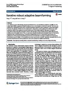
REPLACE THIS LINE WITH YOUR PAPER IDENTIFICATION NUMBER (DOUBLE-CLICK HERE TO EDIT) < error for T2 and T3 was higher than that of T1, due to the influence of human effects, but the control performance at the end of tuning were all satisfactory. The controller parameters in Fig. 7 can be examined to see the effect of NIFT tuning process. The value of in T2 and T3 was higher than that in T1, because the human ankle would exert a resistance torque to the robot, so the controller had to increase the input value to keep tacking the predefined trajectory. The rate of change of , and in T3 was tuned by NIFT to adapt to the human activities. Online tuning of the parameters made the controller achieve a high performance soon after external condition changes. It is also found that the controller parameters reached by each NIFT algorithm were different from one another due to misalignments for each actuator. It also provides evidence that each IFT algorithm was able to optimise its actuator properly in a multiple degrees-of-freedom implementation. The NIFT was then experimentally compared against the standard IFT implementation based on T3 to demonstrate its improved robustness. The comparison of IFT and NIFT at and in terms of parameter updating and iteration set control performance is shown in Fig. 8. It is evident that the rate of change of PID gains of IFT and NIFT were similar before , while the differences became significant for all actuators after of NIFT the user started active input. The rate of change of was significantly higher than that of IFT as the former can adapt to the operation changes in a faster way. The end-effector error of NIFT at 5th and 10th iteration was also smaller than that of IFT. These indicate that both IFT algorithms possess the robustness property to adapt to external changes, while the NIFT shows a better performance. 10
5
35 30
8.95
25
8.9
20
8.85
15
0
2 10
5
4
6
Iteration
-4
8
5
10 10
8.8
0.05
4.6
0
4.4
-0.05
0
2
4
6
Iteration
8
10
0
5
2
10
4
6
Iteration
8
10
0.1
4.8
4.2
10 -3
9
-0.1
IFT
8
results show that the NIFT technique was able to adapt to the changing capabilities of different participants over time. Though the tracking performance for each participant was different especially when human effects existed, all controllers were able to track the reference trajectory better and better based on NIFT learning capacity and reached an ideal result within several minutes. Table II shows more statistical details to indicate the robustness of NIFT scheme for its adaptability to different participants with varying capabilities.
Fig. 9. Criterion profiles for passive-active tests across four participants.
To demonstrate the NIFT method’s convergence property, an experiment with 20 iterations was conducted with results shown in Fig. 10. It is clear the NIFT successfully converged to a local optimum within 20 loops. The reason why we only applied 10 iterations in above tests is that it can reach a relatively good performance after 10 iterations and the next 10 did not result in significantly better results. Also a long time training may make the subjects uncomfortable and loss of patience. In this 20-iteration case, it took the algorithm until the 13th iteration to produce optimal results. The criterions and tuning process of PID gains of all actuators were plotted to indicate the convergence of NIFT method. From experiments throughout this research, the convergence speed of the NIFT technique was usually rapid, often within 10 to 20 iterations.
NIFT
0
100
200
Samples
300
400
Fig. 8. Robustness test by comparison with standard IFT at and : solid lines indicate the result of NIFT while dashed lines the IFT; red, blue, green and magenta lines represent the results of actuator 1 to 4, respectively.
To further verify the normalised IFT controller’s robustness and adaptability, another three participants were recruited to perform the passive-active experiment with same procedure as described above to emulate changing of recovery stages. Similar findings can be concluded, as the NIFT instances increased the controller gains at a faster rate to compensate for the increase in ankle stiffness. The normalised design criterion of each participant are demonstrated in Fig. 9. The values
Fig. 10. Convergence test through a case study with 20 iterations: red, blue, green and magenta lines represent the design criterions and PID gains of actuator 1 to 4 of the ankle rehabilitation robot, respectively.
> REPLACE THIS LINE WITH YOUR PAPER IDENTIFICATION NUMBER (DOUBLE-CLICK HERE TO EDIT) < V. DISCUSSION Robotic rehabilitation devices can alleviate the manual therapy problems in terms of labour intensiveness, precision and subjectivity. Rehabilitation devices should be compliant to prevent discomforts and re-injuries during treatment. Different from most ankle rehabilitation robots that are driven by stiff actuators, the robot in this paper is intrinsically compliant due to the utilisation of PMAs. Repetitive training can contribute significantly to the effectiveness of treatment, it is crucial to design a robust robot controller to enable high performance repetitive ankle training for a long time. However, most of the current rehabilitation devices have some form of simple tuning control [26] that has to be manually adjusted to suit different capabilities of the patients. This research investigated the use of advanced iterative learning algorithm which has potential to provide advantages of high adaptability and robustness. IFT technique is able to learn from repeating scenarios and to tune the controller parameters without knowledge of the actual system, which makes it suitable for repetitive control of a compliant robot driven by PMAs whose model is difficult to obtain. However, in order for the IFT to be used in real-life rehabilitation applications their robust performance must be guaranteed for a long time repetitive control. To the authors’ knowledge no IFT control performance has been tested before in a rehabilitation robot. Though some papers [24, 37] applied IFT in rehabilitation, only the system output is adjusted based on previous data without considering the robust performance. In this paper, the performance of IFT is measured on a variety of operation conditions and different human participants to show that indeed the IFT technique can provide more control robustness to the rehabilitation robot, and is able to optimise the controller parameters for different situations encountered. Previously, the weighting factor is determined by trial and error, which requires the designer to be experienced or to have an intimate knowledge of the system being tuned. In this paper, a normalised version of IFT controller was proposed to improve the robustness of the overall tuning technique and a multi-DOF NIFT implementation was conducted and tested on a compliant rehabilitation robot. To facilitate the comparison between above different tests, the RMS of the error value in each Euler direction and the maximum absolute error as well as the peak amplitude error in X direction are calculated. The resultant error values achieved from the standard IFT and normalised IFT tests are shown in Table I. The end-effector orientation
errors are compared between the baseline (initial ZN tuned controller) and the IFT optimised controller (end of tuning) within a period of control (20s). It can be seen that the end-effector tracking performances at end of tuning for all IFT instances were significantly improved from the initial ZN performance. The maximum tracking errors in Euler X direction were kept to below 0.05 radians after IFT tuning. For was not optimal and standard IFT tests, the value of with the gradual adjustment of to and , the error became smaller. The robustness for normalised IFT is better as it presented a better tracking performance than standard IFT tuned without changing . Regarding the comparison between IFT and classical auto-tuning algorithms, there have been quite a few studies. Lequin et al. compared the performance of IFT-tuned PID controllers with the performance achieved by three other classical PID tuning schemes [34]. Tests in [21] showed the IFT can achieve up to 92% better performance compared to a conventional tuned controller. Hjalmarsson et al. also stated that the IFT method can obtain a faster response than other model-free methods [29]. The IFT algorithm has been verified to achieve a performance that is dramatically better than that of the classical PID tuning schemes. However, none of the research is conducted on the rehabilitation robots. This paper presents the comparison between NIFT method and the simple tuning algorithm on the compliant rehabilitation robot for the first time. Inspired by [21], the initial PID gains here were also obtained by using ZN rules and then the NIFT method started tuning from the ZN-tuned parameters to allow a direct comparison between them. From the tests it is shown that the IFT method always outperformed the initial ZN tuned approach, and the peak amplitude performance can reach up to 95.6% better performance than the ZN tuned sets. The NIFT showed improved robustness to different tests as compared to the standard IFT and the ZN rules that are commonly used. The quantitative results with human participant experiments are demonstrated in Table II. The active joint torque applied to the system had a significant effect on the controller as well as the amplitude reached, especially in the X direction. For participant 1 the maximum amplitude that robot can reach decreased by 0.0077 and 0.0046 radians in dorsiflexion and plantarflexion direction, as the participant’s ankle stiffness had resisted the robot movement. For the active input tests with four participants, the proposed normalised IFT algorithm instances
TABLE I QUANTITATIVE COMPARISON OF STANDARD AND NORMALISED IFT RESULTS Test instances Baseline (ZN tuning) Standard IFT 1 Standard IFT 2 Standard IFT 3 Normalised IFT
9
Euler angle RMS error (rad) X Y Z
Peak amplitude error (rad) Upper (X) Lower (X)
Max error (rad) X
0.0626
0.0062
0.0255
0.0111
0.0114
0.1025
0.0510
0.0020
0.0075
0.0086
0.0063
0.0798
0.0316
0.0010
0.0011
0.0060
0.0029
0.0526
0.0242
0.0015
0.0010
0.0026
0.0012
0.0465
0.0239
0.0012
0.0010
0.0009
0.0005
0.0447
> REPLACE THIS LINE WITH YOUR PAPER IDENTIFICATION NUMBER (DOUBLE-CLICK HERE TO EDIT)
REPLACE THIS LINE WITH YOUR PAPER IDENTIFICATION NUMBER (DOUBLE-CLICK HERE TO EDIT) < REFERENCES [1] [2] [3] [4] [5]
[6] [7] [8] [9] [10] [11] [12] [13] [14] [15]
[16] [17] [18] [19] [20] [21]
[22]
[23]
[24]
P. R. d. A. Ribeiro and S. R. Soekadar, "A mechatronic system for robot-mediated hand telerehabilitation," IEEE/ASME Transactions on Mechatronics, vol. 20, pp. 1753-1764, 2015. M. Zhang, T. C. Davies, and S. Q. Xie, "Effectiveness of robot-assisted therapy on ankle rehabilitation - A systematic review," Journal of NeuroEngineering and Rehabilitation, vol. 10, 2013. W. Meng, Q. Liu, Z. Zhou, Q. Ai, B. Sheng, and S. Q. Xie, "Recent development of mechanisms and control strategies for robot-assisted lower limb rehabilitation," Mechatronics, vol. 31, pp. 132-145, 2015. M. Girone, G. Burdea, M. Bouzit, V. Popescu, and J. E. Deutsch, "A Stewart platform-based system for ankle telerehabilitation," Autonomous Robots, vol. 10, pp. 203-212, 2001. J. Saglia, N. Tsagarakis, J. S. Dai, et al., "Control strategies for patient-assisted training using the ankle rehabilitation robot (ARBOT)," IEEE/ ASME Transactions on Mechatronics, vol. 18, pp. 1799-1808, 2013. A. McDaid, Y. H. Tsoi, and S. Q. Xie, "MIMO actuator force control of a parallel robot for ankle rehabilitation," in Interdisciplinary Mechatronics, ed, 2013, pp. 163-208. A. U. Pehlivan, F. Sergi, and M. K. O'Malley, "A subject-adaptive controller for wrist robotic rehabilitation," IEEE/ASME Transactions on Mechatronics, vol. 20, pp. 1338-1350, 2015. P. K. Jamwal, S. Q. Xie, S. Hussain, and J. G. Parsons, "An adaptive wearable parallel robot for the treatment of ankle injuries," IEEE/ASME Transactions on Mechatronics, vol. 19, pp. 64-75, 2014. D. B. Reynolds, D. W. Repperger, C. A. Phillips, and G. Bandry, "Modeling the dynamic characteristics of pneumatic muscle," Annals of Biomedical Engineering, vol. 31, pp. 310-317, 2003. D. A. Bristow, M. Tharayil, and A. G. Alleyne, "A survey of iterative learning control," IEEE Control Systems, vol. 26, pp. 96-114, 2006. Z.-S. Hou and Z. Wang, "From model-based control to data-driven control: survey, classification and perspective," Information Sciences, vol. 235, pp. 3-35, 2013. G. Kwakkel, B. J. Kollen, and H. I. Krebs, "Effects of robot-assisted therapy on upper limb recovery after stroke: A systematic review," Neurorehabilitation and Neural Repair, vol. 22, pp. 111-121, 2008. S. Balasubramanian, R. Wei, M. Perez, B. Shepard, et al., "RUPERT: An exoskeleton robot for assisting rehabilitation of arm functions," in Virtual Rehabilitation, 2008, pp. 163-167. C. Z. Lu, "Advanced Iterative Learning Algorithm for Control of Rehabilitation Robots," The University of Auckland, 2016. R. Chi, Z. Hou, S. Jin, D. Wang, and J. Hao, "A data-driven iterative feedback tuning approach of ALINEA for freeway traffic ramp metering with PARAMICS simulations,"IEEE Transactions on Industrial Informatics, vol. 9, pp. 2310-2317, 2013. H. Hjalmarsson, S. Gunnarsson, and M. Gevers, "A convergent iterative restricted complexity control design scheme," in Proceedings of the 33rd IEEE Conference on Decision and Control, 1994, pp. 1735-1740. H. Hjalmarsson, "Iterative feedback tuning—an overview," International Journal of Adaptive Control and Signal Processing, vol. 16, pp. 373-395, 2002. F. De Bruyne, "Iterative feedback tuning for internal model controllers," Control Engineering Practice, vol. 11, pp. 1043-1048, 2003. K. Hamamoto, T. Fukuda, and T. Sugie, "Iterative feedback tuning of controllers for a two-mass-spring system with friction," Control Engineering Practice, vol. 11, pp. 1061-1068, 2003. S. Kissling, P. Blanc, P. Myszkorowski, and I. Vaclavik, "Application of iterative feedback tuning (IFT) to speed and position control of a servo drive," Control Engineering Practice, vol. 17, pp. 834-840, 2009. A. J. McDaid, K. C. Aw, E. Haemmerle, and S. Q. Xie, "Control of IPMC actuators for microfluidics with adaptive “online” iterative feedback tuning," IEEE/ASME Transactions on Mechatronics, vol. 17, pp. 789-797, 2012. H.-S. Ahn, Y. Chen, and K. L. Moore, "Iterative learning control: brief survey and categorization," IEEE Transactions on Systems Man and Cybernetics part C Applications and Reviews, vol. 37, pp. 1099-1121, 2007. K. L. Meadmore, A.-M. Hughes, C. T. Freeman, Z. Cai, D. Tong, J. H. Burridge, et al., "Functional electrical stimulation mediated by iterative learning control and 3D robotics reduces motor impairment in chronic stroke," Journal of NeuroEngineering and Rehabilitation, vol. 9, 2012. C. T. Freeman, E. Rogers, A.-M. Hughes, J. H. Burridge, and K. L. Meadmore, "Iterative learning control in health care: electrical
[25]
[26] [27]
[28] [29] [30]
[31] [32] [33]
[34] [35] [36]
[37]
11
stimulation and robotic-assisted upper-limb stroke rehabilitation," IEEE Control Systems, vol. 32, pp. 18-43, 2012. A. Duschau-Wicke, J. Von Zitzewitz, R. Banz, and R. Riener, "Iterative learning synchronization of robotic rehabilitation tasks," in IEEE 10th International Conference on Rehabilitation Robotics, ICORR 2007, 2007, pp. 335-340. S. Hussain, S. Q. Xie, and P. K. Jamwal, "Robust nonlinear control of an intrinsically compliant robotic gait training orthosis," IEEE Transactions on Systems, Man, and Cybernetics: Systems, vol. 43, pp. 655-665, 2013. G. Xu, A. Song, and H. Li, "Adaptive impedance control for upper-limb rehabilitation robot using evolutionary dynamic recurrent fuzzy neural network," Journal of Intelligent & Robotic Systems, vol. 62, pp. 501-525, 2011. M. F. Heertjes, B. Van der Velden, T. Oomen, "Constrained iterative feedback tuning for robust control of a wafer stage system," IEEE Transactions on Control Systems Technology, vol. 24, pp. 56-66, 2015. H. Hjalmarsson, M. Gevers, S. Gunnarsson, and O. Lequin, "Iterative feedback tuning: theory and applications," IEEE Control Systems, vol. 18, pp. 26-41, 1998. K. Kora, C. Z. Lu, and A. J. McDaid, "Automatic tuning with feedforward compensation of the HuREx rehabilitation system," in 2014 IEEE/ASME International Conference on Advanced Intelligent Mechatronics (AIM), 2014, pp. 1504-1509. J. K. Huusom, N. K. Poulsen, and S. B. Jørgensen, "Improving convergence of iterative feedback tuning," Journal of Process Control, vol. 19, pp. 570-578, 2009. C. Z. Lu, S. Q. Xie, and C. Deng, "Optimal normalized weighting factor in iterative feedback tuning of step input responses," in IFAC Proceedings Volumes, vol. 47, 2014, pp. 4790-4795. M.-B. Radac, R.-E. Precup, E. M. Petriu, S. Preitl, and C.-A. Dragos, "Data-driven reference trajectory tracking algorithm and experimental validation," IEEE Transactions on Industrial Informatics, vol. 9, pp. 2327-2336, 2013. O. Lequin, M. Gevers, M. Mossberg, E. Bosmans, and et al., "Iterative feedback tuning of PID parameters: comparison with classical tuning rules," Control Engineering Practice, vol. 11, pp. 1023-1033, 2003. M. Zhang, T. C. Davies, A. Nandakumar, and S. Q. Xie, "A novel assessment technique for measuring ankle orientation and stiffness," Journal of Biomechanics, vol. 48, pp. 3527-3529, 2015. M. Zhang, W. Meng, C. Davies, Y. Zhang, and S. Q. Xie, "A robot-driven computational model for estimating passive ankle torque with subject-specific adaptation," IEEE Transactions on Biomedical Engineering, vol. 63, pp. 814-821, 2015. L. Zhou, W. Meng, C. Z. Lu, Q. Liu, and S. Q. Xie., "Bio-inspired design and iterative feedback tuning control of a wearable ankle rehabilitation robot." Journal of Computing and Information Science in Engineering, doi:10.1115/1.4033900, in press, 2016.
Wei Meng received his M. Eng. degree from Wuhan University of Technology, China in 2013. From 2012 to 2016, he is a Doctoral Scholar working towards the joint PhD. degree in Wuhan University of Technology and the University of Auckland, New Zealand. He has directed two research projects and participated in over five research projects in areas of rehabilitation robots and interaction control. Wei Meng is the author of over 25 academic journal and conference papers and hold two patents. His research interests include robot-assisted rehabilitation, human-robot interaction and iterative learning control. He is an Editor of Cogent Engineering. Mr. Meng was a receipt of the Best Paper Award at the 2016 International Conference on Innovative Design and Manufacturing. Sheng Q. Xie (SM’11) received his Ph.D. degree from Huazhong University of Science and Technology, China and University of Canterbury, New Zealand, in 1998 and 2002, respectively. In 2003, he joined The University of Auckland, where he is currently a Chair Professor in (bio)mechatronics. He has published 5 books, 15 book chapters, and over 280 international journal and conference papers. His current research interests are medical and rehabilitation robots, advanced robot control. Prof. Xie was elected a Fellow of The Institution of Professional Engineers
> REPLACE THIS LINE WITH YOUR PAPER IDENTIFICATION NUMBER (DOUBLE-CLICK HERE TO EDIT) < New Zealand (FIPENZ) in 2016. He has also served as a Technical Editor for IEEE/ASME TRANSACITONS ON MECHARTEONICS. Quan Liu received her Ph.D. degree in 2003 from Wuhan University of Technology, China, where she is currently a Professor. During the recent five years, she authored over 60 technical publications, proceedings, editorials, and books. She has directed more than 20 research projects. Her research interests include signal processing, embedded systems, robots and electronics. She obtained 2 national awards and 3 provincial and ministerial awards. Prof. Liu was awarded as the “National Excellent Teacher” in 2007. She is the Council Member of Chinese Association of Electromagnetic Compatibility and the Hubei Institute of Electronics. Charles Z. Lu received his Bachelor of Commerce and Bachelor of Engineering (1st Class Hons) degrees from University of Auckland, New Zealand in 2010. He then received his PhD in Mechanical Engineering in 2016 from the University of Auckland, researching rehabilitation robots and controller optimisation algorithms. He is currently working at a multinational Medical Devices company in Australia.
12
Qingsong Ai received his M.S. and Ph.D. degrees from Wuhan University of Technology, China, in 2006 and 2008, respectively. From 2006 to 2007, he was a visiting researcher at the University of Auckland, New Zealand, where he worked on medical robots. He is currently a Professor at the Wuhan University of Technology, and a senior editor of Cogent Engineering. Prof. Ai is the author of over 50 technical publications, proceedings, and editorials. In recent years, he has directed more than 10 research projects. His research interests include signal processing, rehabilitation robots and advanced manufacturing technology.