ROBUST POWER SYSTEM STABILIZER TUNING BASED ON MULTIOBJECTIVE DESIGN USING HIERARCHICAL AND PARALLEL MICRO GENETIC ALGORITHM Komsan Hongesombut, Sanchai Dechanupaprittha, Yasunori Mitani, and Issarachai Ngamroo* Department of Electrical Engineering, Kyushu Institute of Technology, Kitakyushu, Fukuoka 804-8550, JAPAN * Electrical Power Engineering Program, Siridorn International Institute of Technology, Thammasat University, Patumthani 12121, THAILAND
[email protected] Abstract – This paper presents a method to simultaneously tune multiple power system stabilizers (PSSs) in multimachine power systems based on multiobjective design by using hierarchical genetic algorithm (HGA) and parallel micro genetic algorithm (micro-GA). The presented method translates the tuning problem into a multiinput multi-output (MIMO) control system. In derivation of the objective function, damping performance by keeping all eigenvalues within the design specification of DStability region, robust stability of control system against system uncertainties and number of PSSs are taken into consideration. The PSSs are tuned to simultaneously shift the lightly damped and undamped oscillation modes to a specific stable zone in the s-plan and to automatically identify the proper choice of PSS locations as well as to maximize the multiplicative stability margin (MSM) by using eigenvalue-based multiobjective function. The purposed method is tested and validated through small and large signal simulations in a 16-machine and 68-bus power system.
Keywords: Hierarchical genetic algorithm, parallel micro genetic algorithm, power system stabilization, robust power system stabilizer tuning 1 INTRODUCTION With the increasing electric power demand and need to operate power system in a faster and more flexible manner as well as lower generation cost in the deregulated competitive environment, modern power system can reach stressed conditions more easily than the past. These cause unstable or poorly damped oscillations that can be observed more frequently in today’s power systems. Therefore, serious consideration is now being given on the issue of increasing power system stabilization performance. Over the decades, power system stabilizer (PSS) has been employed by electric utilities in real power systems as it has been shown to be the most cost effective for electromechanical damping control [1,2]. Several approaches based on modern control theories have been successfully applied to design different power system stabilizer structures. However utilities prefer to use lead-lag structure due to its simple structure and reliability in applying with real power systems. To increase the damping performance of power systems, researches have paid attention to tune these stabilizers simultaneously.
15th PSCC, Liege, 22-26 August 2005
In PSS tuning, sequence of tuning and selection of location are critical involved factors to achieve optimal stabilization performance. PSS can be tuned to improve damping at some specific modes, but it may produce adverse effects in other modes. On the other hand, different placement of PSS makes the oscillation behaviors quite different at different operating conditions. Several researches using optimization methods to tune PSSs simultaneously have to firstly determine the location of each PSS by use of participation factor. By this way, since the location has always been fixed, the optimal damping performance can be guaranteed only with this specific fixed structure. Generally, several PSSs with improper setting may produce severely adverse effects to power systems. Since these behaviors change in a rather complex manner, a set of PSS may no longer yield satisfactory results when the place is not chosen appropriately. As a result, it is necessary to reduce these adverse effects by using only necessary number of PSSs. Several literatures have proposed using GA to tune multiple PSSs [3-5]. In these studies, however, the uncertainty model is not embedded in the mathematical model of the power systems. Furthermore, the robust stability against system uncertainties is not taken into consideration in the optimization process. Thus, the robust stability margin of the power system may not be guaranteed in the face of several uncertainties. The robustness performance can be aggregated in the optimization by including several operating conditions as described in [3-6]. However, the difficulties are how to sufficiently choose number of operating conditions in order to achieve the desired robustness and the extensive computation time by large number of repetitive computation of several linearized models for each operating condition. To overcome these problems, a method to simultaneously tune multiple PSSs based on multiobjective design by using hierarchical genetic algorithm (HGA) and parallel micro genetic algorithm (micro-GA) is presented. The presented method translates the tuning problem into a multi-input multi-output (MIMO) control system. In derivation of the objective function, damping performance, robust stability of control system against system uncertainties and number of power system stabilizers (PSSs) are taken into consideration. The
Session 28, Paper 2, Page 1
first and second objective functions are to enhance the damping performance by keeping all eigenvalues within the design specifications of D-stability region [7]. The third objective is to maximize the multiplicative stability margin (MSM) which can be used to guarantee the robust stability margin of close-loop system against uncertainties. The forth objective function is to minimize adverse effects from unnecessary number of PSSs. HGA is applied to the development of tuning procedure to automatically select the location and obtain the control parameters simultaneously [6,8]. Since the optimization becomes computationally extensive by large number of repetitive computation, the parallel microGA developed by authors is utilized. The performance and robustness of the suggested tuning method are tested and validated through small signal and large signal simulations in a 16-machine and 68-bus power system. 2
STUDIED POWER SYSTEM 29
61
59
58
22
G6
G9 28 26
21 24
56
19 16
27
60 25
Group1
G4
20
57
14
13
12 4
3
G5
10 55 G3
11
7
8 1
30 32 G11
G13 34
G12 44
45 62
40
64
36
33
63
50
31 38
66
46
G14 41
51
49 42
Group4
Group2 39
35 G10
Group3
65
37
9
47
52
68 G16
Group5 67
G15
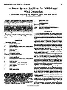
Figure 1: A 68-bus and 16-generator power system
Figure 1 shows the power system used in this study. The power system consists of 5 coherent groups representing a reduced order of the New England and New York interconnected system. The thick lines indicate the major weak tie lines that cause the low frequency inter-area oscillations. Details of power system parameters are given in [9]. 3
PROPOSED POWER SYSTEM STABILIZER TUNING METHOD
3.1 Hierarchical genetic algorithm (HGA) Each hierarchical chromosome consists of a multilevel of genes. Figure 2 shows the HGA chromosome representation with one-level control genes and parametric genes including the interface system of HGA chromosome structure and simulation package. With this configuration, the control genes are analogous to the PSS locations. The control gene signified as “0” in
15th PSCC, Liege, 22-26 August 2005
the corresponding site, is not being activated meaning that the PSS at the corresponding location will not be installed into the power system during the simulation. Parametric genes are analogous to the PSS parameters to be optimized. Using the HGA concept, locations and PSS parameters can be simultaneously tuned.
G2
6
5
2
48
G7
54
18
53 G1
23
17 15
G8
Figure 2: Hierarchical chromosome structure and system interface
3.2 Parallel micro genetic algorithm Typically, if the population size in simple GA is too large, the simple GA tends to take longer time to converge upon a solution. Conversely, if the population size is too small, it is in danger that simple GA can converge to a suboptimal solution. The simple GA cannot apply a small population size due to the lack of enough diversity in the population pool to escape from the local optima. In this paper, a micro-GA presented in [6] is used. Additionally, multipopulation evolutionary concept and parallelization are new features to implement in this study. A single population micro-GA performs well on a wide variety of problems. However, better results can be obtained by introducing multiple subpopulations. The proposed parallel micro-GA models the evolution of a species in a similar way to nature. Figure 3 shows the implementation of proposed parallel micro-GA. The parallel micro-GA is implemented through a Dynamic Host Configuration Protocol (DHCP) server. For each computer node, it is divided into multiple subpopulations. These subpopulations evolve independently of each other for a certain number of generations. Then, the migration process is achieved by distributing the best individual between the subpopulation. The scheme of migration provides genetic diversity occurring in the subpopulation by exchanging of information between subpopulation. The procedure of the parallel micro-GA can be described as follows:
Session 28, Paper 2, Page 2
Figure 3: Parallel micro genetic algorithm
Step 1: Master computer initializes the system counter to zero. Step 2: Each computer node initializes the generation counter to zero. Step 3: Each computer node loads the best individual from the database and keeps the loaded solution in the subpopulation 1, then initializes the rest population. Step 4: Each subpopulation for each computer node performs micro-GA by executing 5 operation steps as follows; Step 4.1: Evaluate the fitness of each individual. Step 4.2: Perform the tournament selection. Step 4.3: Perform the discrete recombination. Step 4.4: Perform elitism mechanism. Step 4.5: Check convergence. If converged by the constraint that the best fitness is different from average fitness by 5% or less, then reinitialize the subpopulation by keeping the recent best individual and send it to the database through DHCP server. The database is required to store set of obtaining solutions. A prototype database system has been implemented in Microsoft Access 2000 in Windows XP professional operative system. Microsoft Open Database Connectivity (ODBC) driver is used to enable communication between database management systems and SQL-based applications. Master computer can be used to collect results from the database, and to insert test solution into the database without interrupting the operation of each computer node. 3.3 Formulation of problem 3.3.1 Linearized model of power system and PSS structure A linear representation of an open-loop power system is obtained around the nominal operating point. Each generator is equipped with a simplified exciter and is represented by a 5 state transient model. The state equations of a linearized power system (A ,B ,C ,D) in Figure 1 can be expressed as:
15th PSCC, Liege, 22-26 August 2005
∆x& = A∆x + B∆uPSS , ∆y = C ∆x + D∆uPSS , ∆uPSS = K PSS ∆ω ,
where,
(1)
∆x = [∆δ , ∆ω , ∆ed′ , ∆eq′ , ∆E fd ]
T
,
(5n×1);
∆y = ∆ω , (m×1); ∆δ denotes the deviation of rotor
angle, (n×1); ∆ω is the deviation of rotor speed, (n×1); ∆ed′ and ∆eq′ are the deviations of transient internal voltage of a generator in d-axis and q-axis, respectively, (n×1); ∆E fd is the deviation of field voltage, (n×1); K PSS is the diagonal controller with designed PSSs as diagonal elements, (m×m); ∆uPSS is the control output signal of K PSS , (m×1); m and n are the numbers of machines and PSSs, respectively. Note that the system (1) is an MIMO control system and is referred to as the nominal plant G. The transfer function of PSS is defined as: ∆uPSS ,i = K i ⋅
sTw 1 + sT1i 1 + sT3i ⋅ ⋅ ⋅ ∆ωi , 1 + sTw 1 + sT2i 1 + sT4i
(2)
where, i=1,…, m, ∆uPSS ,i and ∆ωi are the control output signal and the rotor speed deviation at the i th machine, respectively; Ki is a controller gain; Tw is a wash-out time constant (s); and T1i , T2i , T3i and T4i are time constants (s). In this paper, Tw is set to be large enough and can be considered as a constant (10 s). The control parameters Ki , T1i , T2i , T3i and T4i are searched based on the objective function explained in the following subsection.
3.3.2 Objective function In derivation of the objective function, damping performance, robust stability of control system against system uncertainties, numbers of PSSs are taken into consideration. The main purpose of the PSS controller is to improve the system damping following any disturbances, therefore, the damping ratio ( ζ ) is used as a design specification. Assuming that eigenvalues corre-
Session 28, Paper 2, Page 3
sponding to the mode of oscillation can be determined as −σ ± jωd , the damping ratio is defined as:
ζ =
−σ
(3)
σ 2 + ωd 2
The D-stability region as shown in Figure 4 is used to guarantee the desired damping ratio and the real part of control modes. For the robust stability of a system, the plant uncertainty is modeled as a multiplicative form demonstrated in Figure 5 [10]. ∆ m is a stable multiplicative uncertainty. Based on the small gain theorem, the closed loop system will be robustly stable if ∆m