modelling for component design because of its excellent .... A context- free ... First, reuse of class libraries ... this pattern of interaction explicitly in a role model .... SC Head. SC Participant. SC Tail. SC Predecessor. SC Successor. Figure 7.
tion of the object-oriented programming and design. ... ted analysis and design (OOAD) are used at different ..... /library/content/03July/2000/2169/2169.pdf.
that are haunting system companies such as automotive and avionics companies ..... âSimulation Software Developmentâ, 4:155â182, 1994. Available from: .... Distributed Computing (ISORC),, pages 363 â 369, Orlando, Florida,. 2008. IEEE.
Studies by Flanagan and Norman (1983) compared the âlast ... Flanagan, 1980) which indicate a mean deviation in the ..... James, W. (1954) A new approach to.
Hwang and Takane have proposed a new component-based SEM method named ..... a) Given the quality of the products and services offered by âyour.
The current enterprise modelling tools such as System Architect .... Process diagram. Diagram of logistic network. Organisation decompo- sition chart with roles.
Modelling involves system analysis of enterprise architectures that ... Various types of dependencies that specify the enterprise architecture types (www.cio.gov).
Oct 30, 1999 - as design specifications and class instances are seen as candidate designs. ..... For Future illustration, we show a sample instance of the class.
Greenwich, London, UK. ... The future of many companies will depend to a large extent on their ... integrated software environment, based on a common data.
This paper is about modelling dynamic dependencies of com- ponents as ... with ∀〈a,b〉∈M ul(b = ∗ ∨ a ≤ b) ... In the following, we will model dependencies ... Dependency Precedence (preexp : Dep → Exp): If the number of components.
x4. 1 x4. 2 x4. 3 x51 x52 x53 x. 71 x. 72 x8. 3 x8. 2 x8. 1. 4. 5. 6. 7. 8 x'61. Fig. 6. ..... ε. )( max. ≤. +. X. A. ,. (16) where max ε is the error limit of precise condition:.
This paper reviews the literature on role playing in design and examines the ... argued, can be part of a design approach that is attentive to social change.
and dynamic interactions with converging hardware and software, spaces and servicesâ. .... Four groups of four to five students took part in the workshop of one afternoon, in a studio. ..... photographic results, for example by playing through a nu
tools still have a monolithical software design which is difficult to ... will be on a hybrid integration approach for M&S tool components ..... http://www.oasis-open.org/cover/xmlAndPetriNets.html. As shown in .... His Email and Web ad- dresses ...
Of course, limitations are a necessary property of interfaces; the line must be drawn on functionality somewhere. Acknowledgments. We thank Kevin Sullivan for ...
validating a VDSL application shows the effectiveness of the method. Categories and Subject Descriptors. J.6. [Computer-Aided Engineering]: Computer-Aided ...
theory modelling and role-modelling and assists nurses to develop expertise in its use. ..... terms of the APAM model as a move from maladaptive equilibrium to ...
component framework allowing the designer to develop a virtual embedded system ... partitions of hardware and software and hardware-based notations and ..... we separate the information required for each standard/custom component into three ..... Sys
This thesis addresses the problem of how to build adaptive software systems. These systems ...... Design) approach to developing adaptive software systems.
ing and error prone activities, e.g., by generating code di- rectly from detailed ..... generate ADA code running on the PolyORB middleware, and ADA or C code ...
out of which âall interesting or usefulâ connectors can be constructed by those connector .... In other words, it blocks a write operation on its source end or a take ...
Aug 31, 2007 - Iteration forms a recurring theme across much of design literature. However ... understanding of productivity is likely to differ from a designer's.
Jan 31, 2012 - D4.4b. Document Title. Integrability of design modelling solution. Version. 1.0. Status. Final. Work Package. WP 4.4. Deliverable Type. Report.
keywords Self-timed circuits, concurrency models, token-ring LAN adaptor, bus controller, ... expansion, signal transition graphs, implementation. ..... gain simultaneous access to a critical region) but not of so-called liveness ..... (fag;fb; cg;0)
Royal Melbourne Institute of Technology, Australia .... software development. Related ideas were first ..... Enterprise 1 may be a manufacturing company.
Proceedings of the 33rd Hawaii International Conference on System Sciences - 2000
Role Modelling for Component Design Liping Zhao Department of Computer Science Royal Melbourne Institute of Technology, Australia [email protected] Elizabeth Kendall Department of Computer Science Royal Melbourne Institute of Technology, Australia [email protected] Abstract Components are collections of co-operating entities [18]. New abstractions and techniques are required for component engineering so that proper emphasis can be placed on interaction, co-operation, and collaboration. In this paper, we present an approach to component design that is based on role modelling. We propose role modelling for component design because of its excellent support for many of the criteria, rules, and principles that form the basis of modularity. As role models can be employed for analysis, design, and implementation, they also provide a direct mapping to applications that can be traceable throughout a component's lifecycle.
1. Introduction More than two decades ago, Yourdon and Constantine defined a module as "a lexically contiguous sequence of program statements, bounded by boundary elements, having an aggregate identifier" [28]. They proposed two key techniques -- coupling and cohesion -- for evaluating and measuring the connections and dependency between software components. Since then, twenty years on, software technologies have advanced tremendously and programming languages have evolved several generations. Yet Yourdon and Constantine's classic definition is still at the heart of modular organisation, which is also known as The Linguistic Modular Units Principle [16]. Coupling and cohesion are still fundamental to modular development [19]. Extending Yourdon and Constantine's modular design, Meyer introduces a set of complementary properties: five criteria, five rules, and five principles of modularity (Figure 1) [16].
Figure 1. Modularity Criteria, Rules, and Principles (After [16])
Taken collectively, these 15 properties cover the most important requirements of modular design. We suggest that they be the foundations of building reusable and extensible components, as summarised below. 1) Composability and Decomposability. A module, or component must have Composability and Decomposability in that it can be composed with other components to form a larger component or decomposed into smaller components. In order to have composability and decomposability, a component must satisfy the Open-Closed principle. A component is organisationally closed if it is autonomous and self-organising, similar to a living system. A component is structurally open if it is available for extension. The Open-Closed principle ensures that a component maintains its internal stable form and at the same time opens for extension. Composability and Decomposability are also the result of Direct Mapping; a modular structure should correspond to the structure of the problem. 2) Continuity and Protection. A component must satisfy the Continuity and Protection criteria. Continuity means that a small change to a
0-7695-0493-0/00 $10.00 (c) 2000 IEEE
1
Proceedings of the 33rd Hawaii International Conference on System Sciences - 2000
system should be localised within only one or a very few components. A component that satisfies the protection criterion will reduce the propagation of side effects of an abnormality that occurs at run time. Both of these criteria are closely related to Few Interface (every component should communicate with as few others as possible), Small Interface (two components should exchange as little information as possible), Information Hiding, and Single Choice (a strong form of information hiding). All of these are extensions of low coupling and high cohesion. 3) Understandability and Semantics. With the Understandability criterion, a user of a component can understand it without needing knowledge about other components. To satisfy this criterion, a component must have an Explicit Interface (the communication between two components should be public to other components), be a Linguistic Modular Unit, and have Self-Documentation (all the information about the component should be included in the component). In this article, we present an approach to component design that is based on role modelling. We propose role modelling for component design because of its excellent support for many of the criteria, rules, and principles presented in Figure 1. In particular, role modelling provides support for Composability and Decomposability; Direct Mapping; Explicit Interface; and Understandability and Semantics. Role models have been effectively utilized for component composition and decomposition [10, 21]. As role models can be employed for system analysis, design, and implementation, they provide a direct mapping to the application that is traceable throughout the software lifecycle. Role models also yield rich semantics for component interfaces and context. In this paper, we argue that every component must have a specific context. A component only works in some situations; it is impossible for it to be valid or even relevant in all situations. A context- free component does not exist in reality, as every component is developed for some specific purpose. Components developed for the same context thus share some common features. On the other hand, they can differ in their services. A component should hold a context reference in its interface, and role models are an excellent vehicle for capturing
and representing dependencies.
context
and
contextual
The rest of the article is organised as follows. Section 2 discusses some broad issues of component engineering. Section 3 gives an overview of roles and role models and their relevance to component design. Section 4 illustrates component design with role models. Finally, we review related work on software components and discuss our contributions and future work.
2. Problems of Building Software Components
Reusable
2.1. Interactions and Collaborations Software components need to be able to cooperate with one another to perform a task or to achieve a goal. In component based development, interactions and collaborations are therefore of paramount importance. As pointed out in [18], object oriented programming "too often concentrates on individual objects, instead of whole collections of objects. Focusing on individual objects is misleading and often results in software which cannot be used as components." In an application where objects are the only structuring facility or the only unit of abstraction, it becomes very difficult to extract and package a suitable subset or subsystem [18]. Therefore, the primary problem in building reusable software components seems to be the need for a shift of focus from the level of individual objects to the level of subsets of interacting, collaborating entities. 2.2. Interface Translation Another major obstacle in building reusable software components is the lack of standards. Components developed independently cannot be readily integrated into an application. Although some interoperability standards are recently available which define mappings from a client component to a server component [17], such standards do not provide any means for specifying the interfaces between the client and server components [23]. One solution to overcome this problem is to reproduce the server components to conform to the interface requirements of the client components. This suggests that the server
0-7695-0493-0/00 $10.00 (c) 2000 IEEE
2
Proceedings of the 33rd Hawaii International Conference on System Sciences - 2000
components cannot be reused. Another solution is to use an adapter or wrapper to convert the interface of a client component into the interface of a server component. One such adapter is called a Conciliator [23], which is a hybrid of the Façade and Adapter patterns [5]. However, components that need an adapter are not actually reusable components, because they are not directly composable. The use of adapters and wrappers also violates the properties of Direct Mapping; Uniform Access; and Explicit, Few, and Small Interfaces. This is because adapters and wrappers act as intermediaries, adding potentially complex links in the communication chain between a client object and its target component. 2.3. Reuse through Inheritance Object-orientation has made many conjectures regarding software reuse. However, while an object can be regarded as a basic module, or component, it is not inherently reusable. One may argue that class libraries and code inheritance can achieve reuse. Yet, this form of reuse violates many of the properties in Figure 1. First, reuse of class libraries means that the developer has to know the details of the source code. This violates the Protection criteria and the Information Hiding rule. Reuse through source code makes module protection impossible. Second, reuse via inheritance is similar to copy and paste [24]. This makes it difficult for the developer to decide what to inherit and what to override. It also violates the Decomposability criteria because inheritance means that a subclass obtains all of the superclass' features and behaviour as a monolithic block. A reusable component should therefore hide design and implementation details from the clients, and highlight the interface properties. Further, a reusable component should be readily integrated into an application and composed with other components. A reusable component therefore goes beyond an object inheritance. 2.4. Reuse through Delegation The second common argument for object reuse is delegation. With this approach, a container object delegates behaviour to an object that is inside or within it. This has been advocated as a major avenue to reuse, as new objects can be placed inside the container object, providing new behaviour. However, due to the way that object
interfaces' work, a designer who chooses delegation is faced with two options that are less than desirable. First, they can make the contained object public so it can be messaged directly. Alternatively, they can reproduce the contained object's interface in the container so a message can be passed from a client object, via the container, to the contained object. Reuse through delegation therefore either violates the Information Hiding rule or leads to a complicated chain of communication (contrary to Few, Small, Explicit Interfaces). 2.5. Non-Functionals or Ilities Another key concern is the development of component-based systems which meet required system- wide criteria on non-functionals or ilities [26]. These include reliability, security, and responsiveness. While a tiered approach has been proposed, extra language support, such as AspectOriented Programming (AOP) [11] may be a promising alternative.
3. Role and Role Model 3.1. Overview and Illustration Roles and role models [1, 12, 13, 20] are relatively new abstraction mechanisms in object-oriented software development. Related ideas were first documented in 1990 as contracts [7]. Harrison and Osher [6] also discussed the importance of object roles and perspectives. However, the first publications explicitly on role models appeared in 1995 [20]. A role model is an abstraction that describes patterns of interactions between a set of entities. The entities play certain roles in a given context; the context is captured by the role model. A role model depicts frequently occurring but transient relationships between entities or objects that are working together to perform a certain task or accomplish a certain goal. As an example, we consider a high level view of process management in manufacturing.
0-7695-0493-0/00 $10.00 (c) 2000 IEEE
3
Proceedings of the 33rd Hawaii International Conference on System Sciences - 2000
(shown as rectangles below the horizontal line) play the various roles, as indicated by the dashed arrows.
Customer
Manager
Functional Group
Role Model Assembly Plant Manager
Client QA
aCustomer
Figure 2. A Class Diagram of Manufacturing Process Management
Figure 2 (a UML class diagram) shows static relationships between customers, managers, and various functional groups (assembly, quality assurance, and a repair shop). An instance collaboration diagram for this same application is depicted in Figure 3. Figure 3 shows object interactions in a particular collaboration -- a customer requests a new product. In the figure, the message sequence is numbered and the direction of messaging is shown as an arrow. When a customer makes a request for a new product, the request propagates through messages 2 to 5, where the plant manager delegates work to assembly and then to QA. The product is then delivered to the customer in message 6. aCustomer
aRepairShop 1: newProduct
6: product 3: completedWork
anAssembly
aPlantManager
2: newWork
Mediator
Colleague
Repair Shop
4: newWork
5: completedWork
aQA
Figure 3. Object Interactions in an Instance Collaboration Diagram
Careful observation reveals that the collaboration depicted in Figure 3 is a pattern that is characteristic of centralised communication or the Mediator pattern [5]. We can capture and abstract this pattern of interaction explicitly in a role model (Figure 4), where there are three roles: Client, Mediator, and Colleague. A role is denoted as a rounded box and the solid arrows indicate collaboration paths between the roles. The direction of the arrow represents the direction of messaging, and the solid circle on the link from the Mediator to the Colleague indicates that there is more than one Colleague. Figure 4 also shows an example of role assignment: the objects in Figure 3
aPlantManager
aQA aRepairShop
Objects in the Application anAssembly
Figure 4. A Role Model for the Object Interaction in Figure 3
The important distinction between the collaboration diagram in Figure 3 and the role model in Figure 4 is that the role model is an abstraction; the object collaboration diagram is an instance of it. Additional role model views, notation, and semantics are detailed in [1]. 3.2.
Role, Role Model, and Component Engineering
Object-oriented software engineering has to date primarily focused on classes. A class stipulates the capabilities of individual objects, whereas a role focuses on the position and responsibilities of an object within an overall structure or system. A class can be used to describe a set of objects; however, these objects exhibit common properties and a shared interface. Instances of the same class do not usually co-operate with each other, and a class does little if anything to describe object interactions. Alternatively, a role describes a set of objects that occupy the same position, hold the same responsibilities, and participate in the same collaboration. Further, a role model captures and describes a set of objects that interact and co-operate to perform a task or accomplish a goal. The capabilities of individual objects that populate an application are not enough to help us understand how the application operates. It is the same as if you want to build a house [20]. The specifications for the individual windows, doors, and shelves are not sufficient for you to build the house. You need to know about the relationships and responsibilities for these objects. Pfister and Szperski [18] describe a component as "a collection of co-operating objects." We agree
0-7695-0493-0/00 $10.00 (c) 2000 IEEE
4
Proceedings of the 33rd Hawaii International Conference on System Sciences - 2000
that, as discussed in section 2.1, interactions and co-operation are of paramount importance for components. Further, we propose that role models are an excellent vehicle for capturing, abstracting, and assembling component collaborations. However, we propose an alternative granularity to Pfister and Szperski. Components interact by playing roles. But, in a given implementation, there may be one component per role, more than one component per role, or more than one role per component. This is in contrast to Pfister and Szyperski, who seem to be stipulating that only the last mapping is appropriate; there must be more than one role per component. (These mappings and compositions are discussed further in section 4.) Our alternative granularity is based on the premise that components should be composable and decomposable. In a quality design, components are in fact centers or noticeable, recursive structures. "This leads to collections of recursive and hierarchical centers which are integrated at all levels of scale and which reinforce one another" [4]. Role models, we propose, are a representation for assembling components; they are subsets or subsystems of interacting, cooperating components. As discussed in section 4, role models can in fact be composed from other role models. Role models and components are both centers.
3. A role model provides richer semantics that go beyond an interface specification in a class. All the roles within a role model work together and collaborate on a specific task or separation of concern. The specification for a role goes beyond an interface; it is a full specification for the responsibilities and collaborations that the role represents in the given context. However, different components or entities can appear and play the role, provided they meet the specification. 4. A role model is dynamic. A given component can play roles in different role models. Additionally, different components can come and go, playing the same role. 5. A role model is independent of implementation. A role model and the roles within it provide a specification without any restriction on how it may be implemented. In the next section, we illustrate how component design can be accomplished with role models. We emphasise component composition. Our research also addresses other areas of the component lifecycle, such as the impact of roles on component analysis and implementation. However, due to brevity, most of these considerations are beyond the scope of this paper.
4. Component Composition
Design
With
Role
3.3. Summary We propose that, during analysis, design, and implementation, components can be identified on the basis of the roles that they play. That is, in our approach, roles correspond (in a one-to-one, oneto-many, or many-to-one mapping) to components.. To summarise, we consider role models to be relevant to component design in the following ways: 1. A role model is context-specific. A role model focuses on a single purpose of object collaboration and provides a context in which objects play roles for this purpose. A role model captures and provides a context in which we can describe each component (role). 2. A role model captures a pattern of object interaction. Each role model is an abstraction that can be instantiated by specific applications.
4.1. Additional Role Models Role models can be employed during component design. Basically, the roles that a given component needs to play have to be identified and composed during design. This approach has been utilized during framework design [21]. It has also been employed for agent design [Kendall99b]. With this approach, an agent class, a class in a framework, and a component can be designed by composing or assembling the individual roles that it needs to play. That is, each role must be fully specified and then the responsibilities and collaborations must be composed to form the component. To illustrate role model composition, we introduce two additional role models: Bureaucracy and Supply Chain. 4.1.1. The Bureaucracy Role Model
In Figure 4, we showed a role model that is pertinent to centralised communication -- the
0-7695-0493-0/00 $10.00 (c) 2000 IEEE
5
Proceedings of the 33rd Hawaii International Conference on System Sciences - 2000
Mediator pattern. We redraw Figure 4 in Figure 5, where we emphasise two key roles: Mediator and Colleague. Client
Colleague
Mediator
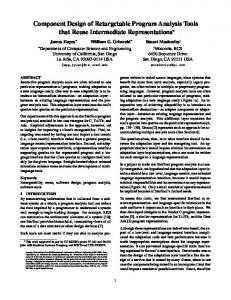
SC Predecessor
SC Head
SC Successor
SC Participant
SC Tail
Figure 7. Supply Chain: Top Level Role Model Figure 5. Role Model of the Mediator Pattern
In a multilevel hierarchical organisation, the Mediator pattern is in fact a role model that can be aggregated within larger role models. One such multilevel role model is called the Bureaucracy pattern [22], as in Figure 6, where a Mediator has now become a Manager and a Colleague has become a Subordinate. There are six roles involved in Bureaucracy: Director, Director Client, Manager, Subordinate, Clerk, and Clerk Client. In the role model, a manager and a subordinate must also be a clerk (indicated by the triangle for refinement), and a director must also be a manager. A client is free to interact with any part of the hierarchy. However, a director has additional responsibilities for error handling and managing the entire hierarchy. Clerk
ClerkClient Manager
We have introduced Role Responsibility Collaboration (RRC) cards [Kendall98, Kendall99b] as a simple way to document the responsibilities and collaborations of a role in a given role model. Sample RRC Cards for the SC Predecessor, SC Successor, and SC Participant roles are provided in Figure 8. As shown in the cards, the responsibilities can be viewed to belong to lower level (aggregated) roles, such as Customer, User, Provider, and Operator. Additional notation [1, 10] can be used to specify a role's full semantics, including its interface(s) and its states. Role: Supply Chain (SC) Predecessor Responsibilities: Collaborators: initiate and complete supply (send, receive message) negotiation (Customer) SC Successors receive supplies (User) < (receive message from) SC Successors
A Supply Chain is a common pattern of collaboration [8, 10] (Figure 7); it often appears in agent systems, manufacturing, and other enterprises. It is similar to the Chain of Responsibility pattern [5], except that each link in the chain is required to deliver a product or perform a service for its predecessor. A Supply Chain (SC) is comprised of suppliers and consumers. A consumer can have many suppliers, but a supplier usually only has one consumer in any given supply chain. At the highest level, a supply chain is made up of SC Predecessors and SC Successors. A predecessor can have many successors. As shown in Figure 7, a SC Participant is both a predecessor and a successor, while a SC Head is a specialization of a predecessor, and a SC Tail refines a successor.
Figure 8: Role Responsibility Cards for Supply Chain Role Model
0-7695-0493-0/00 $10.00 (c) 2000 IEEE
6
Proceedings of the 33rd Hawaii International Conference on System Sciences - 2000
4.2. Role Model Composition Any application will in fact encompass many role models. During application analysis, relevant role models should be identified. This can be done from scratch by identifying entities (roles) and collaborations in an application. Alternatively, an application can be examined to identify patterns of interaction. For example, in Agent Enhanced Workflow (AEW) and flexible manufacturing [8, 10], an agent represents an individual, organization, or machine that can do work. The agent is responsible for assigning and scheduling work for the entity that it represents, and agents depend on each other to deliver products and/or work. In other words, some agents supply work or products, while others consume it. In addition, the agents may be arranged hierarchically, reflecting an enterprise's structure. Some may be managers, while others are subordinates. For example, three agents may represent an end customer and two enterprises, respectively. The Customer deals directly only with Enterprise 1. Enterprise 1 depends on Enterprise 2 for supplies or work, and Enterprise 2 in turn depends on Enterprise 3. At the highest level, the application (Figure 9) is an instantiation of the Supply Chain role model. The Customer is the SC Head, Enterprise 1 is a SC Participant, and Enterprise 2 is a SC Tail. Enterprise 1 is a SC Successor to the Customer, but it is a SC Predecessor to Enterprise 2. SC Predecessor
SC Successor
Manager
Customer
aPlantManager
SC Predecessor
SC Successor
Subordinate
aQA
Enterprise 2
anAssembly aRepairShop Enterprise 1
Figure 9. Bureaucracy with Supply Chain Model for Agent Enhanced Workflow Application
However, each enterprise in the supply chain can be made up of several components. For example, Enterprise 1 may be a manufacturing company with a hierarchical structure and agents to represent each domain. In this case, both the Bureaucracy and Supply Chain role models appear (Manager and Subordinate in Figure 9). It is the responsibility of the Plant Manager to be the SC Successor to the Customer, but it is the Assembly
functional group that requires input from Enterprise 2, so it is the SC Predecessor in that context. In Figure 9, the relevant role models appear in the top half of the diagram, while the entities in the application that play the roles appear in the bottom half. As in Figure 4, dashed lines indicate role assignments. The Plant Manager must play all of the lower level roles found in a Supply Chain Successor. (In a more detailed view in Figure 8, these consist of Negotiator, Producer, and Supplier). In addition, the Plant Manager must be able to play the role of a Manager. Likewise, the Assembly group must be a Supply Chain Predecessor in addition to satisfying the responsibilities of a Subordinate. Both entities must appropriately address context switching as they go from role to role. 4.3. Role and Context Composition The consequence of role model composition is role composition. If an entity is going to play more than one role at a time, these roles have to be composed. Usually role model composition occurs during application analysis; role composition, on the other hand, occurs during design. As mentioned in Section 3, an individual role model focuses on a single context. When a role is assigned to a particular object, the object plays that role only in the given role model. A specific role is relevant only to a given context. When different role models are composed, it is important to indicate the context in which a role exists. As an example, Figure 10 illustrates the roles that an agent component plays in agent enhanced workflow. Because workflow or manufacturing formations can vary, each agent must be capable of being a Supply Chain Participant; this is fact means that it must be able to play the four lower level roles in Figure 8 (Customer, User, Provider, and Operator). Additionally, agent hierarchies will be variable, so an AEW agent should be able to be a Manager, a Subordinate, or a Client of a Bureaucracy. As shown in Figure 10, each role is represented as a role-context pair. Thus, an agent plays a customer role in Supply Chain and plays a manager role in Bureaucracy, and so on.
0-7695-0493-0/00 $10.00 (c) 2000 IEEE
7
Proceedings of the 33rd Hawaii International Conference on System Sciences - 2000
Customer - Supply Chain Participant User - Supply Chain Participant
4.4. Role Based Implementations 4.4.1. Object-Oriented Programming Approach
A role model can be implemented using an existing object-oriented programming language. Several patterns [5] can be used to map a role model into a class model. For example, the Role Object pattern [2] can be used to design the role composition shown in Figure 10, as depicted in Figure 11. A class is required for every role; the four roles that appear in the Supply Chain Participant (Figure 8) are shown. A SC Participant has added behaviour; its Customer, User, Provider, and Operator are refinements of the four base roles. This is depicted with an inheritance relationship in Figure 11. Further, the Manager, Subordinate, and Client roles from the Bureaucracy role model must be available. These are three additional role components, and Manager and Subordinate are subclasses of class Clerk.
component modularity and reuse because it either violates Information Hiding or results in complicated interfaces and multi-step communication between a client and its target component. An alternative approach to role implementation, centering on aspect- oriented programming [11], has been investigated by one of the present authors [9]. As aspect oriented programming is also a promising approach to capturing and implementing application non-functionals or ilities (section 2.5), it is anticipated that this will be a fruitful area of research for component engineering. Additional details are beyond the scope of this paper, but can be found in [9]. Figure 11. Role Object Pattern for Supply Chain & Agent
Role
Bureaucracy role
Clerk
Client
Supply Chain Role
Customer
Customer Participant
Manager
User
User Participant
Provider
Provider Participant
Subordinator
Bureaucracy Role Objects 4.4.3. Role Synergy
Agent implementations based on the Role Object pattern have been developed at British Telecom and at Royal Melbourne Institute of Technology in Australia. A hashtable or other container can be used to hold the roles, and all behaviour and context switching is delegated to them. A similar system, termed a plug-in architecture, has been developed to address mobile agents [27]. Role components are assembled to form an agent, as determined by the roles that must be played. Because code size is particularly important for mobile agents, only required roles are built into the agent. 4.4.2 Aspect-Oriented Programming Approach
The designs discussed in sections 4.4.1 and 4.4.2 are appropriate when role assignments are dynamic and variable. That is, any AEW agent can play any of the roles in Figures 10 and 11. Research completed by Riehle [21] has concentrated on applications where role assignments are more long term. In this case, role composition needs to be carefully addressed during design to ensure that the class, agent, or component can efficiently satisfy the requirements of a narrow set of roles. This may lead to role synergy, where several roles are merged into a new composite role(s) that is more than a sum of the individual roles. Further details can be found in [21].
The object-oriented design in Figure 11 has its limitations and drawbacks. In particular, roles are addressed solely through delegation. As discussed in section 2.4, delegation can be problematic for
0-7695-0493-0/00 $10.00 (c) 2000 IEEE
8
Proceedings of the 33rd Hawaii International Conference on System Sciences - 2000
5. Discussion We have proposed role models as abstractions and representations for components, based on the premise that components collaborate with each other in a specific context. We propose that role modelling is pertinent to component engineering throughout the lifecycle, and we have illustrated our approach with emphasis on component design. Roles have often been proposed as abstractions for interaction [20, 15, 3]. However, the key issues or questions have been the implications on design and implementation. Recent work presented in [21, 9] has brought role modelling into other phases of the software lifecycle, and these techniques have been summarised in section 4. Of course, much more work needs to be done, in role synergy and related areas, so that role modelling can be used to yield efficient and near optimal component designs.
[10] E.A. Kendall. "Role Modelling for Agent System Analysis, Design, and Implementation," International Conference on Agent Systems and Applications/ Mobile Agents (ASA/ MA'99),Palm Springs, October, 1999. (Submitted) [11] G. Kiczales, J. Lamping, A. Mendhekar, C. Maeda, C. Lopes, J. - M. Loingtier, and J. Irwin, "Aspect Oriented Programming," Xerox Corporation, 1997. www.parc.xerox.com/spl/projects/aop/ [12] B.B. Kristensen. “Object-Oriented Modelling with Roles”, OOIS'95, Proceedings of the 2nd International Conference on Object-Oriented Information Systems, Dublin, Ireland, 1996. [13] B.B. Kristensen and D. C. M. May. ``Component Composition and Interaction''. Proceedings of International Conference on Technology of Object-Oriented Languages and Systems (TOOLS PACIFIC 96), Melbourne, Australia, 1996. [14] B.B. Kristensen and Osterbye, K., “Roles: Conceptual Abstraction Theory and Practical language Issues”, Special Issue of Theory and Practice of Object Systems (TAPOS) on Subjectivity in Object-Oriented Systems, 1996. [15] E.C. Lupu and Sloman, M., "Towards a Role Based Framework for Distributed Systems Management," Journal of Network and Systems Management, 1996.
6. References
[16] B. Meyer. Object-Oriented Software Construction. Prentice Hall. New Jersey, 1998.
[1] E. P. Andersen. Conceptual Modeling of Objects: A Role Modeling Approach, Ph.D Thesis, University of Oslo, 1997.
[17] Object Management Group (OMG). The Common Object Request Broker: Architecture and Specification. Version 2.1. August, 1997.
[2] D. Bäumer, D. Riehle, W. Siberski, and M. Wulf. "The Role Object Pattern." In Proceedings of 4th Conference on Pattern Languages of Programs, 1997.
[18] C. Pfister and C. Szyperski. "Why Objects Are Not Enough," Component Users Conference, Munich, Germany, 1996
[3] B.J. Biddle and E. J. Thomas. Role Theory: Concepts and Research, New York, R. E. Krieger Publishing Co., 1979.
[19] R.S. Pressman. Software Engineering: A Practitioner's Approach. McGraw-Hill. New York. 1997.
[4] J.O. Coplien. "On the Nature of The Nature of Order," www.bell-labs.com/~cope, 1997.
[20] T. Reenskaug, P. Wold, and O.A. Lehne. Working with Objects, The OOram Software Engineering Method, Manning Publications Co, Greenwich, 1996.
[5] E. Gamma et al. Design Patterns: Elements of Reusable Object-Oriented Software. Massachusetts, Addison-Wesley, 1995. [6] W. Harrison and H. Osher, "Subject- Oriented Programming (a critique of pure objects)," in Proceedings of the Conference on Object Oriented Programming: Systems, Languages, and Applications, Washington, D. C. September, 1993. pp. 411 - 428.
[21] D. Riehle and T. Gross, "Role Model Based Framework Design and Integration," OOPSLA'98, Proceedings of the 1998 Conference on Object Oriented Programming Systems, Languages and Applications, ACM Press, 1998. [22] D. Riehle. "Bureaucracy", in Pattern Languages of Program Design 3, R. Martin, D. Riehle, F. Buschmann (Ed.), Addison Wesley, 1998, pp. 163 - 185.
[7] R. Helm, I. M. Holland, and D. Gangopadhyay, "Contracts: Specifying Behavioral Compositions in Object- Oriented Systems," Object Oriented Programming, Systems and Lanugages, ECOOP/ OOPSLA '90 Proceedings, October, 1990, pp. 169 - 180.
[23] G. Smith, J. Gough, and C. Szyperski. "Conciliation: The Adaptation of Independently Developed Components". Second International Conference on Parallel and Distributed Computing and Networks (PDCN '98). pp. 31-38. Brisbane. 14-16 Dec. 1998.
[8] E.A. Kendall. "Agent Roles and Role Models: New Abstractions for Multiagent System Analysis and Design," International Workshop on Intelligent Agents in Information and Process Management, Germany, September, 1998.
[24] C. Szyperski. "Component-Oriented Programming -- A Refined Variation on Object-Oriented Programming". The Oberon Tribune, Vol. 1 (2), 1995.
[9] E.A. Kendall. "Role Model Designs and Implementations with Aspect Oriented Programming," OOPSLA'99, Denver, November, 1999.
[25] C. Szyperski. Component Software - Beyond ObjectOriented Programming, Addison- Wesley / ACM Press, 1998 . [26] C. Szyperski and R. Vernik, "Establishing System- Wide Properties of Component-Based Systems: A Case for Tiered Component Frameworks," Position Statement to OMG-
0-7695-0493-0/00 $10.00 (c) 2000 IEEE
9
Proceedings of the 33rd Hawaii International Conference on System Sciences - 2000
DARPA-MCC Workshop on Compositional Architectures, Monterey, January, 1998.
Software
[27] M.T. Tu, F. Griffel, M. Merz, and W. Lamersdorf, "A Plug-In Architecture Providing Dynamic Negotiation Capabilities for Mobile Agents," Mobile Agents: Second International Workshop (MA'98), Stuttgart, Germany, September, 1998, pp. 222 - 236. [28] E. Yourdon and L. Constantine. Structured Design. Prentice Hall. New Jersey, 1978.
7. Acknowledgements We thank our three anonymous referees for their helpful comments on this article.