the onset of instability. That model is used to describe nonlinear roll waves. 1. Introduction. Intermittent surges have been observed in mud flows in flooded rivers ...
c 2004 Cambridge University Press J. Fluid Mech. (2004), vol. 519, pp. 33–54. � DOI: 10.1017/S0022112004000801 Printed in the United Kingdom
33
Roll waves in mud By N. J. B A L M F O R T H1 1
AND
J. J. L I U2
Departments of Mathematics and Earth & Ocean Science, University of British Columbia, 1984 Mathematics Road, Vancouver, BC, Canada V6T 1Z2 2
Division of Geological and Planetary Sciences, California Institute of Technology, Pasadena, CA 91125, USA
(Received 3 December 2003 and in revised form 13 April 2004)
The stability of a viscoplastic fluid film falling down an inclined plane is explored, with the aim of determining the critical Reynolds number for the onset of roll waves. The Herschel–Bulkley constitutive law is adopted and the fluid is assumed two-dimensional and incompressible. The linear stability problem is described for an equilibrium in the form of a uniform sheet flow, when perturbed by introducing an infinitesimal stress perturbation. This flow is stable for very high Reynolds numbers because the rigid plug riding atop the fluid layer cannot be deformed and the free surface remains flat. If the flow is perturbed by allowing arbitrarily small strain rates, on the other hand, the plug is immediately replaced by a weakly yielded ‘pseudo-plug’ that can deform and reshape the free surface. This situation is modelled by lubrication theory at zero Reynolds number, and it is shown how the fluid exhibits free-surface instabilities at order-one Reynolds numbers. Simpler models based on vertical averages of the fluid equations are evaluated, and one particular model is identified that correctly predicts the onset of instability. That model is used to describe nonlinear roll waves.
1. Introduction Intermittent surges have been observed in mud flows in flooded rivers and flumes (Engelund & Wan 1984; Coussot 1997). The phenomenon has been theoretically rationalized (Coussot 1997; Mei 2001) as an analogue of the classical roll-wave instability which generates the patterns that decorate falling viscous films (Benjamin 1957; Yih 1963) and steepen into the shock-like structures seen in turbulent water courses (Cornish 1910; Dressler 1949). These surges can present problems to hydraulic engineers, but the flow of mud in general is a dangerous phenomenon and demands a theoretical understanding. An important property of clay suspensions like mud is that the interactions between clay particles create an extensive microscopic structure that withstands a certain stress before deforming and allowing the fluid to flow. That is, mud has a yield stress (some controversy exists over whether a real fluid actually possesses a true yield stress, Barnes 1999, but the concept is certainly a useful one and is adopted here). Moreover, on flowing, the microstructure becomes gradually broken down, with the result that the effective resistance continues to decrease with the applied stress (the shear-thinning effect). These viscoplastic effects play key roles in the fluid dynamics of mud and place this fluid in the realm of non-Newtonian fluid mechanics. Existing theoretical models of mud surges are based on simplifications of the governing viscoplastic fluid equations obtained from vertical averaging (Liu & ´ an– ´ Mei 1994; Jiang & LeBlond 1993). The procedure is much like the von Karm Pohlhausen power integral method used in the classical theory of boundary layers,
34
N. J. Balmforth and J. J. Liu
and proceeds by first prescribing a fixed vertical structure to the flow. The governing equations can then be vertically integrated to remove entirely one of the spatial variables. The shear stress is replaced by a parameterized drag term in the theory, much as in the St Venant model used in hydraulics, and for similar mathematical reasons one uncovers roll-wave instability. The model predicts moderate values for the critical Reynolds numbers for the onset of instability, and has had some success in rationalizing mud surges in terms of roll-wave instability. An unfortunate feature of vertically averaged models is that they are known to predict incorrectly the critical Reynolds number for onset of roll waves in laminar viscous films (Chang, Demekhin & Kopelevich 1993). In many situations, this error is not significant. However, it reflects an uncontrolled approximation in the theory that is difficult to gauge, especially when the theory is adapted to the non-Newtonian situation. In fact, it is not necessary to vertically average the fluid equations to explore roll-wave instability, which motivates us to proceed down different pathways in the current paper. Further motivation arises from recent work on pipe and channel flow, which suggests that yield stresses can significantly stabilize fluid instabilities, and even remove them entirely (Frigaard, Howison & Sobey 1994; Nouar & Frigaard 2001). By contrast, the vertically averaged models show no such significant effect. In fact, as we outline presently, certain stability arguments indicate that roll-wave instability is completely absent in viscoplastic films. The essence of this argument is associated with how one perturbs the regions of the flow which are not yet yielded. In uniform viscoplastic films flowing down inclined planes, one such region always occurs adjacent to the free surface, forming a rigid plug. If initial perturbations in stress leave that region intact, the plug effectively places a rigid lid on the viscoplastic film, precluding roll-wave instability. It is precisely this effect that has been used to argue that viscoplastic shear flows are far more stable than their Newtonian counterparts (Frigaard, Howison & Sobey 1994; Nouar & Frigaard 2001). Nevertheless, as we also argue below, there are different ways to perturb viscoplastic films. In particular, when there are weak downstream variations in the flow, no truly rigid plugs occur within the material and the free surface of the film can deform, to allow roll-wave instability. 2. Formulation A convenient constitutive model that incorporates shear thinning and yield stress is the Herschel–Bulkley law. Kaolin slurries, one of the prototypical viscoplastic fluids, are fit adequately by this model, as are many materials of chemical engineering. Kaolin slurries are often used in experimental models of geophysical flows (Liu & Mei 1989; Blake 1990; Griffiths & Fink 1997), in addition to being the basis of a range of industrial products. The Herschel–Bulkley law is formulated mathematically as follows: γ˙ij for τ > τy , (2.1) τij = (K γ˙ n + τy ) γ˙ and for τ < τy , (2.2) γ˙ij = 0 where the components of the deviatoric stress tensor, τ , are τj k , � � � � � � ∂ui ∂uj 1 , τ= 2 + τij τj i , γ˙ = 12 (2.3) γ˙ij ≡ γ˙ij γ˙j i . ∂xj ∂xi i,j i,j
35
Roll waves in mud (a) z
(b) z
Cross-section:
True plug U(z)
h(x, t) g
x
Y(x, t)
Uniform flow Weakly varying flow
x
u(x, z, t)
Pseudo-plug Yielding region Yielding region φ
Yield stress τγ Stress invariant
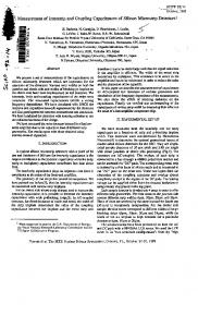
Figure 1. (a) A sketch of the geometry for a viscoplastic film flowing down an inclined plane. In (b) we illustrate the uniform equilibrium and the associated distribution of the stress invariant, together with the related distribution for the state to which an initially non-uniform flow converges at low Reynolds number.
The model has three parameters, assumed constant: K (the consistency), τy (the yield stress) and n (the power-law index). Given the constitutive law, we may write the governing equations for twodimensional incompressible flow: ρ(ut + uux + wuz ) = −px + ∂x τxx + ∂z τxz + ρg sin φ, ρ(wt + uwx + wwz ) = −pz + ∂x τxz + ∂z τzz − ρg cos φ
(2.4) (2.5)
ux + wz = 0,
(2.6)
and where ρ is density, p is pressure, φ is the angle of the inclined plane, and subscripts denote partial derivatives except for the stress components. The geometry is illustrated in figure 1. We impose a no-slip boundary condition on the inclined plane: u = w = 0 on z = 0.
(2.7)
The upper surface, z = h(x, t), is a material surface and stress free: ht + u(x, h, t)hx = w(x, h, t), � � −hx (τ − pI )|z=h · = 0. 1
(2.8) (2.9)
(We ignore surface tension, though it is easily included.) 2.1. Dimensionless form We now remove dimensions. We use the typical film thickness, H , to measure lengths transverse to the film (which we loosely refer to as ‘vertical’), and L = H / tan φ for distances downslope (loosely called ‘horizontal’); typically, � = H /L � 1, and much of our analysis will focus on this limit. We then set x = L˜ x,
z = H ˜z,
˜ w = H V w/L, t = L˜t /V , V V γ˙j k = γ˜˙ j k , τj k = ρν τ˜j k , H H
˜, u = Vu
˜ cos φ, p = ρgH p
(2.10)
and so on, where V = gH 2 sin φ/ν is a characteristic flow speed, and ν = K(V /H )n−1 /ρ is an effective kinematic viscosity. After dropping the tilde, the dimensionless
36
N. J. Balmforth and J. J. Liu
equations become: Re(ut + uux + wuz ) = −px + �∂x τxx + ∂z τxz + 1, � Re(wt + uwx + wwz ) = −pz + � 2 ∂x τxz + �∂z τzz − 1, ux + wz = 0, 2
τij = (˙ γ n−1 + B γ˙ −1 )˙ γij
for
τ > B,
γ˙ij = 0
for
τ < B,
and
� γ˙ =
2�ux
uz + � 2 wx
uz + � 2 wx
−2�ux
(2.11) (2.12) (2.13) (2.14)
� (2.15)
,
where Re = V H 2 /(νL) is a scaled Reynolds number based on the characteristic speed V , and B = τy H /(ρνV ) is the Bingham number (dimensionless yield stress). Only the stress-free surface conditions change on non-dimensionalizing: τxz = hx (�τxx − p),
�τzz − p = � 2 hx τxz
on z = h(x, t).
(2.16)
2.2. The boundary-layer model By discarding terms of order � and higher, we arrive at a simpler model from which we begin any further reductions (cf. Chang et al. 1993). From the vertical momentum equation: or p = h − z. (2.17) 0 = −pz − 1 Replacing px = hx in the horizontal momentum equation: Re(ut + uux + wuz ) = 1 − hx + ∂z τxz .
(2.18)
3. The importance of being rigid As shown in figure 1, the uniform equilibrium arrangement consists of a shearing layer supporting a truly rigid plug in which the only non-zero stress component, the vertical shear stress, lies below the yield value: h = 1, τxz = 1 − z, w = 0 and � � n (1 − B)1+1/n − (1 − B − z)1+1/n /(n + 1) if z 6 1 − B, u = U (z) = (3.1) if z > 1 − B. n(1 − B)1+1/n /(n + 1) The undisturbed yield surface lies at the height z = 1 − B, which must be positive for the film to be in motion (B < 1). Above the yield surface, only the shear stress τxz is, in principle, prescribed; τxx = −τzz is indeterminate (save for the requirement that the second invariant τ should not exceed the yield stress). The physical interpretation of this indeterminacy is that the material could be in an arbitrary ‘pre-stressed’ state provided that it is not yielding. To fix ideas on a particular situation, we adopt the simple case in which τxx = τzz = 0, which mirrors the Newtonian version of the problem. Then τ ≡ τxz = 1 − z in equilibrium, as shown in figure 1. However, the discussion below is largely independent of this choice, unless the pre-stressed plug happened to be arbitrarily close to yield. Now, if we add an infinitesimal stress perturbation to the equilibrium state, we shift the yield surface slightly, but the overlying fluid is not forced to yield. Consequently, the disturbance does not destroy the plug, nor deform the free surface, which is an essential ingredient to the Newtonian instability mechanism of a falling film. To
Roll waves in mud
37
see this mathematically, we perturb the flow about the basic state, introducing a streamfunction to deal with continuity, and decompose into normal modes: ˆ ikx+λt , u = U + ψz , w = −ψx , ψ = Ψ (z)eikx+λt , h = 1 + he (3.2) where k is the streamwise wavenumber and λ the complex growth rate. On linearizing in the perturbation amplitudes, we arrive at the Orr–Sommerfeld equation,
� Re[(λ + ikU )(Ψzz − � 2 k 2 Ψ ) − ikU �� Ψ ] = ∂z2 + � 2 k 2 [n|Uz |n−1 (Ψzz + � 2 k 2 Ψ )] � � Ψz 2 2 n−1 2 2 − 4� k ∂z (|Uz | Ψz ) − 4� Bk ∂z , (3.3) |Uz | for the yielded regions. Above the perturbed yield surface, on the other hand, we must impose ux = iku = ikψz = 0 and uz + � 2 wx = ψzz + � 2 k 2 ψ = 0. Thus, Ψ = 0 inside the intact plug which also demands hˆ = 0 from the kinematic boundary condition. In other words, the yield surface acts like a rigid wall bounding the shear layer. The yield conditions can be linearized and imposed on the unperturbed yield surface: Ψ = Ψz = 0, Ψzz + Yˆ Uzz = 0 on z = 1 − B, where Yˆ is the amplitude of the yield surface deflection. As stated, the linear stability problem is now identical with that for channel flow in which a rigid central plug bounds the shearing boundary layers (Frigaard et al. 1994). The critical Reynolds number is known to be significantly higher than that for Poiseuille flow of Newtonian fluid, which is of order a thousand, and roughly marks the transition to turbulence. Thus, instability is shear-driven and there are no unstable roll waves associated with the free surface, implying that mud surges must originate for other reasons. We contend this conclusion in two ways. First, if motion is initiated by perturbing the velocity field rather than the stresses, the situation is quite different: because of the form of the constitutive model, an arbitrarily small strain rate allows the fluid to yield immediately, and the whole plug is brought above the yield stress and deforms. Secondly, as we illustrate below using lubrication theory, the state to which a non-uniform flow would converge (if there are no growing instabilities such as roll waves) is not the uniform equilibrium shown in figure 1(b): as the fluid spreads and the stresses decline, they do so by approaching the yield value from above, but never fall beneath it (assuming that the fluid microstructure is broken up in the same way as it reforms, and barring any ‘healing’ of the microstructure, neither of which are captured by the constitutive law). In fact, any imperfect preparation of the flow will introduce streamwise non-uniformity, and so create a weakly yielded state. Thus, the uniform equilibrium flow in figure 1 is not the correct state about which to conduct a stability analysis. More plausibly, the plug can deform, permitting perturbations to move the free surface and access the roll-wave instability mechanism. We now proceed to formulate these statements in mathematical terms. 4. The lubrication limit At zero Reynolds number, we may reduce the governing equations considerably using conventional lubrication theory. In this limit, we find: pz = −1,
∂z τxz = px − 1,
p(x, h, t) = τxz (x, h, t) = 0,
(4.1)
and τxz = (|uz |n + B) sgn(uz )
for |τxz | > B.
(4.2)
38
N. J. Balmforth and J. J. Liu
The solution is p = h − z, τxz = (1 − hx )(h − z), and �� Y 1+1/n − (Y − z)1+1/n (z 6 Y ), n|1 − hx |1/n sgn(1 − hx ) × u= n+1 Y 1+1/n (z > Y ),
(4.3)
where the yield surface is B . (4.4) |1 − hx | The vertical integral of the continuity equation in conjunction with the kinematic surface condition now provides a nonlinear diffusion equation for the local fluid thickness: 1+1/n
|1 − hx |1/n−1 nY (4.5) (2nh + h − nY )(1 − hx ) = 0. ht + ∂x (1 + n)(1 + 2n) Y =h−
This relation, and its generalization to three dimensions, proves useful in studying various spreading problems (Liu & Mei 1989; Balmforth & Craster 1999; Balmforth et al. 2000; Balmforth, Craster & Sassi 2003). The lubrication model predicts a similar structure to the flow as in the equilibrium state: a yield surface divides a lower shear layer from an overlying rigid plug-flow of unyielded material. However, the nonlinear diffusion equation also predicts that the fluid as a whole spreads unevenly across the plane, which contradicts the conclusion that the plug is rigid. This contradiction prompted suggestions that lubrication theory was inconsistent for yield-stress fluids (Lipscomb & Denn 1984), and the use of ‘regularized’ constitutive laws which never truly yield but always flow (such as the bi-viscous model described further later). In fact, the contradiction is not real: the lubrication analysis retains only the leading order of an asymptotic expansion in �, and higher-order terms of the expansion reveal that the upper layer is not rigid, but weakly yielding and sufficiently so to allow the fluid to spread (Balmforth & Craster 1999). More specifically, above z = Y , we can no longer neglect ux in comparison to uz . In fact, we must introduce u = up (x, t) + �u� (x, z, t), which implies that γ˙ ≈ �
� 2upx
u�z
u�z
−2upx
τ≈�
B
� γ˙ ≈ �
,
and then u2�z + 4u2px
�
(4.6)
� 4u2px + u2�z ,
2upx
u�z
u�z
−2upx
(4.7)
� .
(4.8)
Thus, although the vertical shear stress falls below the yield value, other components of the stress become as large and we find that τ = B + O(�), as shown in figure 1(b). A short calculation shows that the slight shear flow in the upper region is given by � u� = 2|upx | (z − Y )(2h − Y − z) sgn(1 − hx ). (4.9) In other words, a slight strain rate keeps the stress above the yield value. Because the region above z = Y is not completely rigid, we call it a ‘pseudo-plug’, and z = Y a ‘fake’ yield surface.
39
Roll waves in mud
We may also use the lubrication model to give a first discussion of linear stability: ˆ ikx+λt . We find, on linearizing in h, ˆ that let h = 1 + he λ = −ik(1 − B)1/n −
k 2 (1 − B)1/n [1 + n + 2nB(1 + nB)]. (1 + n)(1 + 2n)
(4.10)
Hence, small perturbations about h = 1 decay in time. We therefore require a finite Reynolds number for roll-wave instability, as in the Newtonian problem. Furthermore, within the pseudo-plug, as upx → 0 and hx → 0, � �� B 2 − (1 − z)2 sgn(upx ) 1−z . (4.11) τ→ � 1−z − B 2 − (1 − z)2 sgn(upx ) Thus, the associated second invariant converges to the yield value from above, but does not fall below it, unlike the stress distribution of the uniform equilibrium (figure 1b), as mentioned earlier. 5. Pseudo-plug theory The message of the preceding sections is that wavy perturbations, if excited initially, can induce the arbitrarily small strain rates that bring the entire fluid layer above the yield value. The free surface then deforms with time, although the film is stable if Re = 0. To detect long-wave instability we must therefore work with finite Reynolds number, whilst simultaneously demanding that the initial perturbations force the fluid to yield. In other words, we require a stability theory for pseudo-plugs with inertia. We proceed much as in lubrication theory, although now we begin from the leading-order boundary-layer approximation, Re(ut + uux + wuz ) = 1 − hx + ∂z τxz .
(5.1)
To a similar approximation, γ˙ ≈ |uz |, and so τxz = (|uz |n + B) sgn(uz ),
(5.2)
provided τ = |τxz | > B. Once again, there is an apparent yield surface on which this inequality fails, and above that level we must set uz = 0. As for the lubrication model, we now recognize that this does not imply that the fluid becomes truly rigid, but simply that uz ∼ O(�), and other stress components become of the same order as τxz to keep the second invariant τ above the yield level. We therefore set (4.6) and (4.8) inside the pseudo-plug. The vertical integral of (5.1) then provides σ (h − z) = τxz ≡ �
Bu�z
,
(5.3)
u2�z + 4u2px
where σ = 1 − hx − Re(upt + up upx ). Thus, the velocity correction is � u� = 2|upx | (z − Y )(2h − Y − z) sgn(σ ),
(5.4) (5.5)
with Y =h−
B , |σ |
(5.6)
40
N. J. Balmforth and J. J. Liu
and the stress tensor becomes � � sgn(upx ) B 2 − σ 2 (h − z)2 τ= σ (h − z)
σ (h − z) � −sgn(upx ) B 2 − σ 2 (h − z)2
� .
As before, z = Y denotes a fake yield surface and divides the pseudo-plug the shear layer beneath. Note that, as z → Y + , τxx → 0, τxz → B sgn(σ ) and, continuity, z=h [w]z=Y + (h − Y )upx = 0. These conditions must be applied on the solution inside the yielding region. To summarize, we solve
� Re(ut + uux + wuz ) = 1 − hx + ∂z unz , τxz = |uz |n−1 uz + B sgn(uz ),
(5.7) from from (5.8)
(5.9)
for 0 6 z 6 Y (|τxz | > B), subject to σ (h − Y ) ≡ (h − Y )[1 − hx − Re(upt + up upx )] = B sgn(σ ) = τxz ,
(5.10)
u = up , w = ht + (hup )x − Y upx (5.11) on z = Y ≡ h − B/|σ |. In other words, the problem reduces to evolving the yielding region alone, and applying boundary conditions on the fake yield surface that account for the pseudo-plug. The system reduces to the lubrication theory if Re = 0, and has the equilibrium solution (3.1). 5.1. Stability theory We introduce the normal-mode decomposition, (u, w) = (U, 0)+(Ψz , −ikΨ )eikx+λt ,
ˆ ikx+λt , h = 1+he
τxz = 1−z+τˆxz eikx+λt
(5.12)
(with Ψ = Ψ (z) and τˆxz = τˆxz (z)), where U (z) is given in (3.1). Once the equations are linearized in the perturbation amplitudes, we select the normalization, hˆ = 1. The linear equation is then
� (5.13) n Uzn−1 Ψzz z = ik + Re(λΨz + ikU Ψz − ikΨ Uz ). No-slip on the base demands Ψ (0) = Ψz (0) = 0. We further linearize the boundary conditions on the fake yield surface about its unperturbed position: � nUzn−1 Ψzz = 1 − ikB − ReB (λ + ikU ) Ψz at z = 1 − B. (5.14) λ + ikU + ik(Ψ + BΨz ) = 0 We may solve these equations numerically to find λ(k); such solutions are presented in § 7.1. The limits of long and short waves, however, are accessible analytically; the long-wave and short-wave dispersion relations are given below. The first of these provides explicit stability conditions because the longest waves are the first to become unstable. 5.2. Long-wave analysis We analyse long waves by introducing a power series solution in k: λ = kλ1 + k 2 λ2 + . . . ,
Ψ = Ψ0 + kΨ1 + . . . .
At leading order, we must satisfy the equation,
n−1 � Uz Ψ0zz z = 0,
(5.15)
(5.16)
Roll waves in mud
41
subject to the conditions, Ψ0 (0) = Ψ0z (0) = 0 and nUzn−1 Ψ0zz = 1,
λ1 = −in(1 − B)1+1/n /(n + 1) − iΨ0 − iBΨ0z ,
on z = 1 − B. The solution is Ψ0 = (1 − B)1/n z −
n � (1 − B)1+1/n − (1 − B − z)1+1/n n+1
and λ1 = −i(1 − B)1/n . At next order,
� n Uzn−1 Ψ1zz z = i + Re[(λ1 + iU )Ψ0z − iΨ0 Uz ], subject to Ψ1 (0) = Ψ1z (0) = 0 and
nUzn−1 Ψ1zz = −iB − ReB λ1 +
in (1 − B)1+1/n (1 − B)1/n n+1
(5.17) (5.18)
(5.19)
(5.20)
and λ2 = −iΨ1 − iBΨ1z on z = 1 − B. Whence (after some algebra), we find the expression for Ψ1 given in the Appendix and
Re(1 − B)3/n n(7 + 9n)B (11 + 19n + 6n2 )(2 + nB)n2 B 2 + λ2 = 2 + (1 + n)2 (2 + n)(1 + n)2 (1 + 2n)(2 + 3n) [1 + n + 2nB(1 + nB)](1 − B)1/n . (5.21) − (1 + 2n)(1 + n) The critical Reynolds number for long waves is then Rec =
[1 + n + 2nB(1 + nB)](1 + n)(2 + n)(2 + 3n)(1 − B)−2/n . 2(2 + n)(1 + n)2 + n(2 + n)(7 + 9n)B + (11 + 19n + 6n2 )(2 + nB)n2 B 2
(5.22)
In certain parameter limits, (5.22) reduces to a variety of simpler formulae: for Newtonian fluid, n = 1 and B = 0, and the critical Reynolds number becomes Rec = 5/2, the classical result of Benjamin and Yih. For the Bingham fluid, 5(B 2 + B + 1) (Bingham, n = 1). (5.23) 3B 5 − 5B 3 + 2 The power-law fluid is given by B = 0, and the critical Reynolds number reduces to Rec = 1 + 3n/2, in agreement with Ng & Mei (1994). Lastly, the material is nearly plastic if B → 1. In this limit, the critical Reynolds number diverges as Rec = (1 − B)−2/n . Figure 2(a) shows the critical Reynolds number against B for different n. Shear thinning fluids are most unstable without yield stresses, but are substantially more stable for larger B. Muds are often modelled as shear-thinning viscoplastic fluids with n ≈ 1/3, and so mudflows of moderate speeds can be stabilized by yield stresses. Shear thickening fluids (n > 1) exhibit the property that instability appears first at finite B. The conclusions reached in the preceding paragraph merit an important qualification, namely that the Reynolds number parameter, Re, is based on the characteristic speed, V , and not the actual surface velocity. In fact, the Reynolds number based on the actual surface speed (which is V U (1) ≡ V Up in dimensional terms) can be rather different: from (3.1) and (5.22), the alternative critical Reynolds number parameter is Rec =
Up Rec =
[1 + n + 2nB(1 + nB)]n(2 + n)(2 + 3n)(1 − B)1−1/n . 2(2 + n)(1 + n)2 + n(2 + n)(7 + 9n)B + (11 + 19n + 6n2 )(2 + nB)n2 B 2 (5.24)
42
N. J. Balmforth and J. J. Liu 104
n = 1/3
103
n(1 – B)1+1/nRec /(n + 1)
(a) 1/2 1
Rec 102
3/2 101
2
(b)
101
n = 1/3 1/2
100
1 3/2 2
10–1 100
0
0.2
0.4
0.6
0.8
1.0
0
0.2
B
0.4
0.6
0.8
1.0
B
Figure 2. The critical Reynolds number, Rec , against B for n = 1/3, 1/2, 1, 3/2 and 2, as predicted by long-wave theory, is shown in (a). In (b), the critical Reynolds number based on the actual surface speed, Up Re, is shown.
unstable stable 103
Rec 102
101 0.3
0.4
0.5
0.6 B
0.7
0.8
0.9
Figure 3. The critical Reynolds number, Rec , against B for n = 1/3. The crosses and circles show results taken from experiments of Coussot (1994); the circles show cases in which roll waves were seen to develop, whereas the crosses show flows that had no discernible waves.
The dependence of this critical value on B and n is shown in figure 2(b). The comparison of the two panels of the figure highlights how the primary effect of B is the reduction of the surface velocity owing to the introduction of yield stress. When this effect is considered, we uncover a dramatic difference between shear-thinning and shear-thickening fluid as B → 1: Shear-thinning fluids become very stable in this limit, whereas shear-thickening fluids can become unstable for arbitrarily small Reynolds number. Even the Bingham fluid is seen to be less stable with yield stress. We compare some of the predictions of the theory with experimental data collected by Coussot (1994) in figure 3. Coussot’s experiments involved a shear-thinning clay slurry flowing down a rectangular channel, which he described as a Herschel–Bulkley fluid with n = 1/3. In addition to the parameters of the rheological fit (τy , K and n), he quotes volume flux, slope angle and channel width for flows with and without roll waves. From these variables (and using a nominal density value of 1.4 g cm−3 ), we may reconstruct the dimensional quantities V and H , and thence B and Re (the
Roll waves in mud
43
depth estimate, H , agrees with actual experimental measurements to within 20%, as shown by Coussot). The data points represented by crosses in figure 3 show the flows for which no roll waves were observed over the 8 m long channel (which, though suggestive, does not necessarily imply linear stability), and the circles show cases with roll waves. There is some overlap between the two data sets on the figure, but the transition between them shows fair agreement with the theoretical stability boundary. 5.3. A comparison with the bi-viscous case The long-wave theory can be compared with a similar expansion for a bi-viscous fluid, which we present in part to show agreement with the pseudo-plug theory, but also to correct an error in previous literature (Hjorth 1990). The constitutive relationship for the bi-viscous fluid is formulated in dimensionless terms as follows: � for τ 6 B∗ , α −1 γ˙ij (5.25) τij = γ for τ > B∗ , γ˙ij + (1 − α)B∗ γ˙ij /˙ where α gives the factor by which the normal viscosity is enhanced at small strain rates and B∗ is a parameter analogous to a dimensionless yield stress. If α → 0, the bi-viscous fluid approaches a Bingham-like limit; when α → 1, the model becomes Newtonian. The uniform equilibrium flow is given by � (1 − α)Y∗2 /2 + αz(2 − z)/2 for z > Y∗ , (5.26) U= (Y∗ − αY∗ + α)z − z2 /2 for z 6 Y∗ , where Y∗ = 1 − B∗ . On perturbing about this basic state, the stability equations in the boundary-layer approximation become: ik + Re(λΨz + ikU Ψz − ikΨ Uz ) = α −j Ψzzz ,
(5.27)
with j = 0 for z 6 Y∗ and j = 1 for z > Y∗ . The associated boundary conditions provide the relations, � λ + ikU + ikΨ = Ψzz + Uzz = 0 on z = 1, (5.28) on z = 0. Ψ = Ψz = 0 Demanding continuity of the velocity components and shear stress on the surface where τ = B∗ , gives the connection formulae, Ψ (Y∗− ) = Ψ (Y∗+ ),
Ψz (Y∗− ) = Ψz (Y∗+ ),
Ψzz (Y∗− ) = α −1 Ψzz (Y∗+ ).
(5.29)
A long-wave expansion provides the solution, λ = kλ1 + k 2 λ2 + . . . ,
(5.30)
αB∗ [Re(8B∗3 + 11B∗2 + 4B∗ + 2)(1 − B∗ )2 − 5B∗2 λ2 = λˇ 2 + 15 + ReB∗3 (7B∗ + 5)(1 − B∗ )α + ReB∗5 α 2 ],
(5.31)
with λ1 = −i(1 − B∗ + αB∗ ) and
where λˇ 2 is the growth rate at α = 0, which turns out to be identical to (5.21) with n = 1. Thus, for α → 0 we recover the previous results for the Bingham model (and also the Newtonian ones when α = 1). In other words, the pseudo-plug theory is consistent with the limiting bi-viscous model. The critical Reynolds number, Rec ,
44
N. J. Balmforth and J. J. Liu (a)
(b) 1.2 long-wave theory (LW) vertical averaging bi-viscous; α = 0.01, 0.1, 0.5, 1.0
102
1.0 0.8 0.6
101
0.4 0.2 0
0.2
0.4
0.6
0.8
1.0
0
0
0.2
B
0.4
0.6
0.8
1.0
B
Figure 4. Critical Reynolds numbers against B for the long-wave theory, the vertically averaged model of § 6.1, and the bi-viscous model with four values of α (0.01, 0.1, 0.5 and 1; the critical Reynolds number decreases monotonically with increasing α). In (b), the curves are scaled by the long-wave result.
for α = 0 is presented in figure 4, along with the long-wave result and that for the vertically averaged model of § 6.1. The results are quite different from those obtained by Hjorth (1990), who claimed that the flow was linearly stable in the limit α → 0. It is difficult to determine from Hjorth’s paper exactly where the difference arises, but based on the Orr–Sommerfeld equation quoted there, it appears that the connection formulae are different from (5.29). 5.4. Short or weakly viscous waves for n = 1 The boundary-layer model is derived assuming that �k � 1, which limits the wavenumbers that we can consider in the linear theory. This feature can be observed directly by comparing the stability equation of the boundary-layer model (5.13) with the full Orr–Sommerfeld problem (3.3) (the latter is reduced to (5.13) by neglecting terms of order � 2 k 2 and integrating once). Nevertheless, it is a useful exercise to consider very short waves in the boundary-layer model for two reasons. First, the vertically integrated models considered in a later section amount to approximations of the boundary-layer theory (cf. Ruyer-Quil & Manneville 2000), and how well they perform can be judged by considering the long- and short-wave limits. Secondly, the short-wavelength analysis is also related to the long-wave weakly viscous limit of the full stability problem. Since short waves are accessible analytically for n = 1, we now present the details. For k 1 or Re 1, the term Ψzzz in (5.13) is negligible over the bulk of the yielding layer, in which case Ψ ∼ ΨI with � � d ΨI = −Re−1 , (U − c)2 (5.32) dz U − c (cf. Chang et al. 1993), where c = iλ/k is the complex wavespeed. We readily integrate: � � � z d˜z U −c , (5.33) K− ΨI = Re z) − c]2 0 [U (˜ where K is an integration constant. This solution cannot be made to satisfy all the boundary conditions, reflecting how viscous sublayers arise near z = 0 and z = 1 − B where we must reinstate Ψzzz . The solution is then Ψ ∼ ΨB , where ΨB��� = ikRe(U − c)ΨB� + ik
(5.34)
45
Roll waves in mud
and U = 0 or U = Up = (1 − B)2 /2, for z → 0 or 1 − B, respectively. The two solutions are � kcRe ηz − 1 + e−ηz ΨB ∼ , η = (1 − i) , (5.35) ηcRe 2 near z = 0, and � k(c − Up )Re 1 − ik(1 − z) ieγ (1−B−z) + , γ = (1 − i) , ΨB ∼ c − Up + ikRe(c − Up ) kRe(c − Up )(1 − γ B) 2 (5.36) near z = 1 − B. Matching the solutions together determines K = 1/(ηc2 ) and provides the dispersion relation, F (c) −
(c − Up ) i + ≈0 kRe(c − Up ) ηc2 Re
(5.37)
(to O(k −3/2 Re−3/2 )), where � � � 2 1−B B 1 1−B −1 � + . (5.38) + F (c) = c − Up − tan 2Re c c − Up Re(c − Up ) 2(c − Up ) The second and third terms on the left-hand side of (5.37) are order k −1/2 , and so a further reduction for short waves implies that c = c∗ −
(c∗ − Up )(1 + i) √ , 2 c∗ Re 2c∗ kRe F � (c∗ )
(5.39)
where F (c∗ ) = 0. This relation invariably predicts a negative growth rate, k Im(c), that scales as k 1/2 and is in agreement with numerical computations. 6. Vertically averaged models 6.1. Standard procedure The system (5.9)–(5.11) provides the basis for constructing families of simpler vertically averaged models for the flow dynamics. We concentrate on the Bingham case with n = 1, which allows us to take advantage of theory presented for Newtonian films, and avoid dealing with velocity profiles without polynomial form. Following Liu & Mei (1994), we derive a first model by prescribing the vertical profile of the flow field: � (z/Y )(2 − z/Y )Up for z 6 Y, (6.1) u= for z > Y, Up where Up (x, t) is the plug velocity. This plausible velocity profile is motivated by both the equilibrium flow and by the lubrication approximation. Integrals of the momentum equation over the pseudo-plug and yielding region then provide: Re(Upt + Up Upx ) = 1 − hx −
B sgn(Up ) h−Y
(6.2)
and Yt + 25 Up Yx + 45 Y Upx =
6 2BY Y (1 − hx ) − − , ReY ReUp ReUp (h − Y )
(6.3)
46
N. J. Balmforth and J. J. Liu
given that τxz = 0 on the free surface and τxz → B sgn(Up ) at z = Y . Finally, integrating continuity and using the kinematic surface condition leads to ht + 13 ∂x [(3h − Y )Up ] = 0.
(6.4)
The equilibrium flow is h = 1, Y = 1 − B and Up = (1 − B)2 /2. According to (6.2)– (6.4), infinitesimal perturbations about this state, with ˆ ikx+λt , h = 1 + he
Y = 1 − B + Yˆ eikx+λt ,
Up = 12 (1 − B)2 + Uˆ p eikx+λt ,
satisfy a cubic algebraic eigenvalue problem for λ which can be solved for arbitrary k (see § 7.1). A long-wave expansion of the cubic provides the power series solution, λ = kλ1 + k 2 λ2 + . . . , with λ1 = −i(1 − B) and λ2 =
1 (8B 3 36
+ 15B 2 + 9B + 4)(1 − B)3 Re − 13 (1 − B)(1 + B + B 2 ).
(6.5)
The critical Reynolds number is then Rec =
12(1 + B + B 2 ) . (8B 3 + 15B 2 + 9B + 4)(1 − B)2
(6.6)
By comparing with long-wave theory, we observe that the critical Reynolds number of the vertically averaged model is in error by a factor of order unity, which mirrors known results for Newtonian films. The critical Reynolds number in (6.6) is also shown in figure 4. 6.2. An improved model Following work on Newtonian films (Ruyer-Quil & Manneville 2000), we may derive an improved vertically averaged model that provides the correct critical Reynolds number, based on the method of weighted residuals. Essentially, we use a more refined set of polynomial test functions to improve the solution over the yielding region: � � 4 � z j + 1 j +2 aj (x, t)fj (6.7) , fj (Z) = Z j +1 − Z , u(x, z, t) = Y j +2 j =0 where the series is truncated at j = 4 to ensure a result accurate to order k 2 in any long-wave expansion (giving a basis of polynomials of up to degree 6 that satisfy the lower boundary conditions). We insert the expansion into the momentum equation, (5.9), and neglect all space and time derivatives of aj , j > 0 (detailed justification of the construction is given by Ruyer-Quil & Manneville 2000). Matching coefficients of zj , j = 0, 1, . . . , 4, then provides the relations, 0 = a0 − 2a1 − Y 2 + Y 2 hx , 0 = 4a1 − 6a2 + ReY 2 a0t − Rea0 Y Yt , 0 = 18a2 − 24a3 − ReY 2 a0t + 2Rea0 Y Yt + ReY 2 a0 a0x − Rea02 Y Yx , 0 = 48a3 − 60a4 − ReY 2 a0 a0x + 2Rea02 Y Yx , 0 = 300a4 + ReY 2 a0 a0x − 2Rea02 Y Yx .
(6.8) (6.9) (6.10) (6.11) (6.12)
By eliminating aj , j = 1 to 4, we arrive at: a0 = Y 2 (1 − hx ) − 13 ReY 2 a0t + 16 Rea0 Y Yt −
1 ReY 2 a0 a0x 10
+
1 Rea02 Y Yx . 30
(6.13)
47
Roll waves in mud From the definition of u(x, z, t), we also have the pseudo-plug velocity, Up (x, t) = 12 a0 −
1 ReY 2 a0 a0x 45
and partial flux, � Y 3Re a0 Y 3 a0x + q(x, t) = u dz = 13 a0 Y − 280 0
+
1 Rea02 Y Yx 360
1 Rea02 Y 2 Yx 504
−
−
1 ReY 2 a0t , 24
1 ReY 3 a0t 45
+
(6.14)
1 Rea0 Y 2 Yt . 360
(6.15) The system is completed with the integrated continuity and pseudo-plug momentum equations, as given below. Before we quote the final formulae, we observe that there is still some freedom in the equations that can be used to reduce them further. In particular, a leading-order long-wave approximation suggests that a0 ∼ Y 2 ∼ 2Up ∼ 3q/Y . We can therefore replace a0 by one of these approximations in the higher-order terms of (6.13)–(6.15), and thereby eliminate a0 . This trick, and specifically a0 ∼ 3q/ h, was used by Ruyer-Quil & Manneville for a Newtonian film (with h = Y ) to replace a0 by the flux variable q on the grounds that the former depended on the approximating functions whereas the latter was a physical field variable. For the non-Newtonian problem we have more latitude in the possible replacements because there are currently three field variables, Y , Up and q. To furnish as simple a system as possible it is preferable to eliminate some of these field variables, in addition to a0 . However, the optimal scheme is not completely evident. Worse still, it turns out that, although the system correctly describes long waves in linear theory, the various truncations treat waves with moderate and short wavelengths very differently, and many predict spurious instabilities (in comparison to numerical stability analysis of the boundary-layer model, presented in the next section). In fact, the system as stated, with a0 retained, suffers exactly this problem, as does the simpler vertically averaged theory given by Liu & Mei and others, cited above. We elect for an elimination scheme that leaves only Y and Up as field variables (in addition to h), and suffers from none of the spurious instabilities: We replace a0 in the higher-order terms by the approximation, a0 = 2Up , save for the key replacement of a0 with Y 2 in two terms featuring in the equations for Y and q. The final equations are Yt +
7 U Y 15 p x
+
q=
23 2 Y Yx 30
=
1 Y 3 (1 120
6 5BY sgn(Up ) Y (1 − hx ), − − ReY 2ReUp (h − Y ) 2ReUp BY 3 sgn(Up ) 7 + 10 Y Up , 40(h − Y ) 1 B sgn(Up ) Upt + Up Upx = (1 − hx ) − . Re Re(h − Y )
− hx ) −
ht + ∂x [q + (h − Y )Up ] = 0,
(6.16) (6.17) (6.18)
This system appears to perform adequately, although the arbitrariness in the derivation is a little unsatisfactory, and begs for a more coherent approach. Nevertheless, it can be readily verified that the model predicts the correct long-wave critical Reynolds number. 7. Numerical results 7.1. Linear stability; a comparison of the models We perform linear stability theory directly on the boundary-layer model to verify the results of long-wave expansion and to extend them to larger wavenumbers. At high wavenumber, this model may fail to reproduce accurately the stability properties of
48
N. J. Balmforth and J. J. Liu 0.04 0.06
0.03
0.04
0.02
0.02 Growth rate
0.01 0 0
–0.02
0
0.2
0.4
0.6 k
–0.04
numerics LWT:λ2k2 VAM-1 0.8 VAM-21
–0.06 –0.08 –0.10 0
5
10
15
20
25 k
30
35
40
45
50
Figure 5. A comparison of growth rates from numerical computations of the boundary-layer model, long-wave theory (LWT), and the two vertically averaged models (VAM, with the two versions, § § 6.1 and 6.2, respectively, labelled VAM-1 and VAM-2). Re = 10, B = 0.5.
Growth rate
(a) (×104) 0
(b) 0
0.2
–10
–20
numerics LWT:λ2k2 VAM-1 VAM-2
0
0.5
1.0 k
1.5
2.0
0.4
0
10
20
30
40
50
k
Figure 6. Further comparisons of growth rates. (a) Re = 6, B = 0.5. (b) Re = 2, B = 0.1.
the full governing equations. In fact, the whole notion of a background state with an almost uniform pseudo-plug is only suitable for disturbances whose horizontal scale far exceeds the fluid thickness. Nevertheless, the boundary-layer model provides a good test of the long-wave expansion and vertical averaging since both are based on that model. In figures 5 and 6, we compare numerical computations with the long-wave and vertical averaging theories. The first picture illustrates how the vertically averaged models capture adequately the dynamics in some parameter regimes. The second figure illustrates two other cases in which the simplest vertically averaged model is inadequate, failing to predict the correct onset of instability at one parameter setting, and predicting a spurious short-wave instability at another (this is Liu & Mei’s shortwave instability, which we conclude is unphysical)†. Overall, this theory inaccurately † Although the boundary-layer theory itself is not accurate at short wavelengths, the vertically integrated models are approximations of it and should not introduce instabilities that are not present in that theory.
49
Roll waves in mud 14
Numerical VAM-1 VAM-2
12 10 Rec
8 B = 0.5 6 4 2
0.3
0.1 100
101 k
Figure 7. Curves of neutral stability on the (k, Re)-plane from numerical computations of the boundary-layer model and the two vertically integrated models. For each case, curves are shown for B = 0.1, 0.3 and 0.5, which are simply distinguished at k = 0 (where the curves move upwards with increasing B).
treats short waves. The improved vertically averaged model correctly predicts the onset of instability, although the band of unstable wavenumbers is smaller than it should be and the short waves are too stable. The main features of the stability problems are brought out further in figure 7, which depicts neutral stability curves for the various models. 7.2. Nonlinear roll waves in the vertically averaged model We complement the linear stability theory with a brief discussion of the nonlinear problem. We use the improved vertically averaged model, and solve the system of equations using a pseudo-spectral scheme in a periodic setting. To assist the scheme in resolving sharp gradients or discontinuities in the solution, we add small linear diffusion terms to the equations with diffusitivities of less than 5 × 10⁻³ (the discretization retains up to 1024 gridpoints in space, or 512 Fourier modes, and a standard stiff time integrator is used to advance the solution). A sample solution is shown in figure 8 and displays the growth and saturation of the instability. Beyond saturation, a sharp shock-like feature develops. Further computations show that the shock thickness is finite and independent of the additional diffusion added to the equations, indicating that the nonlinear solution is continuous. The peak-to-peak amplitude of the steadily propagating roll-wave solution declines smoothly to zero as we reduce the domain length or the Reynolds number, indicating that the onset of instability is supercritical, at least for the parameter settings that we have explored. In smaller domains at lower Reynolds number, the solutions do not form sharp gradients and the extra diffusion is not necessary. A selection of steadily propagating roll waves is shown in figure 9. Figure 10 shows waves developing in a wider domain. Initially, several peaks form, seeded largely by the initial condition. These waves interact, approaching one another and colliding, to merge into larger waves. This coarsening process lengthens the
50
N. J. Balmforth and J. J. Liu
(a)
(b)
(c)
4.5 3.5 4.0 4.0 3.0 3.5 3.5 2.5
3.0
3.0 2.0
2.5
2.5 1.5
2.0
1.0
1.5
2.0
1.5
1.0
0.5 –2
–1
0 1 x – 0.07t
–2
2
–1
0
2
1
–2
0
–1
1
2
Figure 8. Initial-value computation with the improved vertically averaged model. B = 0.1 and Re = 5, in a periodic domain of length 5. The initial conditions were Up = (1 − B)2 /2, Y = 1 − B and h = 1 + w(x), where w(x) is a low-amplitude irregular variation with maximum amplitude 10−2 . Shown are successive snapshots of (a) h(x, t), (b) Up (x, t) and (c) Y (x, t), every two time units, each offset for clarity, and in a frame moving downhill with speed 0.07.
1.2 h(x, t) 1.0 Y(x, t)
0.8 0.6 0.4
U(x, t)
0.2 L = 1.5 0
2 1
2
3 3
4
5
6
Figure 9. Steadily propagating roll waves in domains of length 1.5, 2 and 3, with B = 0.1 and Re = 5. The shaded areas show the pseudo-plugs.
spatial scale of the roll wavetrain until only a single wave survives. A controlled experiment showing this dynamics further, and also illustrating how it corresponds to the subharmonic instabilities of a multiple wavetrain, is shown in figure 11. This type of coarsening dynamics was observed for roll waves in Newtonian films (Chang, Demekhin & Kalaidin 2000; Balmforth & Mandre 2004), and is familiar from a host of other problems. Although the inverse coarsening cascade proceeds to its conclusion in figures 10 and 11, leaving a single roll wave, this may only occur when the domain length is not too large. In very long domains, single roll waves often become unstable
51
Roll waves in mud 20 18
2.0
x–t/2
16 14
1.8
12
1.6
10 8
1.4
6
1.2
4 1.0
2 50
100
150
200
250 Time
300
350
400
450
500
2.0 h
1.5
Final profile
1.0 Y
0.5 0
Up 2
4
6
8
10 x
12
14
16
18
Figure 10. Initial-value computation with the improved vertically averaged model. B = 0.5 and Re = 10, in a periodic domain of length 20. The initial conditions were as in figure 8. The greyscale shows the solution h(x, t) as a density on the (t, x)-plane, and in a frame moving downhill with speed 1/2. The other plot shows the profile of the final roll wave.
20 18
2.0
x–t/2
16 14
1.8
12
1.6
10 8
1.4
6
1.2
4 1.0
2 200
400
600
800
1000 Time
1200
1400
1600
1800
2000
Figure 11. Another coarsening solution. The initial condition in this case is specially chosen so that a four-wave train appears initially, but then coarsens to two waves, and finally to a single one. Domain size 20, B = 0.5 and R = 10.
to secondary disturbances that grow on their long flat tails. These disturbances grow disruptively, and nucleate additional roll waves to form a train with intermediate spacings (Balmforth & Mandre 2004). However, we have not yet been able to verify that this is the fate of very wide wavetrains in the current model. We have experimented with a selection of other vertically averaged models (avoiding cases with spurious short-wave instability), and found similar dynamics in all cases.
52
N. J. Balmforth and J. J. Liu
8. Almost plastic flow As B → 1, the pseudo-plug fills almost the entire layer and Y → 0, reflecting how the fluid becomes dominated by its yield stress and ‘almost plastic’. The problem can then be reduced more directly in a manner similar to Oldroyd’s (1947) ‘plastic boundary-layer theory’. In this limit, the linear stability results indicate that Rec ∼ ( 1− B)−2/n and λ ∼ O (1 − B). This motivates a different asymptotic reduction of the boundary-layer model: We set B = 1 − δ, δ � 1, and then introduce Re =
� Re , δ 2/n
Y = δy,
t=
T , δ 1/n
h = 1 − δη,
u = δ (n+1)/n v,
Up = δ (n+1)/n V
ζ = δz, (8.1)
where ζ is a new vertical coordinate that is required to resolve the relatively thin yielding region. To order δ, the momentum equation over that region now gives n � 1+1/n [(vζ )n ]ζ = −1 y or v= − (y − ζ )1+1/n . (8.2) n+1 Hence, n V = (8.3) y 1+1/n . n+1 The integrated continuity and pseudo-plug momentum equations can then be reduced to the system, � T + ηx = 1 + η − y, ReV ηT + Vx = 0. (8.4) Some progress in understanding this system can be made with the method of characteristics, and there is also scope for constructing steadily propagating nonlinear roll wave solutions. However, we do not proceed in these directions here. Instead, we briefly recap linear theory: the equilibrium flow is given by V = n/(n + 1). Small perturbations about this flow evolve with exponential time dependence exp ΛT , where � 1 1 − k(i + k). (8.5) ± Λ=− � �2 2Re 4Re � is unity, in line with previous results. The critical value of Re Both vertically averaged models can also be reduced to (8.4) in this particular limit. Thus, (8.4) appears to offer a compact description of almost plastic roll waves. Note that the dependence on the rheological parameter n has completely disappeared from the stability problem at this stage. This highlights how the main impact of shear thining or thickening on stability is through the dependence of the equilibrium flow speed, which was incorporated in our rescalings (8.1). 9. Discussion Mudflows are observed to develop roll-wavelike surges, and previous modelling based on vertical integrals of the fluid equations suggests that linear instability of the flow is responsible. By contrast, a more refined stability analysis of an equilibrium, uniform flowing film suggests that the state is always linearly stable because small stress perturbations cannot break the rigid plug adjacent to the free surface. An extreme conclusion that we may be tempted to draw is therefore that surges must originate for other reasons, and that the vertically averaged models are simply wrong. In fact, a similar line of reasoning led several authors to discount lubrication theory as a useful tool for viscoplastic films (see the discussion given by Balmforth & Craster 1999).
Roll waves in mud
53
In this paper, we have argued that the conclusion is flawed when long spatial variations exist in the plane of the film. Such variations could be set up initially owing to imperfect preparation, by slight inflow fluctuations, by external agitation or if the inclined plane is not perfectly flat, all of which are physically realistic. In this kind of situation, the equilibrium uniform flow is not the background state on which disturbances develop. In fact, the ‘plug’ atop the film is not completely rigid nor below the yield stress. Instead, it is held just above the yield value by slight horizontal straining motions, and should be thought of as a ‘pseudo-plug’, a term invented in the context of lubrication flows, but applying here at finite Reynolds number. Disturbances on such a state are now able to deform the free surface, with the result that the flow becomes unstable to roll waves. In this fashion, we can justify the vertically averaged flow models and rationalize mud surges. Moreover, the stability theory then agrees with the predictions of related rheological models in which there is no true yield (such as the bi-viscous model). In effect, we have presented the viscoplastic version of the classical analysis of viscous films by Benjamin and Yih. More specifically, we have provided a proper stability theory of the pseudo-plug. This theory indicates that the simplest vertically averaged models fail to predict the correct critical Reynolds number for instability, which is a known result for Newtonian films. An alternative is long-wave theory, which provides the correct critical value and can be extended into the nonlinear regime. However, it is also known that long-wave theories fail at the nonlinear level at higher Reynolds number (Chang et al. 1993; Ruyer-Quil & Manneville 2000). Instead, we attempted to improve the vertically averaged models along the lines suggested by work on Newtonian films, with some success. Finally, a limit of the problem is provided by that of large yield stress, which offers a compact description of roll waves. A curious feature to this limit is that shear-thinning films are predicted to be quite stable, yet shear-thickening layers can apparently be made unstable at arbitrarily low Reynolds number (when that dimensionless group is based on the actual, equilibrium surface velocity). We are currently working on an experimental verification of this prediction. This work began at the Geophysical Fluid Dynamics Summer Study Program (Woods Hole Oceanographic Institution), which is supported by the National Science Foundation and the Office of Naval Research. We thank the participants, and especially Ian Frigaard for discussions. The work was completed whilst N. J. B. was visiting Massachusetts Institute of Technology; he thanks the Mathematics Department for hospitality. Appendix. The expression for Ψ1 in long-wave theory
iRn2 Y 1/n 3n + 2 2+2/n Y z − Y 3+2/n (Y − z)3+2/n + (n + 1)(2n + 1)(2n + 2)(3n + 2) n
2 1/n iRBn Y 2n + 2 1+2/n 2+2/n 2+2/n − + z−Y (Y − z) Y (1 + n)(2 + n)(2n + 2) n �
� 2n + 1 1+1/n in nY 2/n 2+1/n 2+1/n Y + z−Y − 1− 1 − RY (Y − z) (1 + n)(2n + 1) n+1 n �
� nY n + 1 1/n inB (A 1) + 1 − RY 2/n 1 − (Y − z)1+1/n + Y z − Y 1+1/n . (n + 1) n+1 n
Ψ1 = −
54
N. J. Balmforth and J. J. Liu REFERENCES
Balmforth, N. J., Burbidge, A. S., Craster, R. V., Salzig, J. & Shen, A. 2000 Visco-plastic models of isothermal lava domes. J. Fluid Mech. 403, 37–65. Balmforth, N. J. & Craster, R. V. 1999 A consistent thin-layer theory for Bingham fluids. J. Non–Newtonian Fluid Mech. 84, 65–81. Balmforth, N. J., Craster, R. V. & Sassi, R. 2003 Shallow viscoplastic flow over an inclined plane. J. Fluid Mech. 470, 1–30. Balmforth, N. J. & Mandre, S. 2004 Dynamics of roll waves. J. Fluid Mech. accepted. Barnes, H. A. 1999 The yield stress - a review or ‘παντ αρ�ι’ – everything flows? J. Non-Newtonian Fluid Mech. 81, 133–178. Benjamin, T. B. 1957 Wave formation in laminar flow down an inclined plane. J. Fluid Mech. 2, 554–574. Blake, S. 1990 Viscoplastic models of lava domes. In Lava Flows and Domes: Emplacement Mechanisms and Hazard Implications (ed. J. H. Fink), pp. 88–128. IAVCEI Proc. in Volcanology, vol. 2. Springer. Chang, H.-C., Demekhin, E. A. & Kalaidin, E. 2000 Coherent structures, self-similarity and universal roll wave coarsening dynamics. Phys. Fluids 12, 2268–2278. Chang, H.-C., Demekhin, E. A. & Kopelevich, D. I. 1993 Nonlinear evolution of waves on a vertically falling film. J. Fluid Mech. 250, 433–480. Cornish, V. 1910 Ocean Waves and Kindred Geophysical Phenomena. Cambridge University Press. Coussot, P. 1994 Steady laminar flow of concentrated mud suspensions in open channels. J. Hydraul. Res. 32, 535–550. Coussot, P. 1997 Mudflow Rheology and Dynamics. IAHR Monograph Series. Balkema. Dressler, R. F. 1949 Mathematical solution of the problem of roll waves in inclined channel flows. Commun. Pure Appl. Maths 2, 149–194. Engelund, F. & Wan, Z. 1984 Instablity of hyperconcentrated flow. J. Hydraul. Res. 110, 219–233. Frigaard, I. A., Howison, S. D. & Sobey, I. J. 1994 On the stability of Poiseuille flow of a Bingham fluid. J. Fluid Mech. 263, 133–150. Griffiths, R. W. & Fink, J. H. 1997 Solidifying Bingham extrusions: a model for the growth of silicic lava domes. J. Fluid Mech. 347, 13–36. Hjorth, P. G. 1990 Stability of free surface sediment flow. J. Geophys. Res. 95, 20 363–20 366. Jiang, L. & LeBlond, P. H. 1993 Numerical modeling of an underwater Bingham plastic mudslide and the waves it generates. J. Geophys. Res. 98, 10 303–10 317. Lipscomb, G. G. & Denn, M. M. 1984 Flow of Bingham fluids in complex geometries. J. NonNewtonian Fluid Mech. 14, 337–346. Liu, K. F. & Mei, C. C. 1989 Slow spreading of Bingham fluid on an inclined plane. J. Fluid Mech. 207, 505–529. Liu, K. F. & Mei, C. C. 1994 Roll waves on a layer of a muddy fluid down a gentle slope – a Bingham model. Phys. Fluids 6, 2577–2590. Mei, C. C. 2001 Mud flow – slow and fast. In Fluid Mechanical Problems in Geomorphology (ed. N. J. Balmforth & A. Provenzale). Springer. Ng, C.-O. & Mei, C. C. 1994 Roll waves on a shallow layer of mud modelled as a power-law fluid. J. Fluid Mech. 263, 151–183. Nouar, C. & Frigaard, I. A. 2001 Nonlinear stability of Poiseuille flow of a Bingham fluid: theoretical results and comparison with phenomenological criteria. J. Non-Newtonian Fluid Mech. 100, 127–149. Oldroyd, J. G. 1947 Two-dimensional plastic flow of a Bingham solid: a plastic boundary-layer theory for slow motion. Proc. Camb. Phil. Soc. 43, 383–395. Ruyer-Quil, C. & Manneville, P. 2000 Improved modeling of flows down inclined planes. Eur. Phys. J. B 15, 357–369. Yih, C.-S. 1963 Stability of liquid flow down an inclined plane. Phys. Fluids 6, 321.