1
Rotating structures and Bryan’s effect Stephan V. Joubert,a兲 Michael Y. Shatalov,b兲 and Temple H. Fay
2 3 4
Department of Mathematics and Statistics, Tshwane University of Technology, Private Bag x680, 0001 Pretoria, Gauteng, South Africa
5
共Received 14 July 2008; accepted 4 February 2009兲
6 7
In 1890 Bryan observed that when a vibrating structure is rotated the vibrating pattern rotates at a rate proportional to the rate of rotation. During investigations of the effect in various solid and fluid-filled objects of various shapes, an interesting commonality was found in connection with the gyroscopic effects of the rotating object. The effect has also been discussed in connection with a rotating fluid-filled wineglass. A linear theory is developed, assuming that the rotation rate is constant and much smaller than the lowest eigenfrequency of the vibrating system. The associated physics and mathematics are easy enough for undergraduate students to understand. © 2009 American
8 9 10 11 12 13
Association of Physics Teachers.
14
关DOI: 10.1119/1.3088877兴
15
I. INTRODUCTION
II. TRUE VELOCITY
55
16 17 18 19 20 21
When a vibrating structure is subjected to a rotation at an angular rate ⍀, the vibrating pattern rotates with respect to the structure at a rate proportional to ⍀. This effect, known as “Bryan’s effect,” was first observed by Bryan1 in 1890. Bryan defined the constant of proportionality for a body consisting of a ring or cylinder for various modes of vibration as
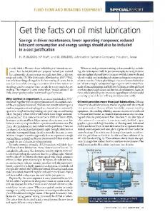
Consider a body consisting of a solid disk with distributed parameters as depicted in Fig. 1. Let N be the number of concentric annular layers in the system and ai−1 and ai the inner and outer radii of the ith annulus each with density i, thickness hi, modulus of elasticity Ei, and Poisson’s ratio i, i = 1 , . . . , N 关see Eqs. 共A3兲 and 共A4兲兴. Assume that the disk is subjected to nondecaying tangential and radial vibrations in one of its natural modes and that vibration is absent along the z-axis. In polar coordinates 共with x = r cos and y = r sin 兲 consider the equilibrium position 共x , y兲 ⬅ P共r , 兲 of a vibrating particle 共vibrating mass element兲 in the ith layer of the body, ai−1 艋 r 艋 ai. Let rˆ be the unit vector in the direction of increasing r, so that the position vector of the equilibrium point P共r , 兲 is r = rrˆ . Consider the orthogonal unit vector ˆ = 共r / 兲 / 兩r / 兩. Let viˆ + uirˆ represent the displacement from the equilibrium position of the vibrating particle in the ith layer. For simplicity we suppress the subscript i if no confusion is expected. The position vector of the vibrating particle is thus
56 57 58 59 60 61 62 63 64 65
BF =
22 23 24 25 26 27 28 29 30 31 32 33 34 35 36 37 38 39 40 41 42 43 44 45 46 47 48 49 50 51 52 53 54
Angular rate of the vibrating pattern . Angular rate of the vibrating body
共1兲
The constant of proportionality BF is known as “Bryan’s factor.” Estimates based on Bryan’s effect were used to demonstrate that the resonance of liquid surface vibrations in a wineglass2 was predictable using a membrane model.3 We have been investigating Bryan’s effect in various solid and fluid-filled symmetric objects that rotate at a constant rate which is much smaller than the lowest frequency of vibration of the structure. To understand Bryan’s effect, investigations were conducted starting with a slowly rotating and vibrating 共isotropic solid兲 disc and then progressing to a cylinder and a sphere. Each of these investigations yielded identical 共up to constant coefficients兲 ordinary differential equations that can be used to explain Bryan’s effect. In this paper we demonstrate how these differential equations are derived, how Bryan’s factor can be calculated, and how Bryan’s effect can be predicted. In 1988, Zhuravlev and Klimov4 investigated Bryan’s effect for an isotropic, spherically symmetric body rotating in three dimensions. Among other results, they demonstrated that Bryan’s effect depends on the vibration mode. Bryan’s effect has numerous navigational applications.5 Bryan’s factor is used to calibrate vibrating cylindrical gyroscopes. In Ref. 5 a thin cylindrical shell was considered for both high and low rotational rates. Apart from navigational applications, the theory presented in Ref. 6 could be useful in understanding the dynamics of pulsating stars and earthquakes. We will discuss Bryan’s effect for a symmetrically distributed annular disc, where both radial and tangential vibrations are considered, and ignore axial vibrations. The theory is readily adapted to an isotropic solid cylinder 共or sphere兲 in the form of concentric cylindrical 共or spherical兲 bodies where some of the layers are fluids. 1
Am. J. Phys. 77 共5兲, May 2009
http://aapt.org/ajp
ˆ. R = 共r + u兲rˆ + v
71 72 73 74
76 77 78 79 80 81 82 83 84
共3兲 85
ˆ is the unit vector in the direction of the posiwhere kˆ = rˆ ⫻ tive Z-axis. We assume that the angular rate of rotation ⍀ is substantially smaller than the lowest vibration frequency of the system. Consequently, we will neglect centrifugal effects and all other terms of O共⍀2兲. An observer in the Oxyz coordinate system will measure ˆ to be constants. Hence this observer the unit vectors rˆ and will use Eq. 共2兲 to calculate the velocity V* of the vibrating particle in the rotating framework Oxyz, by differentiating R, ˆ as constants: treating rˆ and © 2009 American Association of Physics Teachers
70
共2兲 75
Now consider an inertial coordinate system OXYZ with its origin O at the center of the disc, where the X-, Y-, Z-axes initially correspond to the x-, y-, z-axes, respectively.7 Assume that the disk rotates about the Z-axis with a small constant angular frequency ⍀. Consequently, the z-axis and the Z-axis are identical, but the angle between the X-axis 共which is fixed in space兲 and the x-axis 共which is fixed with respect to the geometry of the disc兲 increases at a rate ⍀. The angular velocity of the disk is thus ⍀ = ⍀kˆ ,
66 67 68 69
1
86 87 88 89 90 91 92 93 94 95
shear stress, respectively, and ⑀ and ␥ stand for tensile strain, 130 and shear strain respectively. According to Eqs. 共C3兲 and 131 132 共C4兲, the stresses are Ei 共⑀r,i + i⑀,i兲, 1 − 2i
r,i =
,i =
Ei 共⑀,i + i⑀r,i兲, 1 − 2i 共9兲 133
r,i = Fig. 1. Coordinate system for the annular disk consisting of various concentric annular layers of varying thickness.
V* =
96 97 98 99 100 101 102 103 104 105 106 107 108
冏 冏 dR dt
rˆ ,ˆ =const
ˆ. = u˙rˆ + v˙
共4兲
An observer in the OXYZ coordinate system will note that ˆ is continuously the direction of the unit vectors rˆ and changing. Hence, they are not constant vectors in the OXYZ frame. In addition to the velocity V*, we must take into account the velocity imparted by rotation. Recall that a particle moving along a circular path of radius r and with angular rotation rate has a tangential speed r. Hence, a particle with angular velocity ⍀ and position vector R has a velocity component given by the cross product ⍀ ⫻ R. Consequently, the “true velocity” of the vibrating particle as observed from within the fixed frame OXYZ is V = V* + ⍀ ⫻ R
109
共5兲
ˆ. =共u˙ − ⍀v兲rˆ + 关v˙ + ⍀共r + u兲兴
110
134
Strains may be calculated as follows 共see, for instance, Ref. 135 136 10 or 11兲:
⑀r,i =
ui , r
␥r,i =
冉
冊
⑀,i =
1 vi + ui , r
共11兲
冉
冊
共12兲
vi 1 ui + − vi . r r
137
138
Problem 1. Substitute Eqs. 共9兲 and 共10兲 into Eq. 共8兲, and 139 140 then use Eqs. 共11兲 and 共12兲 to obtain N
Ep =
1 E ih i 兺 2 i=1 1 − 2i + +
冋冉
冕 冕 再冋 册 2
0
1 vi + ui r
冋
冊册
ai
ai−1
2
+
冉
ui r
2
冉
2i ui vi + ui r r
1 − i vi 1 ui + − vi 2 r r
冊册 冎
141
冊
142
2
r dr d .
共13兲
143
共6兲
Spiegel provides a detailed discussion of the derivation of Eq. 共5兲.
113
III. KINETIC AND POTENTIAL ENERGY
114 115
If we use Eq. 共6兲, the kinetic energy Ek of the system of particles forming the concentric annular layers is given by N
1 E k = 兺 ih i 2 i=1
116
N
冕 冕 2
0
ai
Vi · Vir dr d
共7a兲
ai−1
冕 冕 2
ai
117
1 兺 ih i 2 i=1
118
+ 2⍀共uiv˙ i − u˙ivi兲 + 2⍀v˙ ir兴r dr d .
⬇
0
关共u˙2i + v˙ 2i 兲
ai−1
共7b兲
When a spring is stretched, the elastic forces involved can do work. Elastic forces are present when an “elastic” body vibrates, and so it is necessary to introduce some of the theory of elasticity to calculate the potential energy of the system of particles forming the concentric annular layers. A short discussion of elasticity is given in Appendixes A–C. According to Eq. 共B4兲, the potential energy E p of a system of concentric annular layers is given by N
1 E p = 兺 hi 2 i=1
127
冕 冕 2
0
ai
关r,i⑀r,i + ,i⑀,i
ai−1
+ r,i␥r,i兴r dr d ,
128 129
共10兲
7
111 112
119 120 121 122 123 124 125 126
Ei ␥r,i . 2共1 + i兲
共8兲
where the symbols and stand for the tensile stress and 2
Am. J. Phys., Vol. 77, No. 5, May 2009
IV. GYROSCOPIC EFFECTS IN DISTRIBUTED BODIES
144 145
Equations of motion for the vibrating particle in the ith body can be obtained by using Eqs. 共9兲–共12兲, and the equations of motion discussed by Redwood.8 The resulting equations consist of two coupled partial differential equations involving terms such as 2ui / t2, 共2vi / t2兲, 共ui / r兲, vi / , 2ui / r. Solving this coupled system of partial differential equations is a nontrivial problem that involves finding, for each i, two families of eigenfunctions Ui,m共r兲 and Vi,m共r兲, m = 2 , 3 , 4 , . . . . The number m is the vibration mode number or the circumferential wave number. We will not attempt to determine these eigenfunctions here, and we leave this determination for a future paper. We will assume that we can calculate these eigenfunctions and that we can 共for each mode of vibration兲 express the displacements ui and vi of a vibrating particle in the ith layer of the body as follows:
146 147 148 149 150 151 152 153 154 155 156 157 158 159 160
ui共r, ,t兲 = Ui共r兲关C共t兲cos m + S共t兲sin m兴,
共14兲 161
vi共r, ,t兲 = Vi共r兲关C共t兲sin m − S共t兲cos m兴,
共15兲 162
m = 2 , 3 , 4 , . . ., where the functions C共t兲 and S共t兲 are to be determined. Here, for simplicity, we have suppressed the mode number on the eigenfunctions, that is, Ui共r兲 = Ui,m共r兲 and Vi共r兲 = Vi,m共r兲. It is left as an exercise to determine the nature of the functions C共t兲 and S共t兲. Problem 2. Substitute Eqs. 共14兲 and 共15兲 into Eqs. 共7b兲 and 共13兲. Simplification of these expressions involves a long Joubert, Shatalov, and Fay
2
163 164 165 166 167 168 169
170
algebraic calculation. The use of a computer algebra system 171 such as Mathematica or Maple yields ˙ 2 + S˙2兲 + 2⍀I 共C ˙ S − CS˙兲兴 Ek = 关I0共C 1
172 173
and E p = I2共C + S 兲, N
1 I 0 = 兺 h i i 2 i=1 N
I 1 = 兺 h i i
177 178
i=1
冕
冕
ai
共19兲
ai−1
冕
Ui + mVi r
ai
ai−1
冊
再
2
+
共Ui⬘兲2 + 2iUi⬘
冉
Ui + mVi r
1 − i mUi + Vi Vi⬘ − 2 r
冊冎 2
185 186
− 共C + S 兲I2兴. 2
2
共21兲
冉 冊
共22兲
冉 冊
共23兲
d L L = 0, − dt C C ˙ and
L d L = 0. − dt S˙ S
189 190
Equations 共22兲 and 共23兲 yield
191
¨ + 2⍀S˙ + 2C = 0 C
共24兲
˙ + 2S = 0, S¨ − 2⍀C
共25兲
192
and
193 194
respectively, where, for the mth mode of vibration −1ⱕ=
195 196
I1 ⱕ 1, I0
共26兲
and is given by
=
197
冑
I2 . I0
共27兲
198
B. Bryan’s factor
199 200
We now show that is an eigenvalue of the vibrating system and that in Eq. 共26兲 is Bryan’s factor BF in Eq. 共1兲. 3
206
Z共t兲 = r共t兲ei共t兲 ,
共30兲 207
Am. J. Phys., Vol. 77, No. 5, May 2009
r¨ + 2i共a − ⍀兲r˙ + 共2⍀a − a2 + 2兲r = 0.
共31兲 209
共32兲 213 214
␥ = 冑2 + 2⍀2
共33兲 215
is an eigenvalue of the vibrating system with eigenfrequency 216 of vibration f = ␥ / 2. According to the assumption made 217 218 shortly after Eq. 共3兲, ⍀ Ⰶ f. Consequently,
␥ ⬇ ,
The vibration of the mth mode is governed by Lagrange’s equations of motion:
187 188
共20兲
˙ 2 + S˙2兲 − 2⍀I 共CS˙ − C˙S兲 ˙ ,S˙兲 = E − E = 关I 共C L共C,S,C k p 0 1
184
If we write Z in polar form
where
r dr.
The Lagrangian follows from Eqs. 共16兲 and 共17兲:
183
共29兲 205
r¨ + ␥2r = 0,
A. Lagrange’s equations
182
Z¨ − i共2⍀兲Z˙ + 2Z = 0.
If we choose a = ⍀, the coefficient of r˙ is eliminated in Eq. 210 共31兲, and we obtain the differential equation of a harmonic 211 212 oscillator:
180
181
204
and assume that 共t兲 has the linear form 共t兲 = at, we obtain 208
UiVir dr,
N
冉
共18兲
ai
1 E ih i I2 = 兺 2 i=1 1 − 2i +
共U2i + V2i 兲r dr,
ai−1
and
179
共17兲
2
where
176
共28兲 203
Z = C + iS to obtain the single equation
2
174 175
共16兲
To interpret what Eqs. 共24兲 and 共25兲 represent we combine 201 the two equations by considering the complex function 202
共34兲 219
and so is an eigenvalue of the vibrating system. Equations 220 221 共24兲 and 共25兲 can now be viewed in the form Z共t兲 = r共t兲ei⍀t .
共35兲 222
Equation 共35兲 shows that Eqs. 共24兲 and 共25兲 represent a “vector” in the complex plane with its magnitude varying like a harmonic oscillator and its position varying at a rate proportional to the constant, small rotation rate ⍀ of the isotropic body. Hence, according to Eq. 共1兲, Bryan’s factor BF =
⍀ ⍀
= .
共36兲
Consequently, if a gyroscope based on Bryan’s effect12 is to be calibrated, then, without conducting lengthy experiments, Bryan’s factor can be calculated from Eq. 共26兲 once the eigenfunctions of Eqs. 共14兲 and 共15兲 are known. Equations 共18兲–共20兲, 共26兲, and 共27兲 show that for the mth mode of vibration, Bryan’s factor and the eigenfrequency of vibration depend on physical properties such as the density and geometrical properties such as thickness. The eigenfrequency also depends on elastic properties such as Young’s modulus and Poisson’s ratio. Equation 共35兲 defines a precessing wave. The rotating vibration pattern lags behind the position of the static vibration pattern if ⬍ 0 and precedes the position of the static vibration pattern if ⬎ 0. A calculation of for a liquid filled wineglass3 and m = 2 reveals to be negative. Hence, the rotating vibration pattern should lag behind the static vibration pattern for the wineglass. We note that Eqs. 共24兲 and 共25兲 are obtained with appropriate values of I0, I1, and I2 for isotropic cylindrical or spherical distributed bodies. The definite integrals I0, I1, and I2 are far more complicated for a cylinder and sphere. Joubert, Shatalov, and Fay
3
223 224 225 226 227
228 229 230 231 232 233 234 235 236 237 238 239 240 241 242 243 244 245 246 247 248 249
250
Problem 3. Show that to a good approximation
251
C共t兲 = cos ⍀t共A cos t + B sin t兲,
共37兲
252
S共t兲 = sin ⍀t共A cos t + B sin t兲
共38兲
共where A and B are arbitrary constants兲 by solving Eq. 共32兲 for r共t兲, substituting into Eq. 共35兲, equating real and imagi255 nary parts, and then using Eq. 共34兲. 256 Problem 4. Use the Lagrangian L as given by Eq. 共21兲 and 257 include viscous damping by introducing Rayleigh’s dissipa˙ 2 + sS˙2兲 / 2 into Lagrange’s equations 258 tion function F = 共cC 259 共see Ref. 9兲. Assume weak, isotropic, viscous damping, that 260 is, c = s = D, with the damping factor ␦ = D / 共2I0兲 much 261 smaller than the lowest eigenfrequency of the vibrating sys262 tem. Conclude that the introduction of light, viscous, isotro263 pic damping into the considerations does not alter the fact 264 that the damped vibrating pattern rotates at a rate ⍀ in the 265 Oxyz plane, where is given by Eq. 共26兲. See Ref. 6 for 266 details. 253 254
267
V. CONCLUSION
268 269 270 271 272 273 274 275 276 277 278 279 280 281 282 283 284 285 286 287 288 289 290 291 292 293 294
By using standard concepts of physics such as kinetic energy, potential energy, and Lagrange’s equations, we have demonstrated how Bryan’s effect for a composite disk that is rotating slowly in space can be predicted and Bryan’s factor can be calculated. These considerations also demonstrated that Bryan’s factor depends on properties such as the density and the thickness of the disk and that the eigenfrequency of vibration of the disk also depends on elastic properties such as Young’s modulus and Poisson’s ratio. We can now better understand the operation and calibration of the hemispherical resonator gyroscope of Loper and Lynch.12 Roughly speaking, suppose that a vibrating hemisphere is fixed to a vehicle 共such as a space shuttle or submarine兲 moving through three-dimensional space and that a sensor inside the vehicle observes the position of a node of the fundamental vibration of the hemisphere 共such vibrations can be observed in the excellent holographic interferograms of a vibrating wineglass in Ref. 13兲. Suppose the vehicle undergoes a slow rate of rotation ⍀ with respect to the space through which it is moving and that this rotation rate is too small for the human vestibular system to observe. The sensor will register that the node rotates away from its original position. From observations within the vehicle the rotation rate ␣ of the node can be calculated and, using Bryan’s factor for the fundamental mode of vibration, the rate of rotation of the vehicle ⍀ = ␣ / with respect to the space through which it is moving can be calculated.
Fig. 2. Elastic blocks undergoing tensile deformation 共left block兲 and shear deformation 共right block兲.
APPENDIX A: ELASTIC CONSTANTS
300
A body will deform when stretching and/or twisting forces are applied to it. We consider as a first approximation a perfectly elastic body that returns to its original form after stretching and/or twisting forces are removed from it. Consider a length ᐉ of an elastic block 共Fig. 2兲 with crosssectional area A that is subjected to a stretching force F⬜ 共normal to the area A兲 causing the side length to increase from ᐉ to ᐉ + ⌬ᐉ. The tensile stress of the elastic body is given by
301 302 303 304 305 306 307 308 309
=
F⬜ , A
共A1兲
and the tensile strain ⑀ is given by
⑀=
⌬ᐉ . ᐉ
311
共A2兲
E=
tensile stress = . tensile strain ⑀
共A3兲
If a length of elastic body is stretched from length ᐉ to ᐉ + ⌬ᐉ, its transverse dimensions 共its height or breadth兲 t decreases from t to t + ⌬t 共here ⌬t ⬍ 0兲. Hence, both longitudinal strain ⌬ᐉ / ᐉ and transverse strain ⌬t / t are present simultaneously. 共For isotropic substances transverse strain is the same for any transverse dimensions such as height, breadth, or diameter.兲 Poisson’s ratio is defined as the positive dimensionless constant
=−
冉
冊 冉 冊
longitudinal strain ⌬ᐉ/ᐉ =− . transverse strain ⌬t/t
共A4兲
Suppose that an elastic block 共Fig. 2兲 is subjected to a shearing or twisting force F储 共parallel to the area A兲 that twists the body through a small angle 共in Fig. 2, ⬇ ⌬s / ᐉ兲. The shear stress of the body is given by
=
F储 , A
共A5兲
␥ = . ACKNOWLEDGMENTS
296 297 298 299
The authors would like to thank the Tshwane University of Technology, the National Research Foundation of South Africa 共NRF Grant reference No. ICD200607110000607兲, and the South African CSIR for supporting this work. 4
Am. J. Phys., Vol. 77, No. 5, May 2009
312
Young’s modulus 共or the modulus of elasticity兲 E is given by 313
and the shear strain ␥ is given by 295
310
315 316 317 318 319 320 321 322
323 324 325 326 327
328 329
共A6兲 330
The shear modulus G is given by G=
314
shear stress = . shear strain ␥
331
共A7兲
It can be shown 共see Ref. 10兲 that Joubert, Shatalov, and Fay
332 333
4
there is a shear stress r parallel to the r-plane. Suppose that the volume element dV is subjected to a shear force rrddr which produces a shear extension ␥rdz. According to the shear version of Eq. 共B1b兲, the work done by the shear force to produce this shear extension is
361 362 363 364 365
1 1 共shear force兲关shear extension兴 = 共rrddr兲关␥rdz兴. 2 2 共B3兲 366 There are two similar expressions for the work done by the radial and tangential tensile forces. We sum the three expressions to obtain the total potential 共or strain兲 energy of the volume element: 1 dW = 共r⑀r + ⑀ + r␥r兲rdrddz. 2
Fig. 3. Volume element dV = rdrddz in polar coordinates before deformation 共thick lines兲 and after deformation 共thin lines兲.
G=
334 335
␥=
2共1 + 兲 . E
共A9兲
Equations 共A3兲 and 共A7兲 are forms of Hooke’s law. For instance, from Eq. 共A3兲, we deduce the well known law for elastic elongation w 共usually referred to as Hooke’s law兲:
371
APPENDIX C: SUPERPOSITION
372
Consider the tensile and shear strains of the volume element dV of Eq. 共B2兲. A radial 共tangential兲 strain r / E 共 / E兲 is accompanied by a lateral contraction per unit length or a lateral strain in the tangential 共radial兲 direction −r / E 共− / E兲, where is Poisson’s ratio. Shear stresses do not cause lateral stresses. Hence, by superposition, the net strains are
373 374
1 ⑀r = 共r − 兲, E
共A10兲
F = kw,
340 341
共A8兲
and so
336 337 338 339
E , 2共1 + 兲
共B4兲
367 368 369 370
␥ r =
with k = AE / ᐉ, w = ⌬ᐉ, and F = F⬜.
1 ⑀ = 共 − r兲, E
1 2共1 + 兲 r = r . G E
共C1兲 共C2兲
375 376 377 378 379
380
381
Problem 5. Solve Eq. 共C1兲 simultaneously and manipulate 382 Eq. 共C2兲 to show that stresses are given in terms of strains as 383 342 343 344 345 346 347
APPENDIX B: POTENTIAL ENERGY When a tensile extension w occurs, work has been done by the force F = F⬜. This work is stored as potential energy. According to the tensile form of Hooke’s law given by Eq. 共A10兲, this tensile potential energy 共also called tensile strain energy兲 is given by
冕
u
0
F dw = k
冕
u
0
1 1 w dw = 共kw兲关w兴 = 共F⬜兲 ⫻ 关⌬ᐉ兴 2 2
349
1 = 共tensile force兲 ⫻ 关tensile extension兴. 共B1b兲 2
350 351 352 353
A similar formula holds for shear potential energy. In an elastic solid disk with distributed parameters as depicted in Fig. 1, suppose that we have an elastic volume element dV at the point P,
355 356 357 358 359 360
共B2兲
as depicted in Fig. 3. Here the thickness of the disk at point P is h = 兰h0dz. Tensile stresses r in the radial direction and in the tangential direction exist, but there are no tensile stresses on faces 共areas兲 parallel to the area rddr in the r-plane. There are no shear stresses parallel to the areas drdz or rddz, but 5
Am. J. Phys., Vol. 77, No. 5, May 2009
r =
E ␥ r . 2共1 + 兲
=
E 共⑀ + ⑀r兲, 1 − 2
共C3兲 共C4兲
Electronic mail:
[email protected] Permanent address: CSIR, Material Science and Manufacturing, Sensor Science and Technology, P. O. Box 395, Pretoria 0001, South Africa. 1 G. H. Bryan, “On the beats in the vibrations of a revolving cylinder or bell,” Proc. Cambridge Philos. Soc. Math. Phys. Sci. 7, 101–114 共1890兲. 2 R. E. Apfel, “ ‘Whispering waves’ in a wineglass,” Am. J. Phys. 53共11兲, 1070–1073 共1985兲. 3 S. V. Joubert, T. H. Fay, and E. L. Voges, “A storm in a wineglass,” Am. J. Phys. 75共7兲, 647–651 共2007兲. 4 V. Zhuravlev and D. Klimov, Applied Methods in the Theory of Oscillations 共Nauka, Moscow, 1988兲 共in Russian兲. 5 P. W. Loveday and C. A. Rogers, “Free vibrations of elastically supported thin cylinders including gyroscopic effects,” J. Sound Vib. 217共3兲, 547– 562 共1998兲. 6 M. Y. Shatalov, S. V. Joubert, C. E. Coetzee, and I. A. Fedotov, “Free vibration of rotating hollow spheres containing acoustic media,” J. Sound Vib., to be published. 7 M. R. Spiegel, Theoretical Mechanics 共McGraw-Hill, New York, 1967兲, pp. 148, 284. 8 M. Redwood, Mechanical Waveguides 共Pergamon, Oxford, 1960兲, pp. 9, 268. 9 H. Goldstein, C. Poole, and J. Safko, Classical Mechanics, 3rd ed. 共Addison-Wesley, Reading, MA, 2001兲, pp. 21, 23.
b兲
共B1a兲
dV = drdzrd = rdrddz,
E 共⑀r + ⑀兲, 1 − 2
a兲
348
354
r =
Joubert, Shatalov, and Fay
5
384
385
386 387 388 389 390 391 392 393 394 395 396 397 398 399 400 AQ: 401 #1 402 403 404 405 406 407 408
409 410 411 412
S. P. Timoshenko and J. N. Goodier, Theory of Elasticity 共McGraw-Hill, Auckland, 1970兲, pp. 8–11, 75–77, 244–245. 11 P. P. Benham and R. J. Crawford, Mechanics of Engineering Materials 共Longman Scientific, Harlow, 1991兲, p. 381. 10
6
Am. J. Phys., Vol. 77, No. 5, May 2009
12
E. J. Loper, Jr. and D. D. Lynch, “Hemispherical resonator gyroscope,” U.S. Patent No. 4,951,508. 13 T. D. Rossing, “Acoustics of the glass harmonica,” J. Acoust. Soc. Am. 95 共2兲, 1106–1111 共1994兲.
Joubert, Shatalov, and Fay
6
413 414 415 416
NOT FOR PRINT!
FOR REVIEW BY AUTHOR
AUTHOR QUERIES — 006905AJP
#1
Au: Please update Ref. 6, if possible.
NOT FOR PRINT!