Rotor Performance Enhancement and Vibration Reduction in Presence of Dynamic Stall Using Actively Controlled Flaps Li Liu Postdoctoral Scholar
[email protected]
Peretz P. Friedmann Insung Kim Franc¸ois-Xavier Bagnoud Ph.D. Candidate Professor of Aerospace Engineering
[email protected]
[email protected]
Dennis S. Bernstein Professor
[email protected]
Department of Aerospace Engineering University of Michigan, Ann Arbor, Michigan
Abstract A computational study of helicopter vibration and rotor shaft power reduction is conducted using activelycontrolled trailing-edge flaps (ACFs), implemented in both single and dual flap configurations. Simultaneous vibration reduction and performance enhancement is demonstrated under level flight condition at high advance ratios, where dynamic stall effects are significant. Power reduction is achieved using the adaptive Higher Harmonic Control (HHC) algorithm in closed loop, with 2-5/rev flap control harmonics. This approach is compared with an off-line, nonlinear optimizer available in MATLAB, and favorable comparisons are obtained. A parametric study of flap spanwise location is also conducted to determine its optimal location for power reduction. The effectiveness of the ACF approach for power as well as simultaneous vibration and power reduction is also compared with conventional individual blade control (IBC) approach. Rotor power reduction and simultaneous reduction of vibration and power are shown to be larger at higher rotor thrust and advance ratio. Finally, the effect of active flap on dynamic stall is examined to determine the mechanisms of rotor power reduction. The simulation results clearly demonstrate the potential of the ACF system for power reduction as well as simultaneous vibration and power reduction.
Nomenclature c cc CT D fb (.) ft (.) FHX4 , FHY 4 , FHZ4 MHX4 , MHY 4 , MHZ4 J
Blade chord Flap chord Rotor thrust coefficient Matrix defined as TT QT + R Blade equations of motion Trim equations 4/rev hub shears, nondimensionalized by Mb Ω2 R 4/rev hub moments, nondimensionalized by Mb Ω2 R2 Quadratic-form objective function to be minimized
Presented at the American Helicopter Society 62nd Annual Forum, Phoenix, AZ, June 9-11, 2006. 1
Mb mc MHz1 Nb PR qt qti Q R R Rt T uk uk,opt xc zk αR δf ∆Cd,flap δNc , δNs βp γ µ ωF , ωL , ωT Ω ψ φR θ0 , θ1c , θ1s θ0t θtw σ
Blade mass Flap mass per unit length, nondimensionalized by Mb /R Yawing moment about rotor hub Number of rotor blades Rotor shaft power, nondimensionalized by Mb Ω3 R2 Vector of trim variables Vector of trim variables at i-th control step Weighting matrix for objectives to be minimized Weighting matrix on control input Rotor blade radius Trim residuals vector Sensitivity, transfer matrix between control inputs and objective function Control input vector, kth control step Optimum value of control input vector Spanwise location of center of control surface Objective vector, kth control step Rotor shaft angle of attack Flap deflection angle Additional drag due to flap deflection N/rev cosine and sine amplitude of δ Blade precone angle Lock number Helicopter advance ratio Blade flap, lead-lag and torsional natural frequencies Rotor angular speed Rotor azimuth angle Lateral roll angle Collective and cyclic pitch components Tail rotor collective pitch Built-in twist angle Rotor solidity
Introduction and Background
Specifications for noise and vibration levels in rotorcraft are continuously increasing in stringency, thus motivating research related to active noise and vibration reduction. Desirable vibration levels have been identified to be below 0.05g to provide passengers with “jet smooth” ride (Ref. 1). A number of active control techniques have emerged for effective vibration reduction (Refs. 1, 2), as illustrated schematically in Fig. 1. These approaches generally fall into one of two categories: (a) active control approaches aimed at reducing vibrations in the rotor before they propagate into the fuselage, and (b) active control approaches
2
implemented in the fuselage using an approach known as active control of structural response (ACSR). Within the first category of active control, where the primary objective is to reduce vibrations in the rotor, two approaches to physical realization have emerged. These are (1) higher harmonic control (HHC) where the blades are activated by introducing pitch commands via the swashplate, and (2) individual blade control (IBC) where each blade can be controlled independently in the rotating frame. Several implementations of are available: (i) the conventional or earliest implementation based on pitch actuation at the blade root
IBC
in the rotating system, (ii) actively controlled partial-span trailing-edge flaps, and (iii) the active-twist rotor where the entire blade is twisted by piezoelectric fiber embedded in the blade. Additional descriptions of these approaches can be found in Refs. 1 and 2. Among these approaches,
HHC
and
IBC
were developed earlier and have been tested extensively in the
wind tunnels as well as flight tests. Excellent vibration reduction of more than 80% has been demonstrated using these approaches. Subsequently, these approaches have also been considered for noise control, particularly in the blade vortex interaction (BVI) flight regime. Reduction of noise levels by 4-10 dB, under
BVI
conditions, has been demonstrated in wind tunnel tests, on various helicopter configurations (Refs. 3–5). It is important to note that these active control approaches have employed primarily what is known as the conventional
HHC
algorithm (alternatively termed the multicyclic algorithm) in rotorcraft community for
vibration reduction (Refs. 1, 2, 6, 7). More recently, actively controlled flaps (ACFs) have emerged as an efficient means of the active control of vibration due to these studies the
BVI
ACF
as well as the alleviation of dynamic stall induced vibrations (Refs. 2, 8–15). In
system was implemented in both single and dual flap configurations and vibration
reduction comparable to that achieved with
HHC
or conventional
effects on helicopter airworthiness. Furthermore, the
ACF
IBC
was demonstrated without adverse
system has significantly lower actuation power
requirement, when compared to the blade root actuation approaches (Ref. 2). A piezoelectrically actuated ACF
system is also more compact and has less weight than the conventional root actuation approaches,
3
which have employed hydraulic actuators. Wind tunnel tests have also shown the feasibility of the ACF for vibration reduction (Refs. 15,16). During the Smart Material Actuated Rotor Technology (SMART) program conducted by Boeing (Refs. 17,18), a full scale piezoelectrically actuated flap system for vibration and noise control for a five-bladed bearingless MD-900 rotor has been tested on a whirl tower to demonstrate control effectiveness. In Europe, a full scale BK117 with three actively controlled, piezoelectrically actuated flaps per blade has been flight tested by Eurocopter Germany in the open loop mode on September 6, 2005 and additional flight tests, including closed loop tests, are currently in progress (Ref. 19). In Refs. 11, 12, the effectiveness of ACF system to reduce the vibrations in the high advance ratio flight regime, where dynamic stall effects are known to be important, was studied by Depailler and Friedmann. The simulation indicated that
ACF
was successful in alleviating dynamic stall induced vibrations, thus demon-
strating the capability of the ACF systems to reduce vibrations due to multiple sources. Recently, a comprehensive helicopter simulation was developed using a unified approach for the prediction and active control of vibratory loads and blade-vortex interaction noise (Refs. 20, 21). Considerable potential for active noise reduction and simultaneous vibration and noise reduction have been demonstrated using actively controlled flaps with 2-5/rev components on a rotor resembling the MBB BO-105 hingeless rotor (Ref. 21). The capability of the ACF system has also been demonstrated using a bearingless rotor configuration resembling the MD-900 rotor in Ref. 22. Despite the vibration and noise reduction demonstrated in experiments and numerical simulations, these active control techniques are still in preliminary flight test stages (Ref. 23). Concerns associated with cost of implementation, interference with the primary flight controls, and the potential power penalties for operating the helicopter have prevented the actual implementation of such devices on a production helicopter. Clearly further study of such active control devices is needed, so as to reap the largest potential benefit on the sizeable cost associated with installing such active control systems in a production helicopter. One of the most important considerations when deploying active noise and vibration control systems is the prevention of any
4
performance penalty that can be caused by the system. Equally important is the potential for performance enhancement with an active control device which would provide justification for compensating for the cost of the system. Preliminary experimental studies were conducted by Ham on an
IBC
system to consider a wide range
of applications, including stall alleviation and performance enhancement (Refs. 24, 25). These early studies were quite simple and inconclusive; however, these indicated the potential of the IBC approach. A wind tunnel study by Shaw et. al. (Ref. 26), which was intended primarily to demonstrate the effectiveness of
HHC
system for vibration reduction, also provided a preliminary assessment of the system for performance enhancement. The test was conducted on a scaled three-bladed CH-47D rotor, at two cruise airspeed conditions of 135 knots and 160 knots (µ ≈ 0.30 and 0.35), respectively. Pure 2/rev HHC inputs in the rotating system with 2◦ amplitude were used for performance enhancement, and the optimal phase angle was determined experimentally, by trial and error. It was found that the power required in trim was reduced substantially by 6% at 135 knots and 4% at 160 knots. In another study, full-scale wind tunnel tests of a rotor were conducted at NASA Ames in the 40 × 80 foot wind tunnel (Refs. 4, 27). An
MBB
IBC
BO-105
system was
tested in the open-loop for vibration and noise reduction as well as rotor power reduction. Rotor power reductions of up to 7% were demonstrated using 2/rev
IBC
at advance ratios of 0.40 and 0.45, however, no
power reduction could be achieved at advance ratio of 0.30. An analytical study conducted by Nguyen and Chopra (Ref. 28) examined the effects of
HHC
on a
scaled three-bladed rotor similar to the one tested in Ref. 26. A power reduction of 3.8% was obtained using 2/rev
HHC
inputs with 2◦ amplitude. Cheng and Celi (Ref. 29) performed a computational study of power
reduction using 2/rev
HHC
inputs. The rotor model used was fairly simple, with rigid blade dynamics and
a dynamic inflow model. The study noted that rotor power reductions were possible when using properly phased open-loop
HHC
input, at an advance ratio of µ = 0.3. Reference 29 was based on quasisteady,
table look-up aerodynamics and a nonlinear drag model, and it was emphasized that power reductions could
5
only be obtained by simulation when a nonlinear drag model was used. A subsequent study by the same authors used numerical optimization techniques to determine the optimal 2/rev input, and included a free wake model (Ref. 30). The predicted power reduction was almost eliminated when the free wake model was added. Performance enhancement using the ACF approach has only been attempted in a few studies thus far. A model rotor equipped with cam operated trailing edge flaps was tested in wind tunnel by Straub (Ref. 31). Effect on rotor performance with 2/rev flap actuation was evaluated at advance ratios of 0.25 and 0.30, but the results were considered inconclusive due to issues associated with the accuracy of the measurements obtained during the test. A preliminary computational study on rotor power reduction for a rotor resembling the MBB BO-105 was conducted in Ref. 32. In this study a single flap configuration with deflections limited to 4◦ degrees was examined in the open loop mode, under
BVI
conditions at µ = 0.15. It was found that
power reduction could only be obtained when the fundamental torsional frequency of the rotor was reduced from the actual value of the MBB BO-105 rotor to a lower value of 2.5/rev. When using an
ACF
for vibration or noise reduction the deflections of the flap increase the drag of the
blade and therefore vibration and noise reduction may be accompanied by a performance penalty. The fundamental question is therefore whether it is possible to use the ACF system without incurring an unacceptable power penalty. Motivated by this desire the overall objective of the paper is to examine simultaneous vibration reduction and performance enhancement using the the
ACF
ACF
based approach. Rotor power reduction using
approach in closed loop control will be emphasized. Based on the concise review of previous re-
search provided in this introduction on rotor power reduction, the rotor power reduction problem at advance ratios of higher than µ = 0.35 will be considered, since this is of primary interest in cruise condition. While the noise aspect associated with this problem is also of interest, the noise emissions at such advance ratios are typically dominated by high speed impulsive (HSI) noise (Ref. 33) and this problem is computationally very intensive and therefore will be considered in follow-on research. The specific objectives of the paper
6
are summarized below:
• assess the potential for rotor power reduction using the
ACF
system by applying the
HHC
control
algorithm; • examine the mutual interaction between power reduction and vibration reduction, and explore the potential of simultaneous power and vibration reduction using the ACF system; • determine the sensitivity of power reduction to flap spanwise locations; • compare the effectiveness for power reduction using the
ACF
approach with conventional
IBC
ap-
proach; • explore the effect of flight conditions such as rotor thrust and forward flight speed on the power reduction capability of the ACF system; • conduct a study of power reduction, vibration reduction as well as simultaneous reduction using offline nonlinear optimizers, and compare the results with those obtained using the HHC algorithm.
Achieving reduced vibration or noise levels without undue performance penalty is central for the practical implementation of the ACF
ACF
system; and it has a key role governing the feasibility of implementing an
system in a practical setting.
Mathematical Model
The present study is based on a comprehensive rotorcraft aeroelastic simulation tool that accounts for the effects of dynamic stall at high advance ratios, as described in detail in Refs. 11,12. The power reduction studies conducted in the present research will be carried out at advance ratios of 0.35 or higher, where the dynamic stall effects are important. The fundamental ingredients of the aeroelastic model are concisely summarized in the following subsections. Additional details can be found in Ref. 34.
7
Structural dynamic model The structural dynamic model consists of an isotropic hingeless rotor blade, cantilevered at the hub and having fully coupled flap-lag-torsional dynamics including nonlinearities due to moderate blade deflections (Ref. 8). The aeroelastic model is capable of simulating rotors with single or dual actively controlled partial span trailing edge flaps mounted on the rotating blade as depicted in Fig. 1. The equations of motion are discretized using the global Galerkin method, based upon the free vibration modes of the rotating blade. Three flapping modes, two lead-lag modes and two torsional modes are used when computing the numerical results given in the results section.
Aerodynamic model Blade sectional aerodynamic loads for attached flow are calculated using a rational function approximation (RFA) approach as described in detail in Ref. 9. The
RFA
approach is a two-dimensional, unsteady
time-domain aerodynamic theory that accounts for compressibility, variations in the oncoming velocity and a blade-flap combination. Aerodynamic cross-sectional loads consisting of lift, moment and flap-hinge moment are calculated, together with chordwise pressure distribution (Ref. 20) which may be required in acoustic calculations. Reduced flap efficiency due to three-dimensional as well as viscous effects are taken into account by using a multiplicative correction factor of 0.6 for the flap induced lift and moment. This empirical factor was chosen for the servo flap configuration as in Ref. 8. The
RFA
model for the blade-
flap combination is linked to a free wake model (Ref. 10), which produces non-uniform inflow distribution. The free wake model allows distorsion of the concentrated tip vortices due to wake self-induced velocities. The weaker, inboard vortices are also modeled using vortex sheet elements (Ref. 10). For the separated flow regime, unsteady aerodynamic loads are calculated using the ONERA dynamic stall model described by Petot (Ref. 35). The augmented aerodynamic states associated with
RFA
attached flow states and
ONERA
separated flow states are combined to produce the time-domain, state space aerodynamic model (Ref. 11). The
ONERA
dynamic stall model also accounts for nonlinear airfoil drag under dynamic conditions in
8
the stall regime. The complex compressibility effects at the blade tip region that can produce nonlinear drag due to transonic effects are not modeled in the current simulation. A linear drag model that accounts for additional drag due to flap deflection, that increases the power required for the rotor to operate, is implemented (Ref. 11). This drag model is used to estimate the additional drag due to deflections of a 0.25c servo flap, given by ∆Cd,flap = 0.001225|δ f |
(1)
Coupled trim/aeroelastic response solution The combined structural and aerodynamic equations of motion are formulated as a set of nonlinear, coupled, second order ordinary differential equations
fb (qb , q˙ b , q¨ b , xa , qt ; ψ) = 0,
(2)
where qb represents the vector of generalized coordinates, or modal participation; xa represents the vector of aerodynamic states in the RFA model, and qt represents the vector consisting of trim variables. Note that Eq. (2) contains the combined effects of various elements described earlier, including the coupled nonlinear structural model, unsteadiness, compressibility, free wake, as well as dynamic stall effects. These equations are then cast into state variable form, and integrated in the time domain using the Adams-Bashforth DE/STEP predictor-corrector algorithm. To obtain a periodic solution under steady flight condition, typically 6-10 rotor revolutions are sufficient to settle initial transients. A propulsive trim procedure is implemented in steady, level flight condition; where six equilibrium equations (three forces and three moments) are enforced. When only the steady state response of the system is considered, the trim equations can be written as
ft (qt ) = 0
9
(3)
where the trim vector qt is given by
qt = {αR , θ0 , θ1c , θ1s , θ0t , φR }T
Note that a relatively simple tail rotor model is included, which affects the pitching and yawing moment equilibrium, following the procedure outlined in Ref. 10. The trim equations are solved using an iterative procedure similar to an autopilot. The vector of trim residuals Rt at the trim variables qt is defined as
ft (qt ) = Rt
(4)
An iterative optimal control procedure is then used to reduce the value of Rt , based on the minimization of an index J that is a quadratic function of the trim residuals Rt
J = Rt T Rt
The trim variables for the i-th control step are obtained by requiring
qti = −T−1 i Rti−1 + qti−1
(5)
∂J =0 ∂ qt
(6)
where Ti is a transfer matrix describing the sensitivity of trim residuals to changes in the trim variables, given by Ti =
∂ Rti . ∂ qt
(7)
Additional details of the trim procedure can be found in Ref. 34. These trim equations are solved in a coupled manner with the aeroelastic equations of motion. Consequently, the coupled trim/aeroelastic response solution accounts for the combined effects of unsteadiness, compressibility, free wake, as well as dynamic 10
stall. Note that maintaining the same rotor trim condition is important for performance enhancement studies. The trim procedure ensures that the rotor is trimmed to the specified advance ratio and rotor thrust level CT /σ , under the same steady level flight condition. Hub vibratory loads are obtained by integrating the distributed aerodynamic and inertial loads over the blades, which are subsequently transformed to the nonrotating system and summed for all blades. Average rotor power is defined as the instantaneous power required to drive the rotor at a constant angular velocity Ω averaged over one revolution, Ω PR = 2π
Z 2π 0
−MHz1 (ψ)dψ,
(8)
where MHz1 is the total yawing moment about the hub and includes the effect of unsteadiness, compressibility, dynamic stall (if applicable), and the additional drag due to flap deflection. The negative sign in front of MHz1 (ψ) represents the fact that the engine must supply a torque equal to −MHz1 (ψ) to maintain a constant angular velocity (Ref. 8). Equation (8) is a general expression valid for blades with or without actively controlled flaps. It should be mentioned that the additional power required to actuate the flaps is negligible relative to the rotor power (on the order of 0.01% of rotor power), which also represents one of the benefits of the ACF approach.
Control Strategies
HHC algorithm
The Higher Harmonic Control (HHC) algorithm (Refs. 6,7,13) has been used successfully for both vibration and noise reduction, as well as simultaneous vibration and noise reduction. This algorithm including its adaptive variant have been discussed in a recent paper (Ref. 7), where the stability, robustness, and convergence properties of the algorithm together with a number of variants were addressed in detail. This algorithm is based on a linear, quasi-static, frequency domain representation of helicopter response to control inputs.
11
The inputs to the algorithm consist of a combination of flap deflection harmonics with discrete frequencies of Nmin -Nmax /rev. The total flap deflection is given as
Nmax
δ f (ψ) =
∑
[δNc cos(Nψ) + δNs sin(Nψ)]
(9)
N=Nmin
For a four-bladed rotor, the flap deflection harmonics consist of 2-5/rev components for vibration reduction. These components have been shown to be also suitable for noise control (Ref. 21). Most studies dealing with power reduction have only examined the effects of 2/rev HHC input component, operating in open loop (Refs. 26, 29, 30). The study removes this limitation by using the entire range of harmonics from 2 through 5/rev and the feedback controller operating in the closed loop mode, employing the adaptive HHC algorithm which selects the appropriate combination of these harmonics that are required for power reduction. These flap deflections are related to the control target (vibration levels, etc.) through a transfer matrix T, given by
T=
∂ zk . ∂ uk
(10)
The control strategy is based on the minimization of a performance index that was originally developed for vibration reduction (Ref. 6) which is a quadratic function of the quantities that are being reduced zk and control input amplitudes uk : J(zk , uk ) = zTk Qzk + uTk Ruk ,
(11)
The subscript k refers to the kth control step. The optimal control law is given by:
uk,opt = −D−1 TT Q{z0 − Tu0 }
(12)
D = TT QT + R
(13)
where
12
An adaptive version of the HHC algorithm with a relaxation factor (Refs. 6,7) was found to be more effective for noise reduction studies in the presence of stronger nonlinearities. Therefore, this version of the algorithm was also selected in the present study that focuses on power enhancement. In the adaptive variant of the algorithm, the transfer matrix T is identified online, using a recursive least-squares technique, following the method described in Ref. 7. For vibration reduction (VR) studies, the vector zk consists of 4/rev vibration levels as represented by hub shears and moments, given in Eq. (14),
zk,VR = [FHX4 , FHY 4 , FHZ4 , MHX4 , MHY 4 , MHZ4 ]T
(14)
When the controller is used for power reduction the objective vector zk is simply averaged rotor shaft power given in Eq. (8). zk,PR = [PR ]T
(15)
For simultaneous reduction (SR) problems, a combined output vector is defined
zk,VR zk,SR = zk,PR
(16)
The weighting matrix Q is used to adjust the control effort so as to achieve the desired balance between the vibration levels and power reduction. For the practical implementation of the algorithm, an appropriate control input weighting R is chosen such that the maximum flap deflection does not exceed 4◦ .
LSQNONLIN
Despite the simplifying assumption of system linearity, the original version of the
HHC
algorithm has
shown excellent performance in vibration reduction, both in numerical simulations as well as experiments
13
(Refs. 2, 6, 26). However, the performance of this algorithm when used for rotor power reduction has not been carefully evaluated. Strong nonlinearities associated with the onset of dynamic stall at high speed forward flight may present difficulty for rotor power reduction using this algorithm. The adaptive version of the HHC algorithm, where the transfer matrix T is identified online using a recursive least-squares technique (Ref. 7), or a version of the
HHC
algorithm where the system response is linearized locally to the current
value of the control inputs (Ref. 2), may perform better in presence of nonlinearities. The adaptive
HHC
algorithm is employed in the present study. However, it is very important to evaluate the performance of the adaptive HHC algorithm by comparing it to a fully nonlinear one. Therefore, the aeroelastic code is coupled with
MATLAB
and the built-in nonlinear optimization solvers are used to find potentially lower controlled
vibration levels and rotor power, using the same active flap configurations. The nonlinear least squares optimizer LSQNONLIN, a subspace trust region method based on the interior-reflective Newton method described in Refs. 36 and 37, was selected for this purpose. It is important to note that, at present, this approach is suitable only for offline identification of optimal flap inputs for vibration and rotor power reduction, due to its high computational costs. The results obtained using the online adaptive
HHC
algorithm, which is
computationally much more efficient, are compared with those obtained with LSQNONLIN to determine the performance of the algorithm.
Results
The results presented in this section were obtained for a helicopter configuration that is somewhat similar to a full-scale MBB BO-105 helicopter with a four-bladed hingeless rotor system. The blades have several features that differ from the actual MBB BO-105 rotor. The blade has a rectangular planform with NACA0012 airfoil, and has uniform spanwise properties with fundamental frequencies resembling the BO105 rotor. The properties of the helicopter configuration used in the computations are summarized in Table 1. The characteristics of the actively controlled flap configurations are given in Table 2; these include both a
14
single servo flap configuration as well as a dual servo flap configuration. These configurations have been successfully used in our previous vibration reduction, noise reduction, as well as simultaneous reduction of vibration and noise studies (Refs. 8–11, 21). Furthermore, these configurations have been identified as effective for both vibration and noise reduction. Therefore it was important to examine the inherent potential that exists for performance enhancement. Most of the results are obtained for level flight condition at an advance ratio of µ = 0.35 which is representative of high speed flight. One set of results is obtained for a higher advance ratio, µ = 0.40. The propulsive trim is used to trim the rotor to enforce force and moment equilibrium, for a thrust level of CT /σ = 0.0714, unless otherwise specified. Note that the baseline cases are computed for the rotor equipped with an active flap system that is not operating, i.e., δ f = 0.
Rotor power reduction In this section the potential of the ACF approach for rotor power reduction is explored. First the adaptive higher harmonic control (HHC) algorithm is used for rotor power control only. The effect of the optimal control inputs for power reduction on vibratory loads is tracked during power reduction. The results for rotor power reduction are summarized in Table 3. As shown in Table 3, the rotor power can be reduced by 1.73% and 1.76% compared to the baseline, using the single and dual flap configurations, respectively. This reduction is achieved in the presence of dynamic stall, which plays a significant role under the flight condition at µ = 0.35. Note that the baseline power is slightly higher for the dual flap case, under the same rotor trim settings. This is mainly due to the modified aerodynamic distribution resulted from the different servo flap spanwise locations. The flap deflections during power reduction are shown in Fig. 2. It is evident from the figure that the maximum flap deflections mandated by the controller are less than 3◦ , for the control weighting R with diagonal elements of 0.01. The flap deflection history shown in Fig. 2 also displays a large 3/rev harmonic component content which implies that the pure 2/rev control harmonic identified in earlier studies (Refs. 26, 29, 30, 38) may not always be the best input for power reduction. In this context it should be noted however that these studies
15
used conventional HHC and not an active flap. Comparing the flap deflection histories for the single and dual flap configurations, in Fig. 2, similarities are clearly evident. The dual flap configuration requires smaller flap angles; however, the controlled rotor power is higher than the single flap case due to the higher power baseline associated with the dual flap case. Figure 3 illustrates that the vibratory loads during power reduction. Note that the baseline case shown in Fig. 3 corresponds to the single flap case; the dual flap configuration has slightly higher baseline vibratory loads, due to the effects of different servo flap locations. The vibratory loads increase substantially, by more than 100%, for both the single and dual flap configurations. This implies that using the rotor power as the sole objective function for the controller may result in unacceptable vibration levels. Therefore, a combined objective function which accounts for both vibration and power is required, such an approach is considered next.
Simultaneous vibration and rotor power reduction Next, a composite objective function which consists of a combination of the components of the vibratory loads and the rotor power is used together with the
HHC
algorithm, to achieve simultaneous reductions in
both vibration and power. In forming this objective function a weighting matrix is employed such that the vibratory hub shear components are weighted by a factor of 1, and the vibratory hub moments and rotor power are weighted by a factor of 10. This weighting is chosen based upon the relative magnitudes of these components. Note that both the hub vibratory components and the rotor power are nondimensional. Furthermore, the rotor and flap configurations as well as flight conditions are identical to those used in the previous section. Table 3 shows rotor power reduction of about 0.4% and 0.67% for the simultaneous control, when using the single and dual flap configurations, respectively. Obviously the amount of power reduction that can be achieved for the combined objective function is smaller than what has been obtained with the controller tuned for power reduction alone. Note that the reduced power level using the dual flap configuration is 16
still larger than the baseline power with the single flap configuration, due to the higher baseline power for the dual flap case.
The flap deflections for the simultaneous reduction cases are shown in Fig. 4 and
again the maximum flap deflections for these cases are less than 3◦ . It is important to recognize that 2/rev harmonic is the principal component for the simultaneous reduction case. Vibratory load reduction during simultaneous power and vibration reduction is shown in Fig. 5. For the single flap case, the individual hub shear and moment components are reduced between 28-78%, while the vibration objective is reduced by 68%. The combined vibration and power objective is reduced by 3.6%. Despite a slightly better percentage reduction in power, the dual flap configuration considered here produces slightly less vibration reduction when compared to the single flap case. This indicates that the dual flap configuration considered here does not seem to have an advantage over the single flap configuration when used for simultaneous vibration and rotor power reduction. Therefore, for the rest of the results only the single flap configuration will be considered. These results indicate that the ACF system is capable of producing significant vibration reduction combined with a small amount of power reduction. Furthermore for all cases considered flap deflections were less than 3◦ . It is interesting to compare these results for power reduction with those presented in Refs. 20 and 21 for vibration and noise reduction. In those studies flap deflections were limited to 4◦ as they are in this case too. For vibration and noise reduction, the controller utilized the full range of flap deflections. It is interesting to note that when the power penalty associated with flap deflections becomes an important consideration, as it is in the present study, the controller does not use the maximum flap deflections possible so as to avoid the power penalty associated with large flap deflections.
Vibration and rotor power reduction using the off-line optimizer LSQNONLIN Next, the results obtained using the nonlinear optimizer
LSQNONLIN
available in the
MATLAB
pack-
age are shown for vibration and power reduction. These results are compared to those obtained previously using the adaptive
HHC
algorithm, to determine its effectiveness. In the optimization of a nonlinear ob-
17
jective function local minima for vibration or power can be obtained during the search, therefore in this study ten randomly generated initial flap inputs are used as initial conditions. The best optimization results using
LSQNONLIN
are chosen among these ten flap initial inputs along with the case with zero flap initial
deflection. Note that the constraint for maximum flap deflection is enforced differently for HHC
LSQNONLIN
and the
algorithm. In LSQNONLIN the maximum flap deflection is enforced to be 4◦ , i.e., an equality constraint
δ f max = 4◦ . By contrast, the constraint for flap deflections determined by the HHC algorithm as implemented in this study is relaxed to be an inequality constraint δ f max ≤ 4◦ . It was found that with this relaxed requirement the
HHC
algorithm yields better results while avoiding convergence issues. With this constraint, the
maximum flap deflections obtained using the
HHC
algorithm for power reduction are approximately 3◦ , as
shown earlier. The nonlinear optimizer LSQNONLIN produces a rotor power reduction of 2.36%, as indicated in Table 3. This is better than that obtained using the adaptive
HHC
algorithm (1.76%). However, the performance of
the adaptive HHC algorithm is very good when considering its numerical efficiency. While the relaxed HHC controller takes less than 5 control updates, the nonlinear optimizer
LSQNONLIN
typically requires more
than 50 iterations. In this context it is important to mention that due to its computationally intensive nature the optimization using
LSQNONLIN
can be only implemented offline, while the adaptive HHC algorithm,
which is computationally efficient, allows real time implementation. The flap deflections required by the optimizer are shown in Fig. 6, where the maximum flap deflection is limited to be less than 4◦ . Comparing these flap deflections to those shown in Fig. 2, it is again evident that the 3/rev harmonic is the principal component, although the 2/rev harmonic is also significant. The vibration levels during power reduction are increased significantly, shown in Fig. 7, resembles the results presented earlier when using the
HHC
algorithm. For the case of simultaneous vibration and power reduction, the rotor power is reduced by 0.71% as
18
indicated in Table 3 and the vibration objective is reduced by 70% as shown in Fig. 9. The flap deflections are presented in Fig. 8. It is evident that flap deflections are less than 4◦ . The weighting matrix Q used in the
LSQNONLIN
controller is the same as that used for the case of the
HHC
algorithm described earlier.
Comparing the two sets of results, the power reduction achieved when using the
LSQNONLIN
controller is
larger than that obtained with the HHC algorithm. The 70% reduction in vibration objective is also somewhat higher than that obtained using the HHC algorithm, which produced 68% reduction. Overall, the combined vibration and power objective is reduced by 4.0% with the than the 3.6% reduction obtained using the
HHC
LSQNONLIN
controller, which is slightly better
algorithm. Note that the flap deflections for simultaneous
vibration and power reduction, shown in Fig. 8, are similar in overall character to those shown in Fig. 4, despite the difference in maximum amplitude. This again indicates that when simultaneous vibration and power reduction is considered the 2/rev harmonics are the dominant components.
Comparison of HHC to LSQNONLIN A plot of the vibration objective Jvib versus the power objective Jpower is depicted in Fig. 10. The figure shows the tradeoff between these objectives during control when using LSQNONLIN optimizer and the HHC algorithm. The circles in Fig. 10 represent the values of the objectives at all function evaluations when carrying out the optimization with
LSQNONLIN .
The optimizations are conducted for a range of relative
weights between Jpower and Jvib . Specifically, the overall objective J is defined as
J = αJvib + (1 − α)Jpower ,
(17)
where the relative weighting factor α can vary between 0 and 1. These function evaluations form a boundary that represents an approximate Pareto-optimal curve, illustrating the best tradeoff between the two competing objectives.
19
Starting from the same baseline, control histories for power reduction (triangular symbols), vibration reduction (x-symbols) and simultaneous reduction (square symbols) using the HHC algorithm are plotted in Fig. 10. The curve for simultaneous vibration and power reduction is obtained using a relative weighting factor of α = 0.3, which represents approximately an equal balance between Jvib and Jpower based on the relative magnitudes of the two objectives. It is quite interesting to note that the optimal vibration reduction that can be obtained using the HHC algorithm reaches the Pareto optimal curve obtained from LSQNONLIN. The best simultaneous vibration and power reduction which can be achieved with HHC also approaches the optimal trade-off curve. However, it is evident from Fig. 10 that improved power reduction is obtained using LSQNONLIN .
The distinct advantage of the LSQNONLIN algorithm for power reduction is a consequence of
substantial nonlinearity present in rotor power response. The overall performance of the
HHC
algorithm is
very good, particularly when taking into account its excellent numerical efficiency.
Effect of flap spanwise location The flap configurations considered in the previous sections are given in Table 2. These locations were a result of our earlier studies which have emphasized vibration reduction (Ref. 8). It is relevant to consider alternative spanwise flap locations when power reduction is emphasized. Therefore, the effect of variation in the spanwise location of the flap when emphasizing power reduction is examined. This is accomplished by varying the location where a single servo flap is centered. The flap has a span equal to 12% of rotor radius and its chord is 25% of the blade chord; this is similar to the single flap configuration given in Table 2. Three different spanwise locations are shown in Table 4. The flap located at xc = 0.94R corresponds to the case when the outboard edge of the flap coincides with the tip of the blade. The baseline rotor power is reduced when the flap is moved outboard. This is primarily due to the modified aerodynamic distribution resulting from the additional chord length due to the servo flap. The rotor power reduction is slightly less when the flap is centered at 0.85R compared to its location at 0.75R. This comparison is in terms of power reduction percentages relative to the baseline levels. Among the
20
three flap locations, the tip location yields the largest amount of power reduction; a power reduction of 2% was obtained for this case. It is also important to mention that the unsteady aerodynamic model, for attached flow, is not suitable for capturing transonic effects which are known to be important in the blade tip region. Furthermore, transonic unsteady drag effect could be detrimental. Thus centering the flap at 0.75R, a location found to be favorable for vibration reduction, seems to be the best location for the configuration considered.
Comparison of ACF system with conventional IBC Power reduction and simultaneous reduction using the conventional, or root actuated, examined so as to compare its effectiveness to the IBC
approach is the same adaptive
HHC
ACF
IBC
approach is
approach. The controller used in the conventional
algorithm described earlier. The
IBC
control inputs consist of a
combination of 2-5/rev harmonics, which is similar to the harmonics used in the
ACF
study. Furthermore,
the maximum amplitude of the pitch angle input at the blade root is limited to 1◦ , by using control weighting of 0.01, which represents a limitation considered to be equivalent to the 4◦ flap deflection limit. Using the conventional
IBC
approach for power reduction, the rotor power is reduced to 0.00661 from
its baseline value of 0.00670, representing a 1.4% reduction. This resembles the reduction obtained with the
ACF
approach. For this case, vibration levels increase significantly as a result of the optimal control
inputs for power reduction, as shown in Fig. 11. This behavior was also observed during power reduction studies conducted using the
ACF,
discussed earlier. When simultaneous power and vibration reduction is
implemented, the rotor power is reduced to 0.00667, or 0.53% reduction from the baseline. As shown in Fig. 11 the vibratory loads are significantly reduced. Again this resembles the reduction shown in Fig. 5 for the
ACF
approach. The
IBC
control input time histories for power reduction as well as simultaneous
reduction are shown in Fig. 12. The 2/rev and 3/rev harmonic components were dominant for both power reduction as well as simultaneous power and vibration reduction. Higher harmonic components (4/rev and 5/rev) were more pronounced during simultaneous reduction, as was the case when using the ACF approach.
21
Vibration and rotor power reduction at higher level of rotor thrust The results presented so far have been obtained using a propulsive trim procedure which maintains a rotor thrust coefficient of CT /σ = 0.0714. Vibration and rotor power reduction at higher thrust levels are considered next. To develop improved understanding for vibration and power reduction, two values of CT /σ = 0.0857 and 0.1 are examined. These results were generated for the single flap configuration shown in Table 2, and the advance ratio considered was µ = 0.35. The results presented in Table 5 indicate that the
ACF
yields a larger amount of power reduction when
the rotor operates at higher thrust levels. Rotor power is reduced by 2.83% when the rotor thrust CT /σ is increased to 0.0857, and when CT /σ = 0.1 a further increase in power reduction of almost 4% is obtained, when compared to the baseline. Again when the controller is used to produce simultaneous vibration and power reduction, the power reduction levels achieved are significantly higher when the rotor disk loading is higher. In this case, as shown in Table 5, power reductions of 1.46% and 1.82%, respectively, are obtained. Vibration levels during power reduction and simultaneous vibration and power reduction are presented in Figs. 13 and 14, for CT /σ = 0.0857 and 0.1, respectively. The vibration levels are generally increased during power reduction, which resembles a trend noted earlier. The combined vibration objective increases by 10% when CT /σ = 0.0857, and nearly 50% when CT /σ = 0.1. By contrast, the vibration objective is reduced by 47% and 54% during simultaneous reduction, for CT /σ = 0.0857 and 0.1, respectively. The vertical shear component is increased quite significantly when CT /σ = 0.1, although the combined vibration objective is reduced. The corresponding flap deflections for CT /σ = 0.0857 and 0.1 are shown in Figs. 15 and 16, respectively. Note that the 2/rev harmonics are the dominant components when power reduction is the sole objective at both thrust levels shown. However, the role of the other harmonics during simultaneous reduction is enhanced, which implies the need for a shift in weighting toward vibration reduction.
22
Vibration and rotor power reduction at a higher advance ratio Next vibration and power reduction at an advance ratio of µ = 0.40 is considered, in order to gain more physical insight on the potential of
ACF
system for rotor power reduction. At this high advance ratio the
aerodynamic model used in this study is probably inadequate because it fails to capture transonic flow effects at the advancing side. Therefore, the results presented here have primarily a qualitative value. Trimming the rotor at the original thrust level of CT /σ = 0.0714, used for the case of µ = 0.35, considered earlier, was difficult as the trim procedure encountered convergence issues, which may represent actual physical limitations of this rotor system. To overcome this difficulty the rotor thrust CT /σ was reduced to 0.0643, for the advance ratio of µ = 0.40. The results of the computations are presented in Table 6. It is evident that the ACF is much more effective for power reduction when the rotor is operating at higher advance ratio of µ = 0.40. Power reduction of 6.37% was obtained for this flight condition. When simultaneous vibration and power reduction is implemented, the amount of power reduction is still quite sizable at 4%. The corresponding vibration levels are depicted in Fig. 17 during both power reduction as well as simultaneous power and vibration reduction. It is interesting to note that the vertical shear components are always increased; this may be attributed to dynamic stall effect at the higher advance ratio. However, the combined vibration objectives are reduced for both power and simultaneously reduction cases, by 21% and 50%, respectively. The flap deflections are displayed in Fig. 18. The flap deflection time histories are quite similar for both cases, with dominant components in 2/rev and 3/rev harmonics. When compared to the power reduction case, the higher harmonics consisting of the 4 and 5/rev components are more pronounced during simultaneous reduction, which again indicates the enhanced role of vibration reduction.
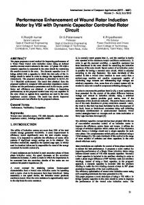
Effect of active flap on dynamic stall The effect of the active flap on dynamic stall was examined further so as to develop an improved physical understanding of the mechanism of power reduction. The results are presented in Fig. 19 which shows
23
the angle of attack variation over the rotor for the case of µ = 0.35 and CT /σ = 0.1. The results are presented for both power reduction as well as simultaneous vibration and power reduction. The grey circular areas enclosed by the dashed lines, shown in Fig. 19, represent the reversed flow region. It is evident from Fig. 19 that the active flap has a distinct and noticeable effect on the angle of attack distribution. However, the total area of the dynamic stall region on the retreating side is not significantly affected by the active flap either during power reduction or simultaneous vibration and power reduction. This implies that power enhancement is accomplished by reduced power losses on the advancing side, due to a complex redistribution of the unsteady aerodynamic loading, rather than stall alleviation. The apparently independent nature of the objectives of stall alleviation and power reduction have been also noted by several other studies dealing with the IBC approach (Refs. 4, 27, 39).
Conclusions
The results presented in this paper have indicated that the ACF system implemented either in a single or dual flap configurations is capable of simultaneously reducing vibration and enhancing rotor performance. The numerical simulations are carried out at µ = 0.35 and 0.4 where the dynamic stall is significant, on a rotor configuration that resembles an MBB BO-105. The principal conclusions of this study are summarized below:
1. The
ACF
system is effective for rotor performance enhancement, when the objective consists exclu-
sively of rotor power. Power reductions of nearly 4% and 6.37% are obtained at advance ratios of 0.35 and 0.40, respectively. Power reduction appears to result from an improved re-distribution of the unsteady aerodynamic loading on the rotor disk induced by the active flaps, which reduces power losses on the advancing side. 2. The rotor power reduction is usually accompanied by a significant increase in vibration levels, when
24
the controller is tuned only for power enhancement. 3. Simultaneous reduction of vibration and rotor power reduction is feasible, and the amount of performance enhancement and vibration reduction depends on the advance ratio and rotor loading. The range of power enhancement is between 1-4%, and this is accompanied by vibration reduction of 4770% . The
ACF
approach is more effective for rotor power reduction and simultaneous reduction of
power and vibration at higher rotor thrust levels at the advance ratio of µ = 0.35, or higher advance ratios at lower thrust levels. 4. A nonlinear optimizer LSQNONLIN available in the MATLAB package is also used with off-line identification to determine the optimal vibration and power reductions possible. Compared to the optimizer, the adaptive HHC algorithm produces good performance combined with superior numerical efficiency. The higher level of power reduction obtained using
LSQNONLIN
indicate the importance of nonlin-
earities in the performance enhancement problem.
Acknowledgments This research was supported by the FXB Center for Rotary and Fixed Wing Air Vehicle Design. Partial support of an ARO grant 02-1-0202 with Dr. B. Lamattina as grant monitor is acknowledged. Partial support for this project by RITA under WBS: 04-B-01-01.7-A.16 is also acknowledged. The authors want to thank Walter Sonneborn for suggesting that performance be emphasized in conjunction with vibration reduction.
References 1) Friedmann, P. P. , “Rotary Wing Aeroelasticity - Current Status and Future Trends,” AIAA Journal, Vol. 42, (10), October 2004, pp. 1953–1972. 2) Friedmann, P. P. and Millott, T. A. , “Vibration Reduction in Rotorcraft Using Active Control: A Comparison of Various Approaches,” Journal of Guidance, Control, and Dynamics, Vol. 18, (4), JulyAugust 1995, pp. 664–673. 3) Splettstoesser, W. , Kube, R. , Wagner, W. , Seelhorst, U. , Boutier, A. , Micheli, F. , Mercker, E. , and Pengel, K. , “Key Results From a Higher Harmonic Control Aeroacoustic Rotor Test (HART),” Journal of the American Helicopter Society, Vol. 42, (1), January 1997, pp. 58–78.
25
4) Jacklin, S. A. , “Second Test of a Helicopter Individual Blade Control System in the NASA Ames 40 by 80 Foot Wind Tunnel,” American Helicopter Society 2nd International Aeromechanics Specialists’ Conference, Bridgeport, CT, October 11-13, 1995. 5) Jacklin, S. A. , Haber, A. , de Simone, G. , Norman, T. , Kitaplioglu, C. , and Shinoda, P. , “Full-Scale Wind Tunnel Test of an Individual Blade Control System for a UH-60 Helicopter,” American Helicopter Society 58th Annual Forum Proceedings, Montreal, Canada, June 11-13, 2002. 6) Johnson, W. , “Self-Tuning Regulators for Multicyclic Control of Helicopter Vibrations,” NASA-TP1996, March 1982. 7) Patt, D. , Liu, L. , Chandrasekar, J. , Bernstein, D. S. , and Friedmann, P. P. , “Higher-HarmonicControl Algorithm for Helicopter Vibration Reduction Revisited,” Journal of Guidance, Control, and Dynamics, Vol. 28, (5), September-October 2005, pp. 918–930. 8) Millott, T. A. and Friedmann, P. P. , “Vibration Reduction in Helicopter Rotors Using an Actively Controlled Partial Span Trailing Edge Flap Located on the Blade,” NASA-CR-4611, June 1994. 9) Myrtle, T. F. and Friedmann, P. P. , “Application of a New Compressible Time Domain Aerodynamic Model to Vibration Reduction in Helicopters Using an Actively Controlled Flap,” Journal of the American Helicopter Society, Vol. 46, (1), January 2001, pp. 32–43. 10) de Terlizzi, M. and Friedmann, P. P. , “Active Control of BVI Induced Vibrations Using a Refined Aerodynamic Model and Experimental Correlation,” American Helicopter Society 55th Annual Forum Proceedings, Montreal, Canada, May 25-27, 1999. 11) Depailler, G. and Friedmann, P. P. , “Alleviation of Dynamic Stall Induced Vibrations Using Actively Controlled Flaps,” American Helicopter Society 58th Annual Forum Proceedings, Montreal, Canada, June 11-13, 2002. 12) Depailler, G. and Friedmann, P. P. , “Alleviation of Rotor Vibrations Induced By Dynamic Stall Using Actively Controlled Flaps With Freeplay,” 28th European Rotorcraft Forum, Bristol, UK, September 17-20, 2002. 13) Friedmann, P. P. , de Terlizzi, M. , and Myrtle, T. F. , “New Developments in Vibration Reduction with Actively Controlled Trailing Edge Flaps,” Mathematical and Computer Modelling, Vol. 33, 2001, pp. 1055–1083. 14) Straub, F. K. and Charles, B. D. , “Aeroelastic Analysis of Rotors with Trailing Edge Flaps Using Comprehensive Codes,” Journal of the American Helicopter Society, Vol. 46, (3), July 2001, pp. 192– 199. 15) Koratkar, N. A. and Chopra, I. , “Wind Tunnel Testing of a Smart Rotor Model with Trailing Edge Flaps,” Journal of the American Helicopter Society, Vol. 47, (4), October 2002, pp. 263–272. 16) Fulton, M. and Ormiston, R. A. , “Small-Scale Rotor Experiments with On-Blade Elevons to Reduce Blade Vibratory Loads in Forward Flight,” American Helicopter Society 54th Annual Forum Proceedings, Washington, DC, May 1998, pp. 433–451. 17) Straub, F. K. , Kennedy, D. K. , Bomzalski, D. B. , Hassan, A. A. , Ngo, H. , Anand, V. R. , and Birchette, T. S. , “Smart Material Actuated Rotor Technology - SMART,” Proceedings of the 41th Structures, Structural Dynamics and Materials Conference, Atlanta, GA, April 2000. AIAA Paper No. 2000-1715.
26
18) Straub, F. K. , Kennedy, D. K. , Stemple, A. D. , Anand, V. R. , and Birchette, T. S. , “Development and Whirl Tower Test of the SMART Active Flap Rotor,” Proceedings of SPIE: Smart Structures and Materials 2004, Vol. 5388, July 2004, pp. 202–212. 19) Kloeppel, V. and Enenkl, B. , “Rotor Blade Control by Active Helicopter Servo Flaps,” Proceedings of the International Forum on Aeroelasticity and Structural Dynamics, Munich, Germany, June 28 – July 01, 2005. 20) Patt, D. , Liu, L. , and Friedmann, P. P. , “Rotorcraft Vibration Reduction and Noise Prediction Using a Unified Aeroelastic Response Simulation,” Journal of the American Helicopter Society, Vol. 50, (1), January 2005. 21) Patt, D. , Liu, L. , and Friedmann, P. P. , “Simultaneous Vibration and Noise Reduction in Rotorcraft Using Aeroelastic Simulation,” Journal of the American Helicopter Society, Vol. 51, (2), April 2006. 22) Liu, L. , Friedmann, P. P. , and Patt, D. , “Simultaneous Vibration and Noise Reduction in Rotorcraft Practical Implementation Issues,” Proceedings of the 46th AIAA/ASME/ASCE/AHS/ACS Structures, Structural Dynamics and Materials Conference, Austin, TX, April 2005. 23) Roth, D. , “Advanced Vibration Reduction by IBC Technology,” 30th European Rotorcraft Forum, Marseille, France, September 14-16, 2004. 24) Ham, N. D. , “Helicopter Stall Alleviation Using Individual Blade Control,” Paper 50A, Tenth European Rotorcraft Forum, The Hague, The Netherlands, August 28-31 1984, pp. 1–4. 25) Ham, N. D. , “Helicopter Individual-Blade-Control Research at MIT: 1977-1985,” Vertica, Vol. 11, 1987, pp. 109–122. 26) Shaw, J. , Albion, N. , Hanker, E. J. , and Teal, R. S. , “Higher Harmonic Control: Wind Tunnel Demonstration of Fully Effective Vibratory Hub Force Suppression,” Journal of the American Helicopter Society, Vol. 34, (1), January 1989, pp. 14–25. 27) Swanson, S. M. , Jacklin, S. A. , Blaas, A. , Niesl, G. , and Kube, R. , “Reduction of Helicopter BVI Noise, Vibration, and Power Consumption through Individual Blade Control,” American Helicopter Society 51st Annual Forum Proceedings, Fort Worth, TX, May 9-11, 1995, pp. 662–680. 28) Nguyen, K. and Chopra, I. , “Effects of Higher Harmonic Control on Rotor Performance and Control Loads,” Journal of the American Helicopter Society, Vol. 29, (3), May–June 1992. 29) Cheng, R. P. , Theodore, C. R. , and Celi, R. , “Effects of Two/rev Higher Harmonic Control on Rotor Performance,” Journal of the American Helicopter Society, Vol. 48, (1), January 2003, pp. 18–27. 30) Cheng, R. P. and Celi, R. , “Optimum Two-Per-Revolution Inputs for Improved Rotor Performance,” Journal of Aircraft, Vol. 42, (6), November-December 2005, pp. 1409–1417. 31) Straub, F. K. , “Active Flap Control for Vibration Reduction and Performance Improvement,” American Helicopter Society 51st Annual Forum Proceedings, Fort Worth, TX, May 9-11, 1995, pp. 381–392. 32) Patt, D. , Liu, L. , and Friedmann, P. P. , “Active Flaps for Noise Reduction: A Computational Study,” American Helicopter Society 61st Annual Forum Proceedings, Grapevine, TX, June 1-3, 2005. 33) Schmitz, F. H. , Rotor Noise, Aeroacoustics of Flight Vehicles, ed. H. H. Hubbard, Vol.1. Acoustical Society of America and American Institute of Physics, New York, 1995. pp. 65-149.
27
34) Liu, L. , “BVI Induced Vibration and Noise Alleviation By Active and Passive Approaches,” Ph.D. Dissertation, University of Michigan, Ann Arbor, 2005. 35) Petot, D. , “Differential Equation Modeling of Dynamic Stall,” La Recherche A´erospatiale, Vol. 5, 1989, pp. 59–71. 36) Coleman, T. and Li, Y. , “On the Convergence of Reflective Newton Methods for Large-Scale Nonlinear Minimization Subject to Bounds,” Mathematical Programming, Vol. 67, (2), October 1994, pp. 189– 224. 37) Coleman, T. and Li, Y. , “An Interior, Trust Region Approach for Nonlinear Minimization Subject to Bounds,” SIAM Journal on Optimization, Vol. 6, 1996, pp. 418–445. 38) Wernicke, R. K. and Drees, J. M. , “Second Harmonic Control,” American Helicopter Society 19th Annual Forum Proceedings, Washington, D.C., 1963, pp. 1–7. 39) Nguyen, K. , “Active Control of Helicopter Blade Stall,” Journal of the American Helicopter Society, Vol. 35, (1), January–February 1998, pp. 91–98.
28
Table 1: Hingeless blade configuration resembling MBB BO-105 used in the simulations. Rotor Data R = 4.91 m Mb = 52 kg Nb = 4 c = 0.05498R ωF = 1.12, 3.41, 7.62 Cdo = 0.01 ωL = 0.73, 4.46 Cmo = 0.0 ωT = 3.17 ao = 2π θtw = −8◦ , from root to tip β p = 2.5◦ γ = 5.5 σ = 0.07 Nominal Operating Condition CT /σ = 0.0714 µ = 0.35, 0.40 Ω = 425 RPM
29
Table 2: Flap configuration. cc = 0.25c mc = 0.0625 Single Servo Flap xc = 0.75R Lc = 0.12R Dual Servo Flap Lc1 = 0.06R xc1 = 0.72R 2 Lc2 = 0.06R xc = 0.92R
30
Table 3: Summary of rotor power reduction during Power Reduction (PR) and Simultaneous Reduction(SR), CT /σ = 0.0714, µ = 0.35. Objective Power Reduction(PR) Controller HHC LSQNONLIN Flap Config. Single Dual Single Baseline Power 0.00670286 0.00681677 0.00670286 0.00658692 0.00669656 0.00654460 Controlled Reduction(%) 1.73 1.76 2.36
31
Simultaneous Reduction(SR) HHC
Single 0.00670286 0.00667611 0.40
Dual 0.00681677 0.00677104 0.67
LSQNONLIN
Single 0.00670286 0.00665546 0.71
Table 4: Rotor power reduction with single flap located at various spanwise locations, CT /σ = 0.0714, µ = 0.35. Flap Center (xc ) 0.75R Baseline Power 0.00670286 Controlled 0.00658692 Reduction(%) 1.73
32
0.85R 0.00663195 0.00654061 1.38
0.94R 0.00571054 0.00548369 2.04
Table 5: Rotor power reduction with single flap at higher rotor thrust levels, µ = 0.35. CT /σ Controller Baseline Power Controlled Reduction(%) † ‡
0.0714
0.0857
PR†
SR‡
0.00670286 0.00658692 1.73
0.00670286 0.00667611 0.40
PR 0.00859831 0.00835513 2.83
Power Reduction. Simultaneous Power and Vibration Reduction.
33
SR 0.00859831 0.00847245 1.46
0.1 PR 0.01088269 0.01045713 3.91
SR 0.01088269 0.01068480 1.82
Table 6: Rotor power reduction with single flap at higher advance ratios. µ CT /σ Controller Baseline Power Controlled Reduction(%)
0.35 0.0714 PR 0.00670286 0.00658692 1.73
0.40 0.0643
SR 0.00670286 0.00667611 0.40
34
PR 0.01026845 0.00961412 6.37
SR 0.01026845 0.00985403 4.04
Figure 1: An Overview of Active Control Techniques.
35
Flap Deflection(deg)
5 4 3 2 1 0 −1 −2 −3 −4 −5 0
180
5 4 3 2 1 0 −1 −2 −3 −4 −5 360 0
Azimuth(deg)
Inboard flap Outboard flap
180
360
Azimuth(deg)
(a) Single flap configuration
(b) Dual flap configuration
Figure 2: Flap deflection during power reduction with single and dual flap configurations, CT /σ = 0.0714, µ = 0.35.
36
Nondimensional 4/rev Vibratory Hub Loads
0.0030
Baseline PR, 1 Flap PR, 2 Flaps
0.0025 0.0020 0.0015 0.0010 0.0005 0.0000 FHX4
FHY4
FHZ4
MHX4
MHY4
MHZ4
Figure 3: Vibration levels during power reduction with single and dual flap configurations, CT /σ = 0.0714, µ = 0.35.
37
Flap Deflection(deg)
5 4 3 2 1 0 −1 −2 −3 −4 −5 0
180
5 4 3 2 1 0 −1 −2 −3 −4 −5 360 0
Azimuth(deg)
Inboard flap Outboard flap
180
360
Azimuth(deg)
(a) Single flap configuration
(b) Dual flap configuration
Figure 4: Flap deflection during simultaneous reduction with single and dual flap configurations, CT /σ = 0.0714, µ = 0.35.
38
Nondimensional 4/rev Vibratory Hub Loads
0.0020
Baseline SR, 1 Flap SR, 2 Flaps
0.0015 0.0010 0.0005 0.0000 FHX4
FHY4
FHZ4
MHX4
MXY4
MHX4
Figure 5: Vibration levels during simultaneous vibration and power reduction with single and dual flap configurations, CT /σ = 0.0714, µ = 0.35.
39
Flap Deflection(deg)
5 4 3 2 1 0 −1 −2 −3 −4 −5 0
180
360
Azimuth(deg)
Figure 6: Flap deflection during power reduction using LSQNONLIN with single flap configuration, CT /σ = 0.0714, µ = 0.35.
40
Nondimensional 4/rev Vibratory Hub Loads
0.0030
Baseline PR, 1 Flap, LSQNONLIN
0.0025 0.0020 0.0015 0.0010 0.0005 0.0000 FHX4
FHY4
FHZ4
MHX4
MHY4
MHZ4
Figure 7: Vibration levels during power reduction using LSQNONLIN with single flap configuration, CT /σ = 0.0714, µ = 0.35.
41
Flap Deflection(deg)
5 4 3 2 1 0 −1 −2 −3 −4 −5 0
180
360
Azimuth(deg)
Figure 8: Flap deflection during simultaneous reduction using LSQNONLIN with single flap configuration, CT /σ = 0.0714, µ = 0.35.
42
Nondimensional 4/rev Vibratory Hub Loads
0.0020
Baseline SR, 1 Flap, LSQNONLIN
0.0015 0.0010 0.0005 0.0000 FHX4
FHY4
FHZ4
MHX4
MXY4
MHX4
Figure 9: Vibration levels during simultaneous power and vibration reduction using LSQNONLIN with single flap configuration, CT /σ = 0.0714, µ = 0.35.
43
Figure 10: Comparison of optimization history using HHC and LSQNONLIN, showing Jpower vs. Jvib , CT /σ = 0.0714, µ = 0.35.
44
Nondimensional 4/rev Vibratory Hub Loads
0.0020
Baseline PR, Conv. IBC SR, Conv. IBC
0.0015 0.0010 0.0005 0.0000 FHX4
FHY4
FHZ4
MHX4
MXY4
MHX4
Figure 11: Vibration levels during power reduction and simultaneous reduction using conventional IBC, CT /σ = 0.0714, µ = 0.35.
45
IBC root pitch angle (deg)
5 4 3 2 1 0 −1 −2 −3 −4 −5 0
PR SR
180
360
Azimuth(deg)
Figure 12: Root pitch angle during power reduction and simultaneous reduction using conventional IBC, CT /σ = 0.0714, µ = 0.35.
46
Nondimensional 4/rev Vibratory Hub Loads
0.0050
Baseline Power Reduction Simul. Reduction
0.0040 0.0030 0.0020 0.0010 0.0000 FHX4
FHY4
FHZ4
MHX4
MHY4
MHZ4
Figure 13: Vibration levels during power reduction and simultaneous reduction with single flap configuration, CT /σ = 0.0857, µ = 0.35.
47
Nondimensional 4/rev Vibratory Hub Loads
0.0080
Baseline Power Reduction Simul. Reduction
0.0070 0.0060 0.0050 0.0040 0.0030 0.0020 0.0010 0.0000 FHX4
FHY4
FHZ4
MHX4
MHY4
MHZ4
Figure 14: Vibration levels during power reduction and simultaneous reduction with single flap configuration, CT /σ = 0.1, µ = 0.35.
48
Flap Deflection(deg)
5 4 3 2 1 0 −1 −2 −3 −4 −5 0
PR SR
180
360
Azimuth(deg)
Figure 15: Flap deflection during power reduction and simultaneous reduction with single flap configuration, CT /σ = 0.0857, µ = 0.35.
49
Flap Deflection(deg)
5 4 3 2 1 0 −1 −2 −3 −4 −5 0
PR SR
180
360
Azimuth(deg)
Figure 16: Flap deflection during power reduction and simultaneous reduction with single flap configuration, CT /σ = 0.1, µ = 0.35.
50
Nondimensional 4/rev Vibratory Hub Loads
0.0080
Baseline Power Reduction Simul. Reduction
0.0070 0.0060 0.0050 0.0040 0.0030 0.0020 0.0010 0.0000 FHX4
FHY4
FHZ4
MHX4
MHY4
MHZ4
Figure 17: Vibration levels during power reduction and simultaneous reduction with single flap configuration, CT /σ = 0.0643, µ = 0.40.
51
Flap Deflection(deg)
5 4 3 2 1 0 −1 −2 −3 −4 −5 0
PR SR
180
360
Azimuth(deg)
Figure 18: Flap deflection during power reduction and simultaneous reduction with single flap configuration, CT /σ = 0.0643, µ = 0.40.
52
Relative Wind 5
8
5 4
6 7
8 7
11
(b) Power Reduction
14
12
9
8
18
15 13
19
11 10
8
19 16
9
20
12 10
22
6
6
22
20
21
8 6
5
9
23
3
12
1
5
20
18
15
4
7
21
23
25 24
19
1
-1
4
3
24 23
0
2
5
21 20 19
11
3
9
25
22
(a) Baseline
5
20
23
5
10
19 17
13
16
10 11
4
0
7 8
24
20
22
21
1 14 6
0 1
21
22
23
4
21 20
6
1
2 3
3
15
25
19
23
2
4
11
18
22
7 8
10
7
21
13
17 18
4
9
-1
16 18
13
20
15
12
1
9
19
6 7
2
12
19
5
14 13
3 4
10
11
14
16 17
(c) Simul Reduction
Figure 19: Blade angle of attack contour plots for the baseline and during active control using the ACF, CT /σ = 0.1, µ = 0.35.
53
List of Tables 1
Hingeless blade configuration resembling MBB BO-105 used in the simulations. . . . . . . 29
2
Flap configuration. . . . . . . . . . . . . . . . . . . . . . . . . . . . . . . . . . . . . . . . 30
3
Summary of rotor power reduction during Power Reduction (PR) and Simultaneous Reduction(SR), CT /σ = 0.0714, µ = 0.35. . . . . . . . . . . . . . . . . . . . . . . . . . . . . . . 31
4
Rotor power reduction with single flap located at various spanwise locations, CT /σ = 0.0714, µ = 0.35. . . . . . . . . . . . . . . . . . . . . . . . . . . . . . . . . . . . . . . . 32
5
Rotor power reduction with single flap at higher rotor thrust levels, µ = 0.35. . . . . . . . . 33
6
Rotor power reduction with single flap at higher advance ratios.
. . . . . . . . . . . . . . . 34
List of Figures 1
An Overview of Active Control Techniques.
2
Flap deflection during power reduction with single and dual flap configurations, CT /σ = 0.0714, µ = 0.35. . . . . . . . . . . . . . . . . . . . . . . . . . . . . . . . . . . . . . . . 36
3
Vibration levels during power reduction with single and dual flap configurations, CT /σ = 0.0714, µ = 0.35. . . . . . . . . . . . . . . . . . . . . . . . . . . . . . . . . . . . . . . . 37
4
Flap deflection during simultaneous reduction with single and dual flap configurations, CT /σ = 0.0714, µ = 0.35. . . . . . . . . . . . . . . . . . . . . . . . . . . . . . . . . . . . 38
5
Vibration levels during simultaneous vibration and power reduction with single and dual flap configurations, CT /σ = 0.0714, µ = 0.35. . . . . . . . . . . . . . . . . . . . . . . . . 39
6
Flap deflection during power reduction using LSQNONLIN with single flap configuration, CT /σ = 0.0714, µ = 0.35. . . . . . . . . . . . . . . . . . . . . . . . . . . . . . . . . . . . 40
7
Vibration levels during power reduction using LSQNONLIN with single flap configuration, CT /σ = 0.0714, µ = 0.35. . . . . . . . . . . . . . . . . . . . . . . . . . . . . . . . . . . . 41
8
Flap deflection during simultaneous reduction using LSQNONLIN with single flap configuration, CT /σ = 0.0714, µ = 0.35. . . . . . . . . . . . . . . . . . . . . . . . . . . . . . . 42
9
Vibration levels during simultaneous power and vibration reduction using LSQNONLIN with single flap configuration, CT /σ = 0.0714, µ = 0.35. . . . . . . . . . . . . . . . . . . 43
10
Comparison of optimization history using HHC and LSQNONLIN, showing Jpower vs. Jvib , CT /σ = 0.0714, µ = 0.35. . . . . . . . . . . . . . . . . . . . . . . . . . . . . . . . . . . . 44
11
Vibration levels during power reduction and simultaneous reduction using conventional IBC, CT /σ = 0.0714, µ = 0.35. . . . . . . . . . . . . . . . . . . . . . . . . . . . . . . . . . . . 45
12
Root pitch angle during power reduction and simultaneous reduction using conventional IBC, CT /σ = 0.0714, µ = 0.35. . . . . . . . . . . . . . . . . . . . . . . . . . . . . . . . . 46
13
Vibration levels during power reduction and simultaneous reduction with single flap configuration, CT /σ = 0.0857, µ = 0.35. . . . . . . . . . . . . . . . . . . . . . . . . . . . . . . 47
14
Vibration levels during power reduction and simultaneous reduction with single flap configuration, CT /σ = 0.1, µ = 0.35. . . . . . . . . . . . . . . . . . . . . . . . . . . . . . . . . 48
54
. . . . . . . . . . . . . . . . . . . . . . . . . 35
15
Flap deflection during power reduction and simultaneous reduction with single flap configuration, CT /σ = 0.0857, µ = 0.35. . . . . . . . . . . . . . . . . . . . . . . . . . . . . . . 49
16
Flap deflection during power reduction and simultaneous reduction with single flap configuration, CT /σ = 0.1, µ = 0.35. . . . . . . . . . . . . . . . . . . . . . . . . . . . . . . . . 50
17
Vibration levels during power reduction and simultaneous reduction with single flap configuration, CT /σ = 0.0643, µ = 0.40. . . . . . . . . . . . . . . . . . . . . . . . . . . . . . . 51
18
Flap deflection during power reduction and simultaneous reduction with single flap configuration, CT /σ = 0.0643, µ = 0.40. . . . . . . . . . . . . . . . . . . . . . . . . . . . . . . 52
19
Blade angle of attack contour plots for the baseline and during active control using the ACF, CT /σ = 0.1, µ = 0.35. . . . . . . . . . . . . . . . . . . . . . . . . . . . . . . . . . . . . . 53
55