NEW DYNAMIC ROUTING AND ADAPTIVE SCHEDULING SCHEMES FOR BLUETOOTH RING SCATTERNETS T. Hassan, A. Kayssi, and A. Chehab Department of Electrical and Computer Engineering American University of Beirut Beirut 1107 2020, Lebanon
[email protected]
ABSTRACT This paper presents a new ring topology for Bluetooth scatternets, ring of masters (ROM), and shows how this structure and its formation considerations contribute to the simplicity of routing and robustness of the scatternet. The scheduling scheme, ROM adaptive scheduling (RAS), dynamically allocates time slots at the intra- and inter-piconet levels through a set of indicators that monitor node activity and packet accumulation at master node buffers. Simulations show that high throughput values are achieved with moderate packet delays and good percentages of delivery. Keywords: Bluetooth, piconet, scatternet formation, ring topology, routing.
1. INTRODUCTION About six years ago, a group of five leading manufacturers in the computing and telecom industry established a special interest group (SIG) to promote and market a new technology that is envisioned to become the de facto standard of short-range wireless connectivity. This technology was named Bluetooth in hope that it will significantly contribute to "uniting" neighboring devices the same way Harald Bluetooth, a 10th century king, succeeded in uniting the warring Viking tribes [1]. The Bluetooth (BT) radios operate in the unlicensed ISM band at 2.4 GHz, which is globally available, and use frequency hopping spread spectrum communications to combat interference. The Bluetooth specification [2] has defined two types of ad hoc networks: a small network with limited range and population, called piconet, and a second type, called scatternet, that interconnects the different neighboring piconets to form a larger and more capable network. A piconet is a star-shaped network that is composed of one coordinating node, called master, which deploys a central polling scheme to regulate the traffic and eliminate collisions among the transmissions of the remaining nodes, called slaves. The master and slave transmissions alternate in 625µs time slots resulting in a time-division duplex (TDD) system. To guarantee quality of service (QoS) within a piconet, the maximum number of participating nodes was limited to eight. A scatternet, on the other hand, is intended to interconnect several piconets by gateway nodes, called PMPs (Participants in Multiple Piconets), that sequentially participate in these piconets in a time-division basis. The key parameters a node uses to synchronize itself to the frequency hopping (FH) sequence of a certain piconet are the identity (unique device address) and clock offset of the master that are acquired during piconet formation. As a result, a bridge (or PMP) node maintains a set of identities and offsets for the masters of the piconets to which it belongs in order to select the proper pair during switching from one piconet to another [3]. While the operation details of a piconet are standardized to a large extent with BT-enabled products (realizing certain usage scenarios) that already available in the market, the scatternet concept is still a research issue with many free parameters left to the designers’ choice. The scatternet design problem started to receive a growing attention since around 2001. The rest of the paper is organized as follows. The next section presents previous work related to routing and scheduling in Bluetooth networks. Section 3 defines the ring-of-masters (ROM)
structure and compares it to previous ones. The adopted formation protocol, with some suggested improvements, appears in Section 4. Then, the routing protocol and scheduling schemes are presented in Section 5 and Section 6, respectively. Section 7 displays and discusses simulation results. Conclusions are provided in Section 8.
2. PREVIOUS WORK Several paradigms were used to address the problem of scatternet-wide routing. Table-driven routing was used in tree structures [4]. The drawback of such tables is the large size and critical data stored in the root node that may fail at any time leaving the scatternet elements in a chaos. Other authors suggest that the unique path between any pair of nodes in the tree topology facilitates the use of higher-layer destination identifiers, such as IP addressing, that any node can obtain by an address resolution protocol (ARP) query [5]. Although better than table-driven routing, this solution requires ARP caches for all nodes, which will grow in parallel to network size. The Bluetooth Network Encapsulation Protocol (BNEP), developed by the Bluetooth PAN working group, is intended to provide an Ethernet-like interface to IP [6]. BNEP utilizes the unique BT device addresses to build broadcast segments that are independent of rearrangements of network memberships. In its first release, BNEP works with piconets only, but has the potential to extend its functionality towards scatternets. An enhanced Ad-hoc On-demand Distance-Vector (AODV) protocol was proposed in [7] but the flooding of AODV to discover routes is not preferred in ad hoc environments. An approach similar to Dynamic Source Routing (DSR) was proposed in [8]. The problem of DSR protocols is the unbounded header size needed to store route information in packets. This introduces huge header overhead into the small Bluetooth packets in addition to the use of flooding in a similar way to AODV. The ring topology of BlueRings [9, 10] and ROM [11] significantly contributes to the simplicity of routing. No routing tables are needed provided that source and destination addresses are included in the packets to prevent looping. The ROM routing protocol presented in this paper uses only one algorithm to be run by master nodes compared to two algorithms needed in the ring structure in [10]. Most proposed scheduling algorithms deal with the issue of fair slot allocations at the piconet level [12, 13, 14]. No matter how fair these schemes are, packet forwarding and bridging overhead cannot be ignored in scatternets. There is a general consensus that traditional and simple polling schemes such as pure round robin (PRR), deficit round robin (DRR), and exhaustive round robin (ERR) are not suitable for the dynamic environments of Bluetooth ad hoc networks. Therefore, a group of algorithms were developed to address this critical issue in tree structures [15] and general structures [7, 16]. In this work, we develop a dynamic scatternet-wide scheduling algorithm for ROM; simulation results reveal the efficiency of the algorithm.
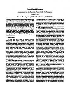
3. THE PROPOSED RING STRUCTURE We will call the topology presented in this paper Ring of Masters (ROM) since it is composed mainly of master nodes that are responsible for forwarding inter-piconet traffic in addition to their original task of serving their piconets. These masters are even in number (for scheduling purposes) and constitute network bridges of the master/slave (MS) type. Since Bluetooth bridges can exist in only one piconet at a time, master nodes periodically join the neighboring piconets in the anti-clockwise direction as “occasional” slaves. To guarantee quality of intra-piconet service, we limited the number of “pure” slaves (i.e. not members in other piconets) to four, resulting in up to five slaves per master in total. We select the main direction of routing to be clockwise although the structure itself is not directional (see Figure 1.)
Master Bridge Pure Slave
Figure 1: Ring of Masters (ROM) scatternet The decentralized ring structure is obviously better than tree [4] and star [17] topologies where the root or central node may become a traffic bottleneck overwhelmed by the increasing forwarding demands or even a weak point through which the whole structure may collapse. In [11] we showed how ROM exhibits smaller piconet count (versus number of nodes) and shorter network diameter than the previous two ring structures [9, 10], both called BlueRings. Moreover, a scatternet with limited piconet population experiences less interference. In addition, shorter routes result in shorter delays and lower power consumption. We consider our ROM topology most suitable for small computer labs or medium-sized loop sensor networks where most transmissions occur at the piconet or personal-area-network (PAN) level. Our focus in this paper, however, goes towards exploiting this structure to provide better scheduling and routing performance.
4. THE ROM FORMATION PROTOCOL To construct a ROM, we adopt the Bluetooth Topology Construction Protocol (BTCP) [18] as a centralized formation algorithm that can be used to virtually construct any topology. Being centralized, BTCP provides more flexibility in assigning roles to the various participating nodes than other formation protocols like LMS [19] and LSF [20]. Moreover, BTCP is fast and can bring 30 nodes into one scatternet in about 5.5 s. However, it assumes all nodes to be within radio range of each other. To obtain a more robust structure, we suggest that after ROM formation, each master broadcasts within its piconet the identities and clocks of its slaves and neighboring masters. This last step guarantees some kind of “mutual knowledge” among piconet members and contributes to the fault-tolerance capability as follows: By maintaining a small table within all piconet members with entries ordered according to device characteristics (collected during scatternet formation) and which of them is the next “qualified master”, a piconet could tolerate the failure of its master and re-organize itself again starting from the second and shorter establishment step, the paging phase. In other words, after nodes recognize that their master is no more available, the next qualified master enters the page state, while the rest of nodes go into the page scan state. Avoiding the total piconet collapse contributes to the robustness at the scatternet level and ensures than any new master will quickly contact its neighbors to close the ring. This way a ROM structure can tolerate the loss of half its masters at the same time provided that no two of them are neighbors.
5. THE ROM ROUTING PROTOCOL The implemented routing protocol is simple in the sense that neither does it require routing tables nor does it store routing information in packet headers. Moreover, it prevents looping and adapts to dynamic environments. Only masters participate in routing by checking the source and
destination addresses (48-bit unique numbers) of each packet to determine whether it should be routed to their piconets, discarded, or forwarded as inter-piconet flow (see Figure 2).
start
yes
DA = my BD_ADD R?
n o Accept the packet and forward to upper layer
n o
DA in my piconet?
n o
DA = old piconet member?
yes
yes Forward to local slave
SA=current piconet member?
n o
yes
Discard and send N/A to source node
Discard and send N/A to source node
SA= old piconet member?
n o
yes Orphan packet! Discard it
Forward packet to next master bridge
End
Figure 2: The ROM routing To accommodate the changing piconet membership efficiently, the address of any leaving node is kept for a while in its piconet in order to: • Reply on behalf of lost destination nodes indicating that they are no longer available. • Discover and discard orphan packets if their sources have left and their destinations became no longer “remembered” in their piconets. It is worth noting here that the storage time of addresses of leaving nodes is not constant. It should be dynamically determined according to mobility conditions and join-and-leave activities. Finding an expression for this important factor is currently under consideration. By adding the stored addresses for routing efficiency to those we mentioned for fault tolerance, we obtain a table similar to Table 1 below. Table 1: Suggested table for piconet robustness and routing efficiency BD_ADDR 48-bit value 48-bit value 48-bit value 48-bit value 48-bit value 48-bit value
Clock 28-bit value 28-bit value 28-bit value 28-bit value N/A N/A
Description Peer slave
Priority 1
Peer slave
2
Bridge (right) Bridge (left) Old member Old member
N/A N/A N/A N/A
6. THE INTRA- AND INTER-PICONET SCHEDULING MECHANISMS Since masters are responsible for forwarding both intra- and inter-piconet packets, a complex scheduler is needed to make a balance between both types of transmissions to guarantee best bandwidth utilization and minimum packet delay or discard. We developed the ROM adaptive scheduling (RAS) algorithm to handle these issues. The RAS protocol in each master starts by assigning equal number of slots (400 slots) for intra- and inter-piconet intervals. The combination of these two intervals creates what is called "ROM cycle" that lasts for half a second (800 slots) as shown in Figure 3.
Intra-piconet (400 slots)
Inter-piconet (400 slots)
( (800 slots) ROM cycle
Figure 3: ROM scheduling cycle The relation between a master and any of its slaves (pure or bridge) in each meeting my last for a hundred time slots that are divided into five intervals called testing periods, as shown in Figure 4. This arrangement helps in allocating the necessary number of slots according to network conditions in a dynamic weighted round robin fashion. Testing Period 0
20
40
60
80
100
Figure 4: The five testing periods during a complete master-slave session. We can summarize the main criteria used in RAS in the following points: • Master queue status: indicates how many packets are to be delivered to the current slave. • Receiving queue status: monitors the receiving buffer for overflow conditions during a master-slave session. • History bit: records the identities of inactive slaves in the last round. • Intra-piconet activity indicator: calculates the current ratio between the “full” slots and the total number of slots spent within a piconet. • Inter-piconet traffic indicator: monitors the accumulation of inter-piconet traffic within a master regardless of its origins. Based on all or some of the above criteria, a master may switch from a slave to another, use multislot packets, or move the boundary between the intra- and inter-piconet intervals in either direction using a special mechanism called local extra time (LET) protocol. To consume the full hundred time slots, the master and the slave, or the master alone, should have data to send. If only the slave were sending, four testing periods (equivalent to 80 slots) would be used in order to minimize the wasted slots coming from the master side as a result of the timedivision duplex (TDD) scheme. More specifically, the master switches to a new slave if one of the following conditions was met at the end of any testing period: • If both parties have no data to send. • If only the slave were sending and the receiving buffer of the master (500 packets/destination) has become full.
• If the inter-piconet traffic indicator reached or exceeded the 150-packet threshold and the current slave was a source of such traffic while the master has no data to deliver (since a master can deliver a maximum of 160 inter-piconet packets in one ROM cycle). • If the history bit related to any slave was equal to 1, this slave is not polled for one ROM cycle. To support efficient use of radio time, the Bluetooth specs have defined two multi-slot ACL packets in the form of 3- and 5-slot packets. These packets can carry multiples of payloads more than their single-slot counterpart thus achieving higher throughput and lower delays. Moreover, simulations [21] have shown that multi-slot packets yield lower interference levels due to the relatively slower frequency transitions they incur. We chose to utilize multi-slot packets if any of the following cases were true at the end of any testing period: • If the master were the only sending party. • If both parties have data to send but the master buffer which carries packets to be delivered to the current slave is filled up to 75% of its capacity or more. This 75% threshold is intended to prevent buffer overflow and packet discarding. • If both parties have data to send but the receiving buffer of the master has become full. • If both parties have data to send but the inter-piconet traffic indicator reached the 150-packet threshold or more and the current slave was a source of such traffic. The third feature of ROM scheduling is its ability to move the boundary between the intra- and inter-piconet intervals to either side to accommodate traffic changes and urgent needs. Recall that a ROM cycle consists of 400 intra-piconet timeslots that are allocated dynamically in a round robin fashion. The 400 inter-piconet timeslots are distributed to the two neighboring bridge nodes by alternatively visiting each of them twice per cycle. We consider serving piconet members as the ultimate goal of the master because only the devices that are willing to interact with each other most of the time should group into the same piconet. That said, the switching during the intra-piconet interval is always kept within the pure slaves to guarantee the expected high level of service. During inter-piconet intervals, on the other hand, the failure to sustain the link between the master and the bridge node during any of the four visits means that both of them (recall that a bridge node is also a master) will tear down the connection and return to their respective piconets to serve until the time of the next visit comes. In fact, we preferred to use the Honoring-Periodic Dynamic-Window (HPDW) rendezvous point scheme [6] for the inter-piconet links in order to achieve better traffic delay guarantee. The cost of this strict inter-piconet scheduling is that 20% of the allocated 400 timeslots may be lost in checking the bridge nodes in case there is no traffic to forward. To balance the time taken from the inter-piconet links during light loads, we introduce the local extra time (LET) protocol. The inter-piconet traffic indicator initiates measures (such as change slave or multi-slot activation) to keep the buffered inter-piconet packets around a certain level (150 packets) that could be delivered during one cycle. Storing excessive amounts of packets to be forwarded makes no sense and poses more delays on these packets. Occasionally, the master accumulates a large number of packets to be forwarded, especially from the anti-clockwise bridge. If the inter-piconet traffic indicator reaches the 300-packet threshold, which is an alarming level, the master sends a LET REQUEST (LETREQ) for the clockwise bridge node. Accepting the LETREQ means that both masters will extract hundred timeslots from their intra-piconet intervals and add it to their two 100-slot visits available by default. Hence, the master which receives the request only accepts it after checking the intra-piconet activity indicator and finding its value equal to 50% or less. If the LET protocol is activated, it remains in effect until the inter-piconet indicator drops to 150 buffered packets or less; then both parties regain their ordinary schedule.
7. PERFORMANCE TESTING AND SIMULATION RESULTS We built the network model using SimJava [22], a discrete-event object-oriented simulation package. The simulated ROM network is stationary and consists of four full piconets, i.e. 20 nodes. Single- and multi-slot ACL packets were used with a simulation time of 96,000 time slots (equivalent to 60 seconds). All the simulations consist of randomly selected source-destination pairs where no two sources can send to the same destination. This last restriction was imposed in order to have a nearly constant two-way data rate with respect to each node, thus having similar pattern to that in [10] with which the comparison is made. Each pair represents a connection between two devices in the network that lasts till the end of the simulation time. Every source transmits 366-bit packets at a constant bit rate (CBR) of 800 packets per second except when multi-slot delivery is used by master nodes. It is worth noting here that multi-slot packets are treated at the packet level with respect to single-slot packets since dealing with data at the bit level complicates the simulation and makes measuring delays infeasible. • We investigated the performance of ROM in two major dimensions: the number of simultaneous connections and the workload emphasis. The number of connections varies from 4 to 16 while the traffic conditions range from intra- to inter-piconet concentration (Figure 5 and Figure 6, respectively). Throughput - More intra-piconet traffic 900
Throughput (Kbps)
800 700 600 500 400 300 200 100 0
a
4
6
8
10
12
14
16
Num ber of Sim ultaneous Connections
Packet Delay - More intra-piconet traffic 0.45
Packet Delay (sec)
0.4 0.35 0.3 0.25 0.2 0.15 0.1 0.05 0 4
b
6
8
10
12
14
16
Number of Simultaneous Connections
Delivery Rate - More intra-piconet traffic 105
Percentage
100 95 90 85 80
c
4
6
8
10
12
14
16
Num ber of Sim ultaneous Connections
Figure 5: Throughput (a), packet delay (b), and delivery rate (c) for more intra-piconet traffic.
Throughput (Kbps)
Throughput - More inter-piconet traffic 500 450 400 350 300 250 200 150 100 50 0 4
a
6
8
10
12
14
16
Number of Simultaneous Connections
Packet Delay - More inter-piconet traffic
Packet Delay (sec)
0.8 0.7 0.6 0.5 0.4 0.3 0.2 0.1 0 4
b
6
8
10
12
14
16
Number of Simultaneous Connections
Delivery Rate - More inter-piconet traffic
Percentage
100 90 80 70 60 50
c
4
6
8
10
12
14
16
Number of Simultaneous Connections
Figure 6: Throughput (a), packet delay (b), and delivery rate (c) for more inter-piconet traffic. The main three metrics used to evaluate our work are: • The network throughput. • The average end-to-end latency. • The delivery rate. We compared our results to those of BlueRing [10], which use the same testing parameters, although the authors did not mention anything about their deployed scheduling scheme. For each number of simultaneous connections, a set of 20 simulations was performed; the average was calculated, and the ranges shown were determined by adding and subtracting the value of standard deviation from this average. For simplicity, we assume that collisions due to frequency overlapping do not happen. Moreover, each filled time slot is equivalent to 366 bits including the access code, header, payload header, payload, and CRC.
Under the first condition, a ratio of 3:1 of the traffic is within piconets (intra-piconet). We expect to have substantial increase in throughput together with very low delays. The results are shown in Figure 5. Here, ROM outperforms BlueRing in throughput for more than 12 connections and in delay for less than 10 connections. This indicates that ROM succeeded using its LET protocol to increase the throughput at the expense of longer delays. When the inter- to intra-piconet traffic constitutes 3/4 of the packet flow, packets have to travel longer distances and thus experience longer delays. In this case, we obtain a clearer image of the ROM forwarding capabilities (see Figure 6). While throughput in BlueRing saturates at about 320 Kbps, the ROM values start at 375 Kbps for 6 connections until it reaches 450 Kbps for 16 connections. This higher throughput was achieved for about 0.1 s increase in delay with respect to BlueRing. We notice that the network throughput starts with small values since the ROM scheduling and routing capabilities are not used to their full extent. Then, the throughput increases until it reaches a saturation value. The average packet delay, on the other hand, increases a little bit as more simultaneous connections are added. This behavior is expected since an escalating number of sources and destinations will share the network resources which results in more time spent in the buffers for the packets before they reach their final destinations. However, variations in packet delays are very small in both cases which point to the ability of ROM to accommodate new loads efficiently. This conclusion goes in harmony with the recorded delivery rates that range from 100 down to 80 percent on average.
CONCLUSION This paper presented a new ring topology, ring of masters (ROM), and clarified how this structure and formation considerations contribute to the simplicity of routing and robustness of the scatternet. The developed scheduling scheme, ROM adaptive scheduling (RAS), dynamically allocates time slots at the intra- and inter-piconet levels through a set of indicators that monitor node activity and packet accumulation at master node buffers. Simulations show that high throughput values could be achieved with moderate packet delays and good percentages of delivery. Future work will include simulating the BTCP with many improved features that we suggest. Maintenance procedures may also be tested to prove their reliability and efficiency.
REFERENCES [1] B. Miller and C. Bisdikian, Bluetooth Revealed, Prentice Hall, 2nd edition, 2002. [2] Bluetooth SIG, Bluetooth Core Specifications v1.2, available at: http://www.bluetooth.com. [3] J. Haartsen, “Bluetooth- the Universal Radio Interface for Ad Hoc Wireless Connectivity,” [4] [5] [6] [7]
[8] [9]
Ericsson Review, no. 3, 1998. Available at: http://www.ericsson.se/review. G. Zaruba, S. Basagni, I. Chlamtac, “Bluetrees- Scatternet Formation to Enable BluetoothBased Ad Hoc Networks,” IEEE ICC 2001. G. Tan, A. Miu, J. Gottag, H. Balakrishnan, "Forming Scatternets from Bluetooth Personal Area Networks," MIT Technical Report, 2001. P. Johansson, M. Kazantzidis, R. Kapoor, M. Gerla, "Bluetooth: An Enabler for Personal Area Networking," IEEE Network, Sept/Oct 2001. L. Shek, Y. Kwok, "An Integrated Approach to Scatternet Traffic Management in Bluetooth Ad Hoc Networks", IEEE International Computer Software and Applications Conference, 2003. P. Bhagwat and A. Segall, "A Routing Vector Method (RVM) for Routing in Bluetooth Scatternets", IEEE MoMuC '99. F. Chun-Choong, C. Kee-Chaing, “BlueRings- Bluetooth Scatternets with Ring Structures”, IASTED Canada, WOC 2002.
[10] T. Lin, Y. Tseng, K. Chang, C. Tu, “Formation, Routing, and Maintenance Protocols for the
BlueRing Scatternet of Bluetooths,” HICSS-36, 2003. [11] T. Hassan, A. Kayssi, "Ring of Masters (ROM): A New Ring Structure for Bluetooth Scatternets," IEEE International Midwest Symposium on Circuits and Systems, Dec.2003. [12] M. Kalia, D. Bansal, and R. Shorey, "MAC Scheduling and SAR Policies for Bluetooth: A Master-Driven TDD Pico-Cellular Wireless System", 1999. IEEE MoMuC '99. [13] R. Yaiz and G. Heijenk, "Polling Best Effort Traffic in Bluetooth", International Symposium on Wireless Personal Multimedia Communications, Denmark, Sept 2001. [14] T. Lin, Y. Tseng, Y. Lu, "An Efficient Link Polling Policy by Pattern Matching for Bluetooth Piconets", HICSS-36, 2003. [15] G. Tan, J. Gottag, “A Locally Coordinated Scatternet Scheduling Algorithm,” IEEE Conference on Local Computer Networks, November 2002. [16] J. Agbakwuru and A. Fapojuwo, "Bridge Dwell-Time and Packet Destination based Scheduling Algorithm for Bluetooth Scatternet", Canadian Conference on Electrical and Computer Engineering, 2003. [17] W. Lilakiatsakun and A. Seneviratne, "Wireless Home Networks based on a Hierarchical Bluetooth Scatternet Architecture", IEEE International Conference on Networks, 2001. [18] T. Salonidis, P. Bhagwat, L. Tassiulas., R. LaMaire, “Distributed Topology Construction of Bluetooth Personal Area Networks”, IEEE INFOCOM 2001. [19] C. Law, A. Mehta, k. Siu, "Performance of a New Bluetooth Scatternet Formation Protocol", ACM Symposium on Mobile Ad Hoc Networking and Computing, October 2001. [20] H. Zhang, J. Hou, and L. Sha, "A Bluetooth Loop Scatternet Formation Algorithm", IEEE ICC 2003. [21] S. Zurbes, "Considerations on Link and System Throughput of Bluetooth Networks," IEEE PIMRC 2000. [22] SimJava. Available at: http://www.dcs.ed.ac.uk/home/hase/simjava/.