Routing Strategies for Fault Recovery in Wide Area Packet Networks Krishnan Balakrishnan ECE Department ( Iernson IJniversity Clemson, SC 29634 bknshn(Qeng.clemson.edu
David Tipper Telecommunications Program University of Pittsburgh Pittsburgh, PA 15260 tipper(@t ele.pit t .edu
Abstract this paper, we present the results of a study of routing algorithms f o r trafic restoration after a failure in d virtual circuit packet switched wide area network. ,Ytnndard routing algorithrns based on rniiiiinizing the steady state network delay may not be appropriate for rerouting the calls after a failure, in view of the transient congestion. Here we propose alternative routing schemes to reduce the congestion. The results of a simulation study of a 10 node network comparing the performance of the different routing algorithrns (i.e., Miiiiiriurri Delay, Miiiirriurri Hop, Load Distribution on Paths, Load Distribution on Links) are presented. Iii
1
Introduction
Due to the rapidly growing demand for information transfer, such as voice, data, and video across communication networks, the need for reliable communication service h+s become increasingly important. T h e potent,ially drastic effects of communication network failures has been demonstrated by several highly publicized failures, showing the need for survivable networks that provide service that, is robust to failures [5, 111. A network failure, such as the loss of a link or a node may occur due to several reasons such as accidental cahle cuts, hardware malfunctions, software errors, natural disasters (eg. floods) and human error (eg. incorrect repair). This has lead to a growing interest, in the design of survivable networks as well as studies of survivability techniques to be employed in the event of a failure. Several techniques [5, 113 have been discussed to minimize the effect of failures, cornmon ones being multiple ingressing/egressing of users, trunk diversity, digital cross connect systems, and self healing ring architectures. Although there has been some work on the role of routing in network performance after a link failure for circuit-switched networks [9, 81, little work seems to have been done to address failure recovery procedures and tfhe transient congestion in packet-switched networks. A weakness of virtually all of the literature on both survivable network design and traffic recovery procedures is that they are conducted using steady stat,e analysis even t,liough a transient or nonst,ationary congestion period will occur in the network after a failure. Our studies [lo] indicate that, for packet * S u p p o r t e d i n p a r t by IJMKC: Faculty Research (:rant K-211189.
0-7803-2489-7195 $4.00 0 1995 IEEE
Deep Medhi* Computer Science Telecommunications University of Missouri-Kansas (5ty Kansas City, MO 64110
[email protected]
switched networks the dominant factor on network performance after a failure is in fact this transient or nonstationary congestion period. The importance of the transient con estion has been inIn [6] he develdependently verified by Kobza ops a lower bound on the length of the transient following traffic restoration after a failure in a queueing model of a window flow control virtual circuit in a packet switched network. Kobza’s results taken along with [lo] indicate several realistic situations where steady state assumptions are inappropriate. Hence, traffic restoration techniques designed and evaluated via steady state analysis may not make optimum use of network resources after a failure. Issues such as the call admission algorithm, the timing of the reconnection [3] and the routing algorithm used for the rerouting are crucial factors in determining network performance after a failure [lo]. In [I], the authors study the effect of failure recovery on a sample T E N E T packet switched network along the lines of the following three components: the locus of reroute, reroute timing and the number of retries. T h e locus of reroute determines the node which selects the new route and the constraints under which this new route is selected using minimum delay routing. Here the locus of rerouting is a t the source node of the connection and we focus on different routing strategies for reconnecting virtual circuits after a failure and observe their impact on the transient network congestion. In the next section, we discuss the routing strategies followed by presentation of simulation results comparing the performance of the routing algorithrns tested on a ten-node network.
k].
2
The Effect of Rerouting Strategies on Congestion
Consider an arbitrary packet switched wide area network. We assume that the network uses virtual circuit service to transport packets and soiirce node routing of the virtual circuits as in IBM’s plaNET network [4]. In soiirce node routing, each network node maintains a database of the nettwork topology and determines the route through the network for all virtual circuits originating at the node. After a link failure, in many virtual circuit based networks, the reconnection will be done on an individual virtual circuit hasis rather than attempting facility restoration of the entire lost bandwidth. Specifically, t,he source nodes 1139
35.2-1
for tjhe virtual circuits that were traversing the link which failed are responsible for the restoration of the affectled virtual circuits. In the framework proposed in [lo] for studying link failures, such source nodes are c-alled ‘primary nodes’ and links which emanate from a primary node are referred to as primary links. After a failure, congestion can occur a t a primary node due to virtual circuits being rerouted across a particular link at, that node. Note that the reconnection of t,he virt,ual c:irciiits takes glace orily after a time delay which consists of the time taken to detect the link failure, plus the time for the affected source nodes to get the relevant information and the time taken to deterrnine the new route and set up the connection. During tjhis time delay, a backlog of packets will accumulatje at the source of each virtual circuit. As each virtual circuit is rerouted, it starts transmitting its entire backlog along its a x e s s link into the primary node. The link buffer at the primary node, being of a finite size, can quickly become congested. Any packet arriving at, the network link queue and finding the buffer fiill is dropped. These packets need to be retransmitted from the source. These retransmissions add a positive feedback to the source, further worsening the c-ongestion. Thus, the packet loss rate a t the network node can hecome high, exceeding the grade of service (COS) level, possibly until the backlogs of each of the restforecl virtual circuits is conipletely transmitted. As rioted in [lo], congestion cont,rol schemes are not entirely effect,ive in preventing congestion after a failure since tjhe overload at the network node is mainly due to the rerouted virtual circuits needing to simultaneously work off t,heir backlogs. After a link failure, several primary nodes will occur each possibly having many circuits to restore and a critical issue in the restoration is the path chosen for rerouting. We classify other nodes affected by t,he t,rarisient, congest,ion into secondary and tertiary nodes, where secondary nodes are nodes which act as relay nodes for rerouted virtual circuits and tert,iary nodes are nodes which handle traffic that shares a common link with the rerouted traffic. Links emaiiating from these nodes are referred to as secondary aiid tertiary links respectively. (see [lo] for further details). The nurnher of secondary aiid tertiary nodes t,liat, occur aft,er a failure will depend largely on the restoration routling algorithm and network topology. As disciissed in [lo], the congestion a f k r a failure will stjartjat)the primary nodes and spread t80the secondary ancl tjertjiary nodes. The st,aridard routing algorit,hms are normally based on minirriizing the steady state network delay and such algoritjhms rnay be inappropriate for rerouting tjhe calls a f k r a failure, since at, this t,imc, the congest>ion is t,he paramount, issue. Here, we investi gat,? tjwo alternat,ive routing approaches to solve the prol)lenis associat,ed with the congestion caused by a failiirr. Both of tjhese alternatives suggest a possible c-liange in the call srt,up/routing algorithm cliiring a t,raffic rest,orat,ion process. One approach is to nse a Miniiiirirri Hop rout)ing scheme to restore connections in order tjo ensiire tjliatj the niirnber of nodes cIirect,ly eRectjecl hy the rerout>ing is lirnited to a minimum.
35.2-2
The idea behind this scheme is to try and restrict the physical area of the congestion occurring due to the rerouting process from a primary node. The second alternative is to try to distribute the load caused by the rerouting among the various links in the network. Thus, the congestion is spread out over numerous links, each with potentially a large amount of residual capacity and no particular link suffers unduly due to the rerouting. This alternative of load distribution may itself be implemented either by spreading out the connections over all possible routes between source-destination nodes, known as Load Distribution Among Paths or by distributing the calls among the outgoing links at the primary node. This last scheme is referred to as Load Distribution among Primary Links. The alternative routing schemes can be implemented using variations on standard cost optirnization algorithms. In the following we surnrriarize the algorithms used in our simulation studies. Note that the alternative routing schemes have been somewhat tailored to the call admission environment of the IRM plaNET network architecture [4], The plaNET network uses the equivalent bandwidth concept together with a predefined congestion level on link utilizations (i.e., maximum acceptable steady state link utilization) to determine call acceptance/denial in order to guarantee steady state grades of service.
Algorithms for Connection Rerouting: 1. Minimum Hop (MH) Select the virtual circuits requiring reroutling a t the primary node For the first virtual circuit, select the pat#h with the least number of hops from the list, of feasible paths, ensuring that the additlion of the incoming call does not cause any of t,he network links to cross a stfeady state congestion threshold. Reroute the virtual circuit along this path. Add these links to a set X , which consists of links used in the rerouting process. For all further virtual circuits, -
-
-
Select, a list of feasible pat,hs IJsing Set X , select a patah from the above step which has the least, nurnber of paths that are different, from t,hose already in X. Reroute the virtual c-irciiitj along t,he chosen path. Add new links used in the reroutling tlo set x.
2 . Load Distribution Among Paths (LDAP) 0
1140
Select the virtual circuits requiring rerouting a t the primary node
llsing local flow information, select the list of feasible path6 ensuring that the addition of the incoming call does not cause any of the network links to cross a steady state congestion threshold. For each link i-j, calculate the cost using the equation
where Ri is the residual capacity of link ij , f;j is the present, flow across link i - j , and the normalized link capacity is considered to he one. ( :alc:ulate (70stllat,L as
Select the path with the maximum Costpath (i.e., the maximum residual capacity path). 3 . Load Distribution a m o n g Primary Links
(LDPL) Select, t,he virtual circuits requiring rerouting at the primary node Sort the list of feasible paths in a decreasing order of number of links used in the path. For each path, calculate the cost using the equat,ion C:OStpath
= R p r i = I - fpri
where Rpri is the residual capacity of the primary link for the path and f T j T ; present flow across the link. Select path with maximum Costpath that does not cause any of the network links to cross a steady state congestion threshold. If the cost is equal for two or more paths, select the first occurrence of corresponding primary link from the set of feasible paths. The Minimurn Hop scheme tries to control the congestion within a small physical region around the source node. Thus, the number of links that get congested are kept to a minimum by this scheme. This scherne may be useful in cases where it is of paramount irnport,ance tlo not, disturb the other links due to the nature of the calls using those links. The Load distribution algorithms ensure that a circuitous route with tjhe largest residual capacity possible will be preferred. At the same t,ime, lightly loaded direct links will not lie discarded or discriminated against.
3
Performance Evaluation
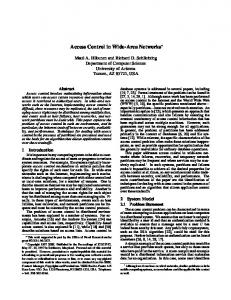
The 10 node network as shown in Figure 1 was chosen for study, primarily because of the large number of alternate paths to choose from when a call needed a path from any source node to any other destination node in the network. The main aim of this experirnerit was to compare the performance of various routing cost schemes defined above with the Minimum Ilelay (MD) scherqe of the IBM plaNET network. A detailed simulation rnodel of the network was implemented using SLAM. In the simulation model the capacit,y of each link is assumed to be one, and the packet size is assumed to be exponentially distributed with unit length; thus, the service rate of each link is one packet per second (pps). In the experiment, 50 virtual circuits between various origin-destination nodes were setup to bring the total load on the network to 13.075 pps (for details see [a]). We model the packet, arrival rate for each virtual circuit under normal conditions (before failure) as independent Poisson processes with fixed mean rate. We then simulate the failure of link 2-4 and study the congestion at node 9 mainly because of the topology of the network providing four different outgoing links for this node. Before the failure, nine virtual circuits originating from Node 9 were using link 2-4 and the total flow on the link 2-4 was 0.75. The input rates and the paths selected by the four rerouting schemes during the rerouting phase (after failure of 2-4) for the nine virtual circuits is given in the Table 1. From Table 1, one can see how the Minimum Iklay algorithm routes five virtual circuits along link 9-1 while two other virtual circuits are rerouted over link 9-7 and the remaining two use link 9-3 at the primary node. The Minimum Hop scheme tries to restrict the rerouting of the virtual circuits such that a rninimum number of secondary nodes are created. Thus, when the first virtual circuit gets rerouted along its minirnum hop path 9-1, all further reroutings tend to favor the same primary link. Hence, the minimum hop scherne routes eight virtual circuits along link 9-1, the rernaining one being routed along link 9-7. The Load Distribution algorithms try to spread out the rerouted calls among the paths in the network or among tjhe four outgoing links of node 9. Note tthat the algorithm for Load Distribution Among Paths routes the virtual circuits in such a fashion that all the outgoing links from Node 9 are utilized. It is found that all the paths chosen are three or four hop paths, four being the maximum allowed in the model setup. One (-an see that the algorithrn tends to favor the longest path with the maximum residual capacity. The algorithm for Load Distribution among Primary Links tends to reroute all the virtual circuits by spreading them out equally among all the outgoing links at Node 9. However, this algorithm does not seek to reduce or spread out the congestion among the other links in the network. Table 2 gives a comparative listing of the number of links at primary and secondary nodes that are used by t,he various schemes. It is seen that the Minimum Delay scheme routes the virtual circuits over three primary and eight secondary links. The Minimum Hop 1141
35.2-3
scheme tries to restrict the number of links used and results in 2 links at primary nodes and 5 links a t secondary nodes being utilized. Note that as expected the Load Distribution schemes result in the largest number of primary and secondary links. Table 2 also shows the number of links that were congested using the various schemes. The congestion in the network was studied by determining the number in the queueing system versus time for various links in the network using an ensemble average of 3000 simulation runs as discussed in [7]. A link was considered congested if the number in the queueing system at a link exceeded the steady state grade of service level. The steady state grade of service was determined by the link utilization threshold specified (85%), which resulted in a steady state grade of service number in systern of 5 ( see [2] and [4] for details). From Table 2 it is t,o be seen t,hat the MinimumHop scheme congests the least number of links while the Load Distribution among Paths scheme congests the largest number of links during the rerouting process. Looking a t the break up of primary and secondary links that are congested, the Minimum Hop scheme results in the fewest primary and secondary links congested. Figure 2 shows the number in the system versus t,ime a t link 9-1 after the link failure. From this figure, we see the amount of congestion that results from the rerouting of tjhe virtual circuits due to the four different, schemes. It is seen how the restrictive Minimum Hop scheme congests the link approximately 3000 seconds as opposed to the other schemes which congest the same link for a very short time (- 500 - 800 seconds) before reaching steady state. Similarly one can examine the other links in the network and Table 3 gives a comparative listing of the amount of time that each scherne congests a given link after rerouting. Note, as expected, the Load Distribution schemes do not, congest the network for as long a duratlion as the Minimum Hop scheme. Considering Tables 2 and 3 together, one can see the the following. The Minimum Hop Scheme resulted in fewest number of links becorning congested. However, it resulted in t,he largest time period of congestion. In contrast, the Load Distribution schemes resulted in a greater number of links becoming congested but for a much shorter time period. Hence, there is a clear trade off between constricting the region effected by congestion versus congesting a larger region for a possibly smaller arriount of time. Also, the performance of the Minirnuni Delay scheme was in between the Minimum Hop and Load Distribution schemes. In general t h r perforniancx of the Minimum Hop scheme as well as the Load Distribution schemes tend t,o depend on the net,work topology, the location of the failed link as well as the load in the network at tjhe t,ime of rerouting. Selecting which scheme is preferred will depend on the need to restrict the effects of failures locally to t,he region of the failure or the need to quickly recover from failures. Obviously, additional work needs to be conducted to precisely quantify the tradeoffs among the schemes. Also, since the Mininium Delay scheme is optirnal under steady state conditions, one may want tjo restructure the paths of the
35.2-4
virtual circuits after the congestion period is over
4
Summary
In this paper we have proposed alternate routing algorithms suitable for traffic restoration after a failure in a virtual circuit packet switched wide area network. Specifically, the Minimum Hop scheme - which ensures that the number of nodes directly effected by the rerouting is minimized, the Load Distribution Among Paths scheme - which picks the source-destination route that has the maximum residual capacity, and the Load Distribution among Primary Links scheme - which balances the load on the outgoing links of node that must reroute several connections. The relative transient performance of the routing algorithms (along with minimum delay routing) was studied using a simulation model of a 10 node sample network. It is shown that the routing algorithm used for traffic: restoration is an important criterion for controling the transient network congestion occurring after restorat,ion both spatially and in terms of duration.
Ref er en c es [ I ] A. Banerjea, (1:. J . Parris and D. Ferrari, “Recovering Guaranteed Performance Service Connections from Single and Multiple Faults,” Techriical Report TR-93-066, International Computer Science Institute, Berkeley, CA, 1993.
[“I
K. Balakrishnan, “An Analysis of Routing Strategies for Traffic Restoration in Wide Area Networks,” M.S.Thesis, Clemson IJniversity, 1992.
[3] K . Balakrishnan, D. Tipper and J. Harrimond, “An Analysis of the Timing of Traffic Restoration in Wide Area Communication Networks,” Proceedings of 14th I n teriia tiorial Teletrcific (;onyress, Antibes, France, 1994.
[4] I. Cidon, I. Gopal, and R. Gu6rin, “Bandwidth Management and Congestion Control in plaNET,” IEEE C o m m Mag.’ vol. 29( 10):59-64, C>c-tjoher 1991. [5] W. E, Falconer, “Service Assurance in Motlern Telecommunications Networks,” IEEE (:omm. Mag.,vol. 28(6):32-39, June 1990.
[SI J . Kobza, “The ,Significance of Traii.sient.s Follouiiug Failures a n d Repairs in Packet-,Suiitched Networks”. PhD thesis, Virginia Polyt,echnic- Inst,it,ut,e and State IJniversity, February 1993. [7] W. Lovegrove, J . Hammond, and D. Tipper, “Sirriulation Methods for Studying Nonstationary Behavior of Computer Networks,” IEEE Jrnl. ,Sel. Areas Coirim., vol. 8:1696-1708, 1990.
[8] D.Medhi and S.Sankarappan, “Impact of aTransmission Facility Link Failure on Dynamic Call Routing Circuit-Switched Networks under Various Circuit Layout Policies,” Jriil. of Net. (i11d h‘ys. LUgTrit.,Vol. 1, pp. 143-169, 1993. 1142
Table 1: Comparison of paths selected for rerouting
Tm8-
- ._ ,_ -
0.12 0.10 0.10 0.06 0.05 0.10 0.10 0.04
9- 1- 10-4 9-1-1 0-4 9-7-3-5 9-1-8-5 9-7-6-5-8 9-3-5-8 9-3-5-8-10 9-3-5-6
-
9-1-4 9-1-4 9-7-6-5 9-3-5 9-7-3-5-8 9-1-8 9-2-1-10 9-2-3-5-6
Table 2: Comparison of number of links used (congested) by the various schemes
Rerouting scheme MD MH LDAP LDPL
Primary Links used (congested)
3 2 4 4
(3) (2) 4 4
Secondary Links used (congested)
8 (5 5 (31 13 5 11 3
Total Links used (congested) -
11 (8) 7 (5) 17 (9 15 (7
Figure 1: Model 10 Node network
Table 3: Amount of time (seconds) for transient congestion to end
330
[9] D. Mitra and J. B. Seery, “(:omparative Evaluations of Randomized and Dynamic Routing Strategies for Circuit-Switched Networks,” IEEE Vol. 39, pp. 102-115, 1991. Trans. Co~ii~ri.,
7-3 3-5 1-10 10-4
[lo] D. Tipper, J. Hammond, S. Sharrna, A. Khetan, I