use of FIFO buffers to stream input data makes the design portable to other FPGA-based platforms with higher memory bandwith. Key words: Sparse Matrix ...
Row-interleaved streaming data flow implementation of Sparse Matrix Vector Multiplication in FPGA Branimir Dickov ∗† , Miquel Peric`as † , Nacho Navarro ∗† , and Eduard Ayguad´e ∗† †
Barcelona Supercomputing Center, Barcelona {branimir.dickov,miquel.pericas,nacho.navarro,eduard.ayguade}@bsc.es http://www.bsc.es ∗ Departament d’Arquitectura de Computadors, Universitat Polit`ecnica de Catalunya, Barcelona http://www.ac.upc.edu
Abstract. Sparse Matrix-Vector Multiplication (SMVM) is the critical computational kernel of many iterative solvers for systems of sparse linear equations. In this paper we propose an FPGA design for SMVM which interleaves CRS (Compressed Row Storage) format so that just a single floating point accumulator is needed, which simplifies control, avoids any idle clock cycles and sustains high throughput. For the evaluation of the proposed design we use a RASC RC 100 blade attached to a SGI Altix multiprocessor architecture. The limited memory bandwidth of this architecture heavily constraints the performance demonstrated. However, the use of FIFO buffers to stream input data makes the design portable to other FPGA-based platforms with higher memory bandwith. Key words: Sparse Matrix Vector Multiplication, Floating Point, FPGA, Compressed Row Storage
1
Introduction
As floating-point performance achievable on FPGA has risen beyond that of processors [1] the motivation for the science community to move computationally intensive kernels to FPGA and improve performance of scientific application has grown considerably. When computing SMVM, microprocessors have been shown to achieve very low floating point efficiency [2]. Compared to dense kernels, sparse kernels incur more overhead per non-zero matrix entry due to extra instructions and indirect, irregular memory accesses. Also, the large number of operands required per result and minimal reuse stress load/store units while floating point units are often under-utilized. In FPGA implementation, data structure interpretation is performed by spatial logic. Thus, by using streaming of data to/from memory and fully pipelined functional units, FPGA systems can obtain high levels of performance compared to their clock speeds. Current FPGAs contain many more configurable logic blocks which allows implementing
2
Dickov et al.
multiple copies of the same computations. Given the importance of the SMVM kernel, many early attempts to implement this algorithm on FPGAs exist. Zhuo [6] and Sun [7] both implemented an adder tree based design with an optimized reduction circuit that requires only a few floating point adders. These designs streamed the matrices using the Compressed Row Storage (CRS) format. However, this design creates complications in the accumulator circuitry as a new element to be accumulated is generated every cycle, far too much for a single floating point adder implemented in FPGA. In this paper we propose to overcome this problem by streaming the matrix in a row-interleaved variant of the CRS format for sparse matrix representation. By packing the matrix in this way independent dot products are interleaved on a single floating point adder, which can then implement the reduction all by itself. By using less logic resources for reduction circuit we achieve both power and area savings. As another important feature, our design doesn’t depend on the sparsity structure of the matrix or on the number of non zero elements per row. To evaluate these ideas we implemented the design using a binary adder tree with 4 leaves on a Virtex4 LX200 device present in a RASC RC100 blade of a SGI Altix machine. Test matrices for our design were created in software with completely random structure. Given the amount of Block RAMs (BRAM) present in the FPGA device, matrices cannot have more than 16,000 columns. Since rows of matrices are streamed one after another, no limitation exists on the number of rows. On the V4LX200 device, the algorithm requires up to 50% less slices than competing approaches. Running at 200MHz, a maximum troughput of 1.6 GFLOPS can be achieved, although this value is limited by the parameters of the platform. The rest of the paper is organized as follows. In Section 2 we introduce the SMVM algorithm used in this paper. We then elaborate on basic SMVM designs in FPGA and propose our design (Section 3). Implementation details on our target hardware are given in Section 4, while the design is evaluated in Section 5. Some additional related work is presented in Section 6 in the context of our design. Finally, we conclude the paper with some ideas for future work that can further improve the design.
2
SMVM Problem
Sparse matrix vector multiplication in the standard form y = Ax is one of the most time consuming computational kernels for iterative solvers of sparse linear systems such as Conjugate Gradient method (CG) [3]. The extra computations besides SMVM in CG are some vector parallel operations which are small compared to SMVM. Profiling PETSc’s [4] CG algorithm for the bi-laplacian stencil we obtain that more than 75 % of all computations are spent on SMVM. In general, the SMVM y=Ax is defined as: yi = Σ N j=0 ai,j xj , (0 ≤ i < M )
Row interleaved streaming data flow implementation of SMVM in FPGA
3
Where A is an M × N matrix, while y and x are M × 1 and N × 1 vectors, respectively. In general some kind of compressed storage that just saves non zero elements, such as Compressed Row Storage (CRS), is used to store sparse matrices. A square sparse matrix A with dimensions n × n and with m non zeros, is represented with three arrays in the CRS format: – rowID: Stores the starting index of the first non zero element of each row. Has the same length as the dimension of the matrix plus one n+1. – Col : Stores the column indices of non-zero elements. The length is the number of non-zeros m. – Val : Stores all non-zero elements in row major order. The size is the number of non-zeros m.
3
SMVM design in FPGA
In this paper we show an innovative SMVM design for FPGA. In order to do so we will first explain a design for pure CRS that is based on the works of Zhuo and Prasanna [6] and Sun and Peterson [7] which also serve as this work’s motivation. 3.1
SMVM design using CRS
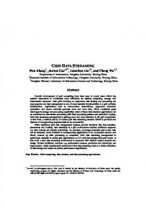
To achieve high frequency, floating point adders are usually deeply pipelined, which difficults accumulation of floating point data. To fully exploit computational throughput of the FPGA and avoid any idle cycles we want to pipeline the dot-product accumulation as heavily as possible. BRAM
len
BRAM
STREAM 0
X[col]
FIFO BRAM
X
fp_mult
reg
FIFO
A1 BRAM
STREAM 1
X[col]
FIFO
X
fp_add
reg
fp_mult
len(i)>0 no
reg
FIFO BRAM
yes
A1
STREAM 3
FIFO
BRAM
COL
X[col]
FIFO
X
fp_add
BRAM
fp_mult reg reg
FIFO
A2 STREAM 2
BRAM
X[col]
FIFO
X
reg fp_add fp_mult
reg
FIFO
A2
WRITE TO SRAM
Fig. 1. Complete SMVM design using CRS
On the front end of our design (Fig. 1) the binary tree with k leaves accepts data, every leaf contains one multiplier and BRAM in which the multiplicand
4
Dickov et al.
vector X is preloaded which is addressed by the Col vector. Obtained products are then accumulated by internal adders in the binary tree and finally one partial sum is produced every clock cycle. On the back end, the latency prevents us from pipelining partial results from adder tree so we need temporary storage (BRAM) with the same size as the latency of the adder, Ladd . Once the BRAM is full we employ a reduction circuit. The first part of the reduction circuit is an adder tree from which we obtain new partial sum. The partial sum is then passed to the adder which works like a back loop adder that provides us with a final result for the corresponding row. An improvement can be made in reduction circuit by using instead of the adder tree just a pipeline of adders with buffers [6] [7], (Fig. 2) where all circuit is driven just by data flow and without any control logic. When the first adder gives output, the value is passed through one buffer register in order that next adder start when both inputs are available. Adders at different levels will be used at different cycles producing finally one accumulated result. But in order to work for different matrices independently of number of non zeros per row one BRAM, size of vector X, has to be implemented as a temporary storage. BRAM
BRAM
RESULT
DOUT
Fig. 2. Reduction Circuit
3.2
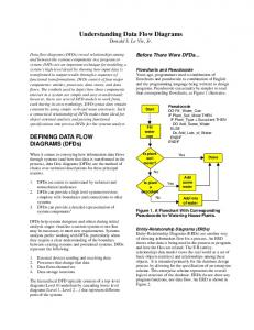
SMVM design with new interleaved CRS
In the new design, the front end is not changed but the back end is considerably simplified, (Fig. 3). As we mentioned adder latency Ladd prevents us from pipelining the partial result obtained from front end but we can interleave the independent partial result on a single floating point adder and achieve maximum throughput. Thus, adder latency Ladd becomes the interleaving factor. By modifying traditional CRS format on software side we achieve that after every Ladd cycles we get a new dot product that can be added to the last corresponding partial dot product. So the idea is to use a kind of window whose slots get filling with independent dot products (rows) of the matrix. The size of the window should be equal to Ladd to achieve paralelization due to pipelining. Every clock cycle k (on Fig. 3 k=4 ) elements of vector Val size of 64 bit and k elements of vector Col size of 16 bit are streamed respectively to multipliers and BRAMs in this new rescheduled CRS format. If the number of non zeros in a row is not multiple of the number of k we have to pad them with zeros. When some slot of the window is empty (there are no more elements in current row) this
Row interleaved streaming data flow implementation of SMVM in FPGA
5
slot is granted to next corresponding row. By doing this the throughput of the pipeline adder is sustained. As we see by using single floating point pipeline we can calculate dot product for every row without almost any idle clock cycles. At the end of the design due to different number of non zero elements in rows some bubbles have to be introduced in order to finish summation correctly. The bubbles are not introduced physically in the sense that they are streamed with non zeros. What happens is that when some element of vector Len is zero(there are no more non zero elements for that row and there are no new rows) and still some rows have to finish their accumulation, the reading from input FIFOs is stopped but multipliers and adder tree continue in order to deliver new elements to single adder loop at the correct cycle. LATENCY OF ADDER BRAM
len BRAM
STREAM 0
X[col]
FIFO BRAM
X
BRAM
FIFO
row index
fp_mult reg
BRAM
BUFFER
len_comp
FIFO
A1 BRAM
STREAM 1
X[col]
FIFO
X
reg fp_add reg
A1
STREAM 3
FIFO
BRAM
COL
X[col]
X
no
fp_mult
FIFO BRAM FIFO
len(i)>0
yes
reg
fp_add
fp_add fp_mult reg
FIFO
A2 STREAM 2
BRAM
FIFO
X[col]
X FIFO
reg fp_add fp_mult
reg WRITE TO SRAM
A2
Fig. 3. Complete SMVM design using rescheduled CRS
Because the time for accumulating a full row on the single pipeline adder depends on how many non zeros that row has, results will not get out in row major order. For example if row X has less than k non zero elements and first row has multiple number of non zeros, accumulation for row X will be finished in just one pass through adder pipeline. Thus, to have in every moment control and also to be sure that all non zeros are accumulated for some row, FSM with Ladd states is implemented. As was mentioned earlier about vector X also vector Len of CRS format are preloaded to FPGA BRAM before starting any computation. The FSM controls two arrays row index and len comp which have size of Ladd . The FSM and computation are started when “empty” signal of entry FIFOs is pulled to zero. In the row index array we keep the indexes of actual rows that are to be computed. len comp contains the corresponding number of elements that need to be computed to obtain final result. After every new k elements are feed to multiplier, vector len comp is updated. When value of vector len comp for corresponding row reaches 0 the row computation is completed and the result
6
Dickov et al.
is written to row index location in SRAM memory. To be sure that the flag for the corresponding row that indicates that the last elements of some row are sent to multipliers, a FIFO buffer is introduced so that the flag and result match up at the output of single adder pipeline. If the flag is not pulled up this means that there are still some non zeros in a row that have to be calculated so the output is back-looped. In Table 1. results for the total number of LUTs spent for adders and multipliers are shown for all three designs explained here. Table 1.Sum of LUTs used by floating point multiplier and adder Type of storage Number of LUTs Design of back end CRS format 24612 binary adder tree CRS format 10500 optimized reduction circuit Interleaved CRS format 6972 single floating point adder
4 4.1
Implementation details Targeted platform
Altix is Silicon Graphics’ line of servers and supercomputers based on Intel Itanium processors. In this work we target the ALTIX 4700 platform. The SGI Altix 4700 platform is comprised of modular blades: interchangeable compute, memory, I/O and special purpose blades for ’plug and solve’ configuration flexibility. Besides microprocessor nodes, it also features reconfigurable nodes named SGI RASC RC100 [9], (Fig. 4), which have 2 Virtex 4 XC4VLX200 FPGAs and 5× SRAM local memories for every FPGA. The peak transfer rate between host and RC 100 blade is provided as 3.2 GB/s in each direction. MEM
3.2 GB/sec
HOST
RC 100 FPGA
ITANIUM
FPGA
Fig. 4. RC100 blade on Altix 4700
4.2
CLB utilization and IP cores
The majority of logic is used for generation of mathematical operators. We used Xilinx IP cores which follow the IEEE 754 standard that can be customized for generation of mathematical operators and memories. For generation of mathematical operators we used DSP48 slices [10]. Virtex 4 XC4VLX200 has 96 DSP48 slices and for generation of floating point IP multipliers 16 DPS48 slices are used in “full usage” mode, so in the case where k =4 it’s possible to generate all multipliers with DSP48, and even to use DSP48 to create the adders. With respect a floating point adders using just logic doesn’t result in an important increase of slices while in case of multipliers this drastically change. In Table 2. main characteristics of the design are shown.
Row interleaved streaming data flow implementation of SMVM in FPGA
7
Table 2.Main characteristic of 64-bit SMVM design Total slices 22898(25%) BRAMs 311 (92%) Multiplier latency 22 Adder latency 10 Required I/O bandwidth 8 GB/sec Available I/O bandwidth 3.2 GB/sec Operation Frequency 200 MHz 4.3
BRAM
In the design we used 4 BRAMs for vector X whose length is n and width is of 64 bits. Also, 1 BRAM is used for vector Len with length of n and width of 32 bits. The Virtex-4 LX200 FPGA contains 336 BRAM units, each with the capacity of 18Kb. This yields an internal high speed memory capacity of 6,048 Kb = 756 KB. For example, for storing vector X of size of 16.000 in BRAM would require 125 KB. For the design to support SMVM with matrices of up to 16.000 rows, 311 BRAM units are needed which represents 92% usage of BRAM memory. Thus, we can see that this can be a limiting factor for the size of matrices that can be calculated using the FPGA implementation. If memory bandwidth increases, it would be even worst, as we would need more copies of vector X, which would lead to further reduction of the size of matrices in order to fit all vectors in BRAM.
5 5.1
Evaluation of proposed design Performance
In our design we have 8 fully pipelined floating point units, so with operation frequency at 200 MHz for this implementation we get peak floating point performance of 1.6 GFlops/sec. Considering that the available bandwith is 3.2 GB/sec and that design needs 8 GB/sec to reach peak performance we get that peak theoretical efficiency of our design can be: 3.2 GB/sec 8 GB/sec
= 0.4 ∗ 100% = 40%
Thus, peak floating point performance that can be achieved is: 1.6 GF lops ∗ 0.4 = 640 M F lops The area efficiency of our design is: 1.6 GF lops 22898 slice
≈ 0.07 M F lops/slice .
The idea of this work wasn’t to achieve any spectacular performance for ALTIX platform but to show that on another platforms with the reasonable good memory bandwith portability is preserve in order to achieve good performance with low slice usage.
8
5.2
Dickov et al.
Scalability of design
The implementation of this design is done with k=4, but to be in position to feed all multipliers with new data every cycle we need 8 GB/sec of memory bandwith. We need 4 non zeros form vector Val size of 64 bit and 4 elements from vector Col of 16 bit, in total 8B × 4 + 2B × 4 = 40B, which gives the needed memory bandwith of 8 GB/sec at 200MHz clock speed. In ALTIX platform for streaming, independently of how many streams we use, total rate remain 3.2GB/sec. The idea was to show that if memory bandwith increase our design can adopt, but also if it increase more that 8 GB/sec the implementation can be easily augmented by simple instantiations of more multipliers, adders and FIFOs in the front end but the overall design would stay the same.
6
Comparison with other designs for SMVM
We focus on three works that implemented SMVM on FPGA, that we consider the most relevant and novel. Some of them are meant to work iteratively by doing SMVM multiple times on FPGA with some other operations included in iterative solvers others just do SMVM and stream the result out. The great majority of them use CRS as a standard compressed format. Thus, we will try to stand out what could be the disadvantages of their designs. We start with the work of Zhuo and Prasanna [6] who designed an adder tree based SMVM implementation for double precision floating point where multiplicand vector X is preloaded into FPGA. Computation is done row by row where the row is divided into subrows. The length of subrows is equal to number of leaves k of front end binary tree. Zero padding is implemented when the number of non zeros is not multiple of k. They propose technique called merging in order to reduce the overhead that can result from zero padding. To accumulate all subrows they use reduction circuit that contains 7 floating point adders. By using just 7 adders they limit the number of non zeros per row that can be calculated to 27 × k. This means that matrices that have rows with more than 27 × k non zeros can not be calculated and that design needs to be modified. In contrast thanks to interleaving, our design accepts any input matrices with no hardware changes required with just one single pipeline adder as reduction circuit. Sun and Peterson [7] proposed Row Blocked CRS to represent sparse matrix. They use multiple processing elements PEs along with reduction circuit to perform the SMVM. PEs are basically multipliers with FIFOs for storing intermediate results. By implementing simple PEs instead of an adder tree, zero padding is avoided. For reduction circuit they proposed a similar circuit to [6] with one exception that circuit has one input from resulting BRAM which enables performing accumulation independently of the number of non zeros per row. They use 4 adders along with buffers in reduction circuit whereas the design presented here achieves reduction with just one simple pipeline adder. Because time spent on I/O is greater than time needed by reduction circuit to finish SMVM, reduction circuit is shared between PEs. In the case that larger bandwidth is available this can be bottleneck, in the sense that more reduction circuitry would need to
Row interleaved streaming data flow implementation of SMVM in FPGA
9
be implemented which can considerably increase number of slices used. The design of deLorimier and DeHon [8] computes iteratively Ai × X = Y and uses exclusively on-chip BRAM to hold all of the SMVM data in order to achieve big memory bandwidth. Here, the matrix is partition across multiples PEs. The number of dot products assigned to PE should be the size of latency of adder, Ladd to achieve parallelism due to pipelining. By scheduling parts of dot products in correct order parallelism is obtained and any stalls are avoided. To achieve good efficiency all PEs should get approximately same number of non zeros. At the end of computation, some slots can not be fed and some bubbles have to be introduced. This design is very similar to ours in the sense that both reschedule the rows in order to achieve parallelism and avoid any stalls. The difference is that in our design rescheduling is done for all non zero values of matrix in such a way that when there are no more non zeros in a window slot a new row with its non zeros is introduced to that slot. By this we will have just some bubbles at the end and not at every partition part of design. Also in our design all accumulation is done on single floating point adder while they are using one adder for every PEs. Also due to the fact that all SMVM data resides inside the FPGA before computation starts these extra bubbles can affect the size of BRAM used. In contrast, in our case instead of putting all SMVM data on FPGA we just stream vectors Val and X inside the FPGA.
7
Future Work
For future implementations we believe it is necessary to further improve the design by overcoming the space limitations due to multiple instances of the X vector. This will be particularly important for higher bandwidths, as in this case even more copies of the vector will need to be stored. To reduce the storage required by X we want to study the possibility of distributing a single copy of the vector across several multi-ported memory banks. Each bank will then hold a subset of the vector and can be accessed independently. In order for this to work, the elements of the rows will need to be scheduled so to avoid conflicts when too many multipliers want to access X vector elements that reside in the same bank. Row elements can be rearranged and reordered for this to happen. Although it might not always be possible to find row elements that avoid access conflicts, and thus performance may slightly degrade, the possibility of storing a single copy of vector X in the FPGA would have obvious advantages both in terms of matrix size and as well as area efficiency. Thus we consider it worth to take a look at this optimization. The area reduction, for instance, would simplify the possibility of integrating the SMVM design together with a complete conjugate gradient implementation.
8
Conclusions
In this paper we haved developed a design for interleaved CRS. We show how using this new arrangement we can reduce the number of slices of the imple-
10
Dickov et al.
mentation. As a consequence, both the area and power efficiency of the design are improved. The design does not need to be changed for different matrices and overall performance just depends on the total number of non zeros of the matrix. One of the goals of the design is portability to other FPGA-based platforms with higher I/O bandwidth. Also, the overall scalability of the design is preserved by using a k binary tree structure in the front end. Based on our experience implementing this design we identify the size of the on-chip memory as an important bottleneck as it limits the size of the matrices that can be computed. Thus our further efforts will concentrate on trying to solve this issue.
9
Acknowledgements
This work is supported by the Spanish Ministry of Science and Innovation (contracts no. TIN2007-60625 and CSD2007-00050) and the European Commission in the context of the HiPEAC Network of Excellence (contract no. IST-004408). Branimir Dickov is supported by Catalan Government with Pre-doctoral scholarship FI (reference no. 2009FI-B00077).
References 1. Underwood, K.: FPGAs vs. CPUs: Trends in Peak Floating-Point Performance. In Proceedings of the International Symposium on Field-Programmable Gate Arrays, pp 171–180, (2004). 2. Vuduc, R.: Automatic performance tuning of sparse matrix kernels. PhD thesis, University of California, Berkeley, Berkeley, CA, USA, December 2003. 3. Shewchuk, J.: An Introduction to the conjugate Gradient Method Without Agonizing Pain. School of Computer Science, Carnegie Mellon University (1994) 4. Portable, Extensible Toolkit for Scientific Computation, http://www.mcs.anl.gov/ petsc/petsc-2/, Argonne National Laboratory, Illinois, Chicago, United States 5. Barrett, R.: Templates for the solution of Linear Systems: Building Blocks for Iterative methods, 2nd Edition. SLAM , Philadelphia, PA (1994) 6. Zhou, L., Prassana, V.: Sparse Matrix-Vector Multiplication on FPGAs. Proceedings of the 2005 ACM/SIGDA 13th International Symposium on the FieldProgrammable Gate Arrays, pp 63–74, Monterey, California, USA (2005) 7. Sun, J., Peterson, G., Storaasli, O.:Mapping Sparse Matrix-Vector Multiplication on FPGAs.Proceedings of the Third Annual Reconfigurable Systems Summer Institute, NCSA, Urbana IL, USA, 2007 8. De Lorimier, M., De Hon, A.: Floating-point Sparse matrix-vector Multiply for FPGAs. Proceedings of the 2005 ACM/SIGDA 13th International Symposium on the Field-Programmable Gate Arrays, pp 75-85, Monterey, California, USA (2005) 9. Reconfigurable Application-Specific Computing User’s Guide, http://techpubs. sgi.com, SGI (2008) 10. Xilinx, Inc. http://www.xilinx.com