RTL Semantics and Methodology Brian Bailey
Dan Gajski
Mentor Graphics Corp. Wilsonville, OR 97070
[email protected]
University of California Irvine, CA 92697
[email protected] and we finish up with languages that are open to interpretation and in some cases unpredictable results. What makes matters worse is that in most cases, the language is designed for one task and used for another, which causes the community to sub-set the language to one suitable for the second task. In these cases it is usually found that the semantics are not clear enough to define the outcome required in the second task which makes tools unpredictable and difficult to obtain consistent results from. Within the EDA community we have seen this happening on too many occasions already and it has cost all parts of the community a lot of time and effort. This paper is intended to relate RTL theory and practice with RTL modeling and synthesis/simulation issues. With a firm foundation it will become possible to start defining the semantics needed in higher level languages. RTL semantics must be based on simple implementable models. Semantics defines what an RTL model means, which in turn is defined by how RTL design is implemented. In this paper we start with a generic RTL building block, called an RTL processor, and then describe how to build the systems out of these RTL processors. This way we can define semantics for RTL modeling, simulation, and synthesis.
ABSTRACT In the past, the EDA industry and designers have struggled with the issues of having multiple languages in use for describing, implementing and verifying their designs, such as Verilog and VHDL. This has led to gross inefficiencies in the industry with tool vendors needing to support multiple languages, which are often dissimilar, and in some cases contradictory, and with users having to deal with incompatible library issues. With the industry embarking on the search for new system level languages we already have several languages based on C or C++ that are emerging and the distinct possibility is arising that we will again be faced with language “wars”. In order to prevent this we need to ensure a minimum level of compatibility between them so that it can guaranteed that information could be moved from one language to another without loss of information. It is for this reason that an Accellera working group was formed with the intention of creating a standardized set of semantics that can be shared between all of the language organization. This paper will take a look at the progress made by the group and its results to date.
Categories and Subject Descriptors
2. RTL PROCESSOR
D.3.3 [Programming Languages]: Language Semantics for the RTL level
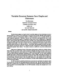
In order to define the RTL design flow we first define the RTL processor model. Such a model consists of a controller and a datapath. As shown in Figure 1, the model has two types of I/O ports. One type of I/O ports are data ports, which are used by the outside environment to send and receive data to and from the model. The other type of I/O ports are control ports, which are used by the outside environment to receive the information about the status of the model and to send the information about the status of the environment.
General Terms Standardization, Languages, Theory.
Keywords Accellera, RTL semantics, FSMD, RTL processor
1. INTRODUCTION
The datapath consist of storage units such as registers, register files, and memories, and combinatorial units such as ALUs, multipliers, shifters, and comparators. These units and their input and output ports are connected by buses. The datapath takes the operand from storage units or input ports, performs the computation in the combinatorial units, and returns the results to storage units or output ports during each state, which is usually equal to one clock cycle.
Creating a language is easy. You just need to throw together some syntax and voila, there you have it. However, there are two problems with this. The first issue is: does the language solve a useful task? We will not be addressing this subject in this paper. The second issue is: does everyone who reads your new language know what it is meant to do under all circumstances? If the answer to this is ‘yes’, then it probably means that you have designed the language based on a well defined semantic foundation. Unfortunately in most cases the answer to this is ‘no’
The selection of operands, operations, and the destination of the result are controlled by the control unit by setting proper values of the datapath control signals. The datapath also indicates, through status signals, when a particular value is stored in a particular storage unit or when a particular relation between two data values stored in the datapath is satisfied. The input ports can be connected directly to register or storage units or to any other component in the datapath including the output ports. The output ports could be used for possible connections to other RTL
Permission to make digital or hard copies of all or part of this work for personal or classroom use is granted without fee provided that copies are not made or distributed for profit or commercial advantage and that copies bear this notice and the full citation on the first page. To copy otherwise, or republish, to post on servers or to redistribute to lists, requires prior specific permission and/or a fee. ISSS’01, October 1-3, 2001, Montréal, Québec, Canada. Copyright 2001 ACM 1-58113-418-5/01/00010…$5.00.
69 75
processors through outside buses or directly through point-topoint connection. Control
Datapath
inputs
inputs
Start =0
signals Status
unit
signals
Control
S1
Data = Inport
S2
Ocount = 0
S3
Mask = 1
S4
Temp = Data AND Mask
S5
Ocount = Ocount + Temp
S6
Data = Data >> 1
S7
Done = 1: Outport = Ocount
Datapath
Datapath outputs
outputs
Done = 0; Outport = X
Start = 1
Control Control
S0
High-level block diagram FIGURE 1.
RTL Processor
Similar to the datapath, a controller has a set of input and a set of output signals. There are two types of input control signals: external signals and status signals. External signals represent the conditions in the external environment on which the model must respond. The Start signal in the one’s counter example shown in Figure 2, which starts the one’s counter, is such an input signal. On the other hand, the status signals represent the state of the datapath. Their value is obtained by comparing values of selected variables stored in the datapath. For example, Data = 0 in the one’s counter example is such a signal whose value is equal to 1 when the value of Data is equal to 0 and 0 when the value of Data is not equal to 0.
Data ≠ 0
Data = 0
State diagram
There are also two types of output control signals: datapath control signals and external signals. The control signals select the operation for each component in the datapath, while the external signals identify to the environment that the model has reached a certain state or finished a particular computation.
FIGURE 2. One’s counter specification
3. FSMD DEFINITION In Section 2, we discussed in general terms the RTL processor model. In this section we discuss how to specify its functionality. We will introduce it on the example of one’s counter, which counts the number of 1’s in the word presented at the Inport as shown in Figure 2.
A controller consists of a state register and next-state and output logic. Next-state logic generates the value for the state register in the next clock cycle while output logic generates the value of control and external signals. Each RTL processor follows this general architecture, although two RTL processors may differ in the number and type of control units and datapaths, the number of components and connections in the datapath, the number of states in the control unit, and the number and type of I/O ports.
The one’s counter is specified by an FSM, representing the control unit and a set of variable assignments representing register transfers in the datapath. The FSM has eight states and transitions from one state to another under the control of the external signal Start and the status signal (Data = 0). In each state the FSM assigns values to a set of datapath variables. A variable assignment statement gives an expression to be used for computation of the new variable value. In each state and for each variable assignment associated with that state the datapath evaluates the expression on the right-hand side of the assignment and assigns it to the variable on the left-hand side of the assignment. Generalizing from the one’s counter specification, we may say that an FSM model with assignment statements added to each state, called an FSM with data, or FSMD, (reference 2) can completely specify the behavior of an arbitrary RTL processor.
An RTL processor may also be pipelined in several different ways: (a) By inserting latches or registers on control signals and/or status signals, we obtain pipelined control. (b) The datapath can also be pipelined by inserting latches or registers on selected connections, such as after storage elements, before functional units, and after functional units. (c) Each function unit can be pipeline by dividing it into several stages and inserting latches between the stages.
70 76
STATE UNMAPPED RTL TRANSITIONS (STYLE 1)
a=d*e b = f+(
)
c=... S1
STORAGE MAPPED RTL (STYLE 2)
FUNCTION MAPPED RTL (STYLE 3)
CONNECTION MAPPED RTL (STYLE 4)
EXPOSED STRUCTURAL CONTROL RTL RTL (STYLE 5)
r1 = f* (r1,M(0))
r1 = FU2(*,r1,M(0))
Bus1 = r1
C1 = 1
r2 = f+ (. . .)
r2 = . . .
Bus2 = M(0)
C2 = 0
M(0) = . . .
M(0) = . . .
Bus3 = FU2(*,Bus1,Bus2) C3 = 1
f3(a,b,c)
r1 = Bus3
C4 = 0
...
C5 = 1 C6 = X C7 = 0 C8 = 0 C9 = 0
S2
d = f4 (a,b)
r1 = . . .
r1 = . . .
e = f5 (c,d,e)
M(0) = . . .
M(0) = . . .
f=a-b
r1 = f-(r1, r2)
r1 = FU1(-,r1,r2)
Bus1 = r1
C1 = 1
g = f#(. . .)
r2 = . . .
M(1) = r1
Bus2 = r2
C2 = 1
h=...
M(1) = . . .
Bus3 = FU1 (-,Bus1,Bus2) C3 = 0
S3
r1 = Bus3
C4 = 1
...
C5 = 0 C6 = 1 C7 = X ...
S4
MAPPINGS
i=...
M(2) = . . .
M(2) = . . .
j=...
r2 = . . .
r2 = . . .
k=...
r1 = . . .
r1 = . . .
Storage mappings Function mappings
Connection mappings
Control mappings
{a,d,f,k} = r1
{f-, f+} = FU1
r1_to_FU1L = Bus1
r1_to_Bus1 = C1
{b,h,j} = r2
{f*, f#} = FU2
r1_to_FU2L = Bus1
r2_to_Bus2 = C2
{c,e} = M(0)
{f3,f4,f5} = FU3
r2_to_FU1R = Bus2
M_to_Bus2 = C3
{g} = M(1)
...
M(0)_to_FU2R = Bus2
FU1_to_Bus3 = C4
{i} = M(2)
FU1_to_r1 = Bus3
FU2_to_Bus3 = C5
...
FU2_to_r1 = Bus3
FU1 = C6
...
FU2 = C7 M(address) = C8 M(read/write) = C9
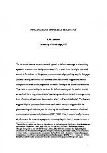
State diagram with different levels and mappings FIGURE 3. An incomplete example 71 77
are grouped and assigned to storage units. In other words, a group of internal variables is replaced by a new variable of type storage.
From our FSMD we see that in each state we compute the next state which depends on some condition from the outside environment or on some status signal computed from values of FSMD variables. The FSMD definition also allows assignment of values to any variable in each state. However, variables and functions in the definition of FSMD may have different interpretations which in turn defines several different styles of RTL semantics.
In our example in Figure 3, we grouped variables a, d, f and k and assigned them to register r1 while b, h, and j were assigned to register r2. Similarly variables c and e were assigned to memory location M(0) while g and i to memory locations M(1) and M(2). This assignment is shown in storage mapping table at the bottom of Style 1 in Figure 3. Note, that in Style 2 we used functional notation for all the operators for uniformity sake.
Figure 3 shows five different RTL styles for a 4-state segment of a FSMD definition and necessary mappings to arrive at that particular style.
Function-mapped RTL (Style 3)
Unmapped RTL (Style 1)
In Function-mapped RTL, the operators and/or functions with non-overlapping lifetimes are grouped into functional units, and a control encoding is assigned to each operation in the functional unit. Therefore, in Style 3 we must identify the operation performed by each function unit in each state. Style 3 is the same as Style 2 with functions replaced by multi-operation functional units. Note, that original functions and functions representing functional units use the same syntax.
In the Unmapped RTL the variables are divided into ports and internal variables, while ports are further divided into control and data ports, where each could be an input, output or input-output port. Unmapped RTL only specifies in each state the change of values for the variables. The order in which assignments are executed is determined by control dependencies, that is, the order written in the description. States, transitions and assignment statements are in no way related to any implementation. The variables do not represent registers or busses and functions or operations do not represent any functional units.
As we see in Function mapping table in Figure 3, we have three functional units: FU1 performing addition and subtraction, FU2 performing multiplication and operation #, and FU3 performing functions f3, f4, and f5. Thus, in Style 3 in Figure 3 the operators and functions are replaced by functions performed by functional units FU1, FU2, and FU3. If a functional unit needs more than one state to generate result then its input must be the stable through all the states while its output is loaded only in the last state. Functional unit may have several outputs, each of which must be clearly declared when assigning a new value to a variable.
The Unmapped RTL is equivalent to the programming language code with the exception that such code is divided into states, with conditional transition between states added to the code. For example, we see several assignment statements in each state in Figure 3. All statements assign values to uninterpreted variables. The values are computed by using standard language operators or functions if values require more complex computation. It is assumed that each operator or a function is computed in one clock cycle or less.
Connection-mapped RTL (Style 4)
Mapped RTL
Similarly to Style 2, the variables, with non-overlapping life times, that represent wires as well as inputs and outputs to and from storage elements and functional units are grouped and assigned to busses. Syntactically, there is no difference between wires and buses. The only difference is in additional bus drivers that must be inserted in Style 5. Similarly, we can merge (multiplex) ports if they are not used at the same time. We see from the Connection mapping table in Figure 3, that connections from register r1 to FU1 and FU2 are assigned to Bus1, connections from register r2 to FU1 and memory M to FU2 to Bus2, while connections from FU1 and FU2 to register r1 are assigned to Bus3. The refinement from Style 3 to Style 4 is similar to compiling a programming language into assembly language. Each assignment statement is decomposed into statements representing transfers from storage elements to functional units, functional units operation, and transfers back from functional units to storage elements. For demonstration
In the mapped RTL, the uninterpreted variables are mapped into storage units or wires/buses and computing functions or operators are assigned to functional units. Although this mapping can be performed in any order, it is convenient to map variables into storage first, followed by function mapping and then mapping of wires to buses. In this way, we can define three styles of mapped RTL. Storage-mapped RTL (Style 2) The variables in Style 1 can be of two types. One type is variables whose value is used in the same state in which that value is assigned. These variables represent wires. The other type is variables whose values are assigned in one state and used in the other state. The states between the value assignment and its last usage define the lifetime of each variable. These variables must be mapped to storage units such as register, register files, and memories. Thus, storage-mapped RTL is a RTL description in which the second type of variables with non-overlapping lifetimes
72 78
purposes, this decomposition is performed only for the first assignment statement in states S1 and S3 in Figure 3.
4. COMMUNICATING FSMDs As we defined in the previous section, each FSMD is uniquely defined by a set of ports and a description in any of the styles 1-5. The ports are defined by name: type, data, size, and attributes. Type is usually Boolean, bit-vector, integer, floating-point, character or other user defined type.
Exposed-control RTL (Style 5) In Exposed-control RTL, the FSMD model consists of two parts: a netlist of datapath components and a controller that assign a constant to each control variable in each state. The control variables specify the operation of each storage, functional or bus component in the datapath. Control mappings to perform the Style 4 assignments in Figure 3 are shown in the control mapping table. Thus, the transfers and operations are replaced by assignments to control signals for all storage, functional and bus units. The Style 5 column shows the control assignments for two statements given in Style 4. In addition, the partial design corresponding to these two statements is shown in Figure 4.
Attributes may include electrical, mechanical, simulation, test and synthesis requirements or metrics. The two necessary attributes for synthesis are setup and hold time for the input ports and delay time for the output ports. It is not possible to synthesize a design in which an RTL processor is a component without these timing attributes for ports. With such attributes included in the FSMD model we can combine two or more FSMDs into communicating FSMDs. The input ports can be connected to any component inside the datapath and output port can also be driven by any component in the datapath.
The datapath netlist consists of declared components (storage, functional and connection) and two types of variable assignments, component ports. The datapath netlist consists of declared components (storage, functional and connection) and two types of variable assignments, component ports to wires or buses, and buses to ports. Note that more than two ports, can be assigned to each bus, but not in the same state. This situation requires that each port has a tristate driver that is allowed to drive the bus when its corresponding control signal is asserted. Similarly, two or more buses can be assigned to the same port requiring insertion of a selector. Such a selector (multiplexer) is controlled by corresponding control signal from the controller.
In such a structure of communicating FSMDs, any output ports can be connected to any input ports as long as the type, size, and attributes match or connection is unambiguously specified for non-matching ports. Note that the above definition allows a dataport to be connected to a control port and vice versa. The communicating FSMDs may be driven by the same clock signal or different clock signals. In the first case, the delay time of an output port, the setup time of the input port, and delay of the connecting wires must be less than the clock period in case of
M(0)
C8 r1
M(1)
C9
r2
M(2)
C1
Bus1 C2
C6
+/-
FU1
C4
C3
C7
∗/# C5
Partial design FIGURE 4. An incomplete example
73 79
Bus2
FU2 Bus3
state-based FSMDs. Otherwise, the delay for any register to register transfer even through several FSMD, must be less than a clock cycle. In the second case, we must make sure that two FSMDs are synchronized during data exchange if the clocks are not multiples of each other. If they are, then the rules for FSMDs with the same clock apply.
6. Conclusions This paper presented some basic concepts of RTL design and attempted to explain the RTL methodology. It is the purpose of this paper to familiarize readers with the basic concepts explaining the pros and cons behind the devices and to serve as the accompanying document for the more complete specification for the RTL semantics standard. For details see Reference 1.
In the case of two FSMDs with different clock signals (or two input-based FSMDs) we can synchronize the data exchange by using protocol with Ready and Ack signals. Such a protocol, in essence, transforms two input-based FSMDs into two state-based FSMDs for the duration of two states during data exchange, and thus interrupts the feedback loop.
7. Acknowledgements The authors would like to thank all the members of the Accellera working group who contributed their time and assistance to improve the quality of this standard.
5. Hierarchical FSMDs The definition of an FSMD in section 3 allows for hierarchical composition of FSMDs. Each FSMD can be a component in another FSMD. In other words, an FSMD may implement an arbitrary functional unit or a storage unit. These component FSMDs may need a fixed number of states to finish. In the case of a FIFO, an output may be used only after a fixed number of states. In other cases the component FSMD may be synchronized with the controller by the use of Start and Done signals. The controller asserts the Start signal when the data at the input port is valid and the component FSMD asserts the Done signal when it is finished so that the data at its output port can be used. In case the component and composite FSMDs run at different clock cycle then synchronization with Start and Done signals must be used. Any number of FSMDs can be combined together in serial or parallel way to form larger FSMDs.
8. References [1] Accellera proposed standard http://www.eda.org/alc-cwg [2] Gajski, Dutt, Wu, Lin; “High-Level Synthesis,” Kluwer Academic Publishers,1992
[3] John F. Wakerly; “Digital Design: Pronciples and Practice,” Prentice Hall, 2000
[4] Randy H. Katz; “Contemporary Logic Design,” Benjamin/Cummings, 1994
[5] Daniel Gajski; “Principles of Digital Design,” Prentice Hall, 1997
74 80