¨ INFORMATIK INSTITUT FUR
Run-time Architecture Models for Dynamic Adaptation and Evolution of Cloud Applications Robert Heinrich Eric Schmieders Reiner Jung Willhelm Hasselbring Andreas Metzger Klaus Pohl Ralf Reussner Bericht Nr. 1503 April 2015 ISSN 2192-6247
¨ CHRISTIAN-ALBRECHTS-UNIVERSITAT ZU KIEL
Run-time Architecture Models for Dynamic Adaptation and Evolution of Cloud Applications Robert Heinrich1 Eric Schmieders2 Reiner Jung3 Willhelm Hasselbring3 Andreas Metzger2 Klaus Pohl2 Ralf Reussner1 April 20, 2015
1
Software Design and Quality, Karlsruhe Institut of Technology 2 Software Systems Engineering, University of Duisburg-Essen 3 Software Engineering Group, Kiel University
˚
˚
This work was supported by the DFG (German Research Foundation) under the Priority Program SPP 1593: Design For Future – Managed Software Evolution [GRG` 14] (grants HA 2038/4-1, RE 1674/7-1, PO 607/3-1) and the Helmholtz Association of German Research Centers.
Cloud applications are subject to continuous change due to modifications of the software application itself and, in particular, its environment. To manage changes, cloud-based systems provide diverse self-adaptation mechanisms based on run-time models. Observed run-time models are means for leveraging self-adaption, however, are hard to apply during software evolution as they are usually too detailed for comprehension by humans. In this paper, we propose iObserve, an approach to cloud-based system adaptation and evolution through run-time observation and continuous quality analysis. With iObserve, run-time adaptation and evolution are two mutual, interwoven activities that influence each other. Central to iObserve is (a) the specification of the correspondence between observation results and design models, and (b) their use in both adaptation and evolution. Run-time observation data is promoted to meaningful values mapped to design models, thereby continuously updating and calibrating those design models during run-time while keeping the models comprehendible by humans. This engineering approach allows for automated adaptation at run-time and simultaneously supports software evolution. Model-driven software engineering is employed for various purposes such as monitoring instrumentation and model transformation. We report on the experimental evaluation of this approach in lab experiments using the CoCoME benchmark deployed on an OpenStack cloud.
Contents 1 Introduction
4
2 Overview of the iObserve Approach 2.1 Phases of iObserve . . . . . . . . . . . . . . . . . . . . . . . . . . . . . . 2.2 Dynamic Change at Run-time . . . . . . . . . . . . . . . . . . . . . . . .
6 6 8
3 Run-time Analysis in iObserve 3.1 Terms and Definitions . . . . . . . . . . . . . . . . . . . . . 3.2 iObserve Mega Model . . . . . . . . . . . . . . . . . . . . . 3.3 Run-time Architecture Meta-Models . . . . . . . . . . . . . 3.4 Model-driven Monitoring . . . . . . . . . . . . . . . . . . . 3.5 Technology-Independent Record Specification . . . . . . . . 3.6 Point cut and Advice . . . . . . . . . . . . . . . . . . . . . . 3.7 Run-time Architecture Correspondence Meta-Model (RAC) 3.8 Transformations in iObserve . . . . . . . . . . . . . . . . . .
. . . . . . . .
. . . . . . . .
. . . . . . . .
. . . . . . . .
. . . . . . . .
. . . . . . . .
. . . . . . . .
10 10 12 13 14 15 18 19 20
4 Evaluation 4.1 Application Example 4.2 Research Questions . 4.3 Experiment Setting . 4.4 Experiment Results .
. . . .
. . . .
. . . .
. . . .
. . . .
. . . .
. . . .
24 24 25 26 28
. . . .
. . . .
. . . .
. . . .
. . . .
. . . .
. . . .
. . . .
. . . .
. . . .
. . . .
. . . .
. . . .
. . . .
. . . .
. . . .
. . . .
. . . .
. . . .
. . . .
. . . .
. . . .
5 Related Work
32
6 Conclusion
34
3
1 Introduction Cloud applications are subject to continuous changes during their operation. Examples include changes imposed by new or changed requirements, changes of the cloud infrastructures which may impact on application quality, as well as changes of application workload. While changes in cloud application requirements provoke manual software evolution activities, changes in cloud infrastructures (such as virtual machine migration and data replication) and application workloads may be addressed by the application in a self-adaptive way (e.g. see [BCD` 12, CWM` 14]). In this paper, we understand evolution as a longer sequence of modifications to a software system over its life-time applied manually by software engineers, while we understand adaptation (aka. self-adaptation) to be modifications of the software system performed in an automated way (cf. [PPPM10, MD12]). Both evolution and adaptation activities are required to address the different kinds of changes imposed on cloud applications. Run-time models have been established as a core concept for enabling adaptation by reflecting the system and its context at run-time (e.g. [MBJ` 09, RGH` 06]). Runtime models are up-to-date abstractions of the running system. Semantic relationships between run-time models and the executed systems are maintained, thereby allowing analyzing and planning adaptations on the model-level. Existing run-time model approaches only cover a very limited range of structural changes. However, updating run-time models to reflect structural changes is relevant, as the concrete component structures and deployment affect important application quality characteristics, such as performance and privacy. Changes of the cloud infrastructure, such as migration and replication of virtual machines and components, impact on the architecture and deployment of cloud applications. Due to the dynamic nature of such replications and migrations, the actual, concrete changes to the deployment of cloud services are not known at design-time. Therefore, structural changes in the cloud need to be monitored and run-time models for cloud applications have to be updated accordingly. Only if those changes are reflected in run-time models, their impact on application quality can be analyzed and adaptation actions can be planned if quality requirements are violated. While run-time models have shown their effectiveness for self-adaptation, using runtime models during software evolution has not been explicitly addressed. As commonly observed, design-time models often drift away from the actual system [MNS01]. In contrast, run-time models are kept in-sync with the underlying system. Thus run-time models may serve as valuable basis for evolution activities. However, typical runtime models are close to an implementation level of abstraction [VG10]. While being useful for self-adaptation, such low level of abstraction impedes understandability for humans. In addition, owing to various modifications during the system’s lifetime, runtime models may grow in detail or become unnecessarily complex, which severely limits
4
understandability of such run-time models for humans during software evolution (e.g. see [VG14]). To address the aforementioned shortcomings, we present the iObserve approach (Integrated Observation and Modeling to Support Adaptation and Evolution of Software Systems). The iObserve approach facilitates automated adaptation of cloud applications at run-time, while simultaneously supporting long-term software evolution. The initial idea of the approach has been presented in [HSJ` 14]. This paper underpins the initial idea by formal concepts, addresses underlying challenges, adds the description of detailed meta-models and model-transformations, as well as evaluation results. We provide the following main contributions: • Architectural run-time models, which reflect updates of component structures and deployments due to structural changes in the cloud. • Instrumentation models, which facilitate model-driven instrumentation and monitoring of cloud applications and infrastructures. • Correspondence models, which define the transformations between low-level monitoring data and component-based architecture models, thereby maintaining the semantic relationships between the system and the run-time models, while keeping the models understandable by humans. • Integrated model-driven engineering life-cycle, which supports software engineers during software evolution with always up-to-date models and facilitating runtime analysis with respect to quality attributes such as performance and privacy. • An evaluation of the iObserve approach using the CoCoME benchmark [RRMP08] deployed on an OpenStack cloud.1 The remainder of the paper is structured as follows. In Chapter 2, we present an overview of the iObserve approach. As major part of this paper, iObserve’s methods and techniques to run-time analysis are presented in Chapter 3. We report on the experimental evaluation of these methods and techniques in Chapter 4 and discuss related work in Chapter 5 before the paper concludes in Chapter 6.
1 http://www.openstack.org/
5
2 Overview of the iObserve Approach The cloud application life-cycle, underlying our iObserve approach, considers evolution and adaptation as two mutual, interwoven processes that influence each other [HHJ` 13]. The evolution activities are conducted by software engineers, while the adaption activities are automatically performed by predefined strategies. Figure 2.1 gives an overview of iObserve. During design-time, iObserve builds upon a model driven engineering approach (MDE) that, firstly, models the software architecture and deployment of the application in a component-oriented fashion and, secondly, generates the artifacts to be executed during run-time. Once deployed, the application is continuously monitored, which is required to update the run-time model in accordance to observed elasticity events. Central to this perception is a run-time architecture model, updated by monitoring data, that is usable for automatized adaptation and is simultaneously comprehensible for humans during evolution.
2.1 Phases of iObserve First, we give an overview and explain the three phases of iObserve addressed in the cloud application life-cycle. • Initial software development: Prior to run-time analysis and software evolution the initial software has to be developed. As we require an initial version of the application, we propose to follow an MDE approach that provides iObserve with models of the application’s usage profile, the application structure, and the deployment. Once the application is modeled typical source code artifacts such as class stubs are generated and their correspondence to design artifacts is recorded. Further, we generate the monitoring probes based on the model, which facilitates an automatized mapping between the model, the classes, and the monitoring probes. After completing the class stubs the application is deployed. • Run-time analysis: After the application has been deployed, iObserve continuously observes changes to the application and its execution environment and analyses for anomalies and upcoming quality flaws. The activities of the adaptation cycle are structured along the well-known MAPE-activities [dLGM` 13]. We monitor component migration, (de-)replication, (de-)allocation, resizing of virtual machines as well as changes in application’s usage intensity and user behavior (cf. the Monitoring&Observation phase in Figure 2.1), which maps to the run-time changes described in Section 2.2. After preprocessing the observed lowlevel events, we use the aggregated events to update the run-time architecture
6
Analysis Planning
Evaluation
Adaptation
Evolution Monitoring & Observation
Execution
Realization
Figure 2.1: iObserve cloud application life-cycle: Considering adaptation and evolution as two interwoven processes model and provide the updated model to the analyses. Immediately after updating the run-time architecture model, the quality analysis starts, which checks the application’s achievement of performance and privacy goals (cf. the Analysis phase in Figure 2.1). Both are key factors of modern cloud environments, as further discussed in Section 2.2. In case of impending privacy or performance issues, iObserve executes planning routines (not further discussed in the present paper). However, the planning routines either solve the detected issues or notify our approach that the encountered issues cannot be solved by any combination of adaptation actions available. In the latter case, software evolution is triggered. • Software evolution: Once entering the evolution cycle it has to be analyzed why the current system configuration fails in achieving the performance and privacy goals (cf. the Evaluation phase in Figure 2.1). In our work we focus on the application and its deployment (and do not reflect the adaptation capabilities). During this activity, we support the software developer by providing the up-todate run-time architecture model of the application that includes information on the application components as well as on their deployment contexts, i.e. PaaS or IaaS (the model does not reflect the adaptation capabilities). To this end, the model has to expose a similar level of abstraction than the initial designtime model. After changing the configuration, or even, evolving the application code the run-time model is used to generate the class stubs and probes again, similar to the inital software development phase. After implementing required changes, the software is redeployed and enters the run-time analysis phase again. Furthermore, when entering the evolution cycle due to system changes caused by emerging requirements the code generation and correspondence mapping is conducted the same way.
7
2.2 Dynamic Change at Run-time Second, we introduce dynamic run-time changes in the cloud context. In our work, we focus on performance and privacy as two examples of quality aspects, since both are key factors [Cla10] that impact on cloud computing growth and acceptance [AFG` 10]. To be specific, performance is one of the traditional and most demanded quality aspects of software systems [Smi90]. Performance is typically measured by response time and resource utilization metrics [BKR09]. A look back at the recent past shows that also privacy is among the most important quality aspects, especially in the cloud context. Common privacy standards1 of the European Union (EU) state that sensitive data must not leave the EU. Therefore, we analyze privacy by the geographical location of software components that keep data (e.g., databases). In consequence, the databases must be located on data centers that fulfill this geographical constraint. Both, performance and privacy, are not limited to the information system context but may affect the entire organization and their workflows [Hei14]. Thus, both quality aspects are of strategic importance to economic organizations. Next, we discuss run-time changes to the cloud systems and their environment that may affect performance and privacy. Several run-time changes (C) to cloud systems and its environment have been identified in a literature review [vMvHH11, FH11, vHRH08, BHK11b]. In the following, we introduce the changes and sketch how to observe them. Techniques to conduct the observation of the changes are described in Section 3.4 through Section 3.6. We identified two changes that may affect the system’s performance by changes in the application’s usage profile and the input parameters of the application’s services. • Changing usage profile (C1): The usage intensity (i.e. workload) of the application and the user behavior may change. The amount of users concurrently at the system (closed workload [BKR09]), the users’ arrival rate (open workload [BKR09]), and the invoked services are contained in observable user sessions [vHRH08]. • Changing parameters (C2): The behavior and performance of a service depends on input parameters, e.g. file size, passed when invoking the system. Branch probabilities, for example, might strongly depend on values of parameters [BHK11b] that may vary over time. Parameters can be observed by analyzing the signatures of service requests. The following run-time changes refer to deployment modifications, e.g. for solving performance issues, due to better load balancing, but simultaneously may cause privacy issues due to changes in the components’ geographical locations. • Migration (C3): Migration removes a deployed component instance from one execution container, e.g. an JEE application server, and creates a new instance of the same component on another [vMvHH11]. Observing migration requires information about the instances itself as well as their deployment contexts. Furthermore, in order to verify the privacy constraint, the geographical location of each execution container must be observed. 1 http://eur-lex.europa.eu
8
• (De-)replication (C4): Replication is similar to C3, however, the original component instance is not removed. Thus, incoming requests to services can be distributed among the deployed instances. De-replication removes a replica. Observing (de)-replication is analog to C3 but includes requests to instances. • (De)-allocation (C5) [vMvHH11]; Execution containers may become available for deployment (i.e. allocation) while others disappear (i.e. de-allocation). Observing this addresses the identity of containers, e.g. by IP addresses and URLs. As the observation of (de)-allocation is very technology-specific this is further discussed in Section 3.5. • Resizing (C6): is a provider-intern change of the cloud configuration [FH11]. Execution containers are hosted on cloud platforms. Cloud providers may change their platform configuration at run-time, e.g. in-/decrease CPU speed due to energy efficiency [B` 12]. The cloud provider either informs the application operator about resizing or resizing must be observed by the operator. Observing this strongly depends on the cloud service model (i.e. IaaS, PaaS, SaaS). Further reading is given in [FH11].
9
3 Run-time Analysis in iObserve Now that we gave an overview of the iObserve approach, we focus on the run-time analysis phase in the remainder of the paper. For realizing run-time analysis with iObserve several challenges have to be addressed. • First, we need a run-time architecture model that contains modeling constructs to represent the aforementioned run-time changes. • The run-time analysis requires an up to date model that reflects the current state of the system at run-time. Therefore, we need to gather diverse monitoring information required to update the model at run-time and must handle limited visibility of internal system properties. • For this, several different instrumentation and monitoring technologies must be integrated. This requires different types and procedures to realize monitoring. We need a model-based and technology-independent abstraction of instrumentation probes and data collection. • The correspondence between the executed system and its representation in a run-time model must be maintained. • We need to manage the relationships of the various models, meta-models and transformations in between. In this section, we introduce formal foundations in Section 3.1. The concept of mega models is introduced in Section 3.2 and applied to various (meta-)models and transformations in iObserve. We discuss architecture meta-models for run-time prediction in Section 3.3. The model-driven monitoring of heterogeneous technologies and platforms is described in Section 3.4 through Section 3.6. We describe the specification of the correspondence between run-time observation data on source code level and component-based architecture models in Section 3.7. Finally, we describe transformations between the beforementioned models in Section 3.8.
3.1 Terms and Definitions In iObserve, we use a graph based view on models and meta-models to express transformations. Therefore, we introduce briefly the terminology used for graphs, graph transformations and its relationship to models and meta-models, followed by the introduction of an extension of the Meta-Object-Facilities (MOF) [ISO05] for infinite models which we use in context of monitoring data.
10
MOF-based meta-models comprise of data types, classes, reference, operations, and attributes. Classes comprise of references and attributes which are typed by classes and data types respectively. To understand model and meta-model structures, and transformations between models, the representation of models in graphs is useful. G “ pV, E, s, tq with V is a set of nodes/vertices and E is the set of edges. s, t are the source and target operation relating edges to vertices, with s : E Ñ V and t : E Ñ V . The source s defines the starting point of an edge and the target t defines the end of the edge. This notation allows to distinguish different edges referencing the same vertices [EEPT06, p. 21] which is important for models and meta-models where objects and classes can have multiple references (edges) pointing to the same entity. For example, a meta-model for a tree structure may have a class branch with two references for a left and right branch pointing back to the branch class. Therefore, edges must be distinguishable even if they originate and point to the same vertex. While the above graph structure allows to name and identify references. Typing for attributes can also be realized in this system by including vertices to represent data types. In typed attributed graph [EEPT06, p. 171], the different vertex and edge types (attribute, reference, inheritance) can be distinguished by providing the necessary attributes to edges and vertices. Throughout the paper we use this notion on models and meta-models when refering to model and meta-model elements. Our approach relys on different kinds of models where some do not have a limited number elements. For example, monitoring results in a constant stream of monitoring data which amounts to large number of model elements representing this data. Furthermore, the number of elements is not known at the design-time when the metamodel is specified and as the software might run indefinitely the number of elements might grow indefinitely too [CTB12]. Present model processing frameworks, for example EMF [SBPM09], require to store the complete model in memory which is impossible for large models with millions of model elements. In context of run-time models, monitoring logs can easily grow beyond these figures. Therefore, the models and transformations used in iObserve must be able to handle infinite model parts which is realized by only holding a few events in memory. Current MOF-based notations, however, do not allow to express this infinity in collection ranges in models. To overcome this limitation, an extension of MOF was defined covering infinity in the definition of meta-models and providing new semantics for model navigation [CTB12]. In MOF the upper bound for an collection must be a UnlimitedNatural which is any positive number and *, where * “denotes an unlimited (and not infinity)” [OMG11, §9.11.7]. The underlying Collection type in UML defines unlimited as bounded [CTB12]. Combemale et al. [CTB12] define therefore a extended set N atural ω “ N Y t˚, ωu with m ă ˚ ă ω for all m P N to replace the UnlimitedNatural to allow the specification of infinite collections in meta-model. In this paper, we utilize the ω notation to express infinite collections in our meta-models.
11
Model Level
Design-Time IRL
Architecture Meta-Model
IAL
Record Types
Run-Time
Instrumentation Model
Application Model
Application Run-time Model T
T Record
Record Types
RAC
App
T
T
Implementation Level
RAC
Monitoring
AspectJ Artifact
AspectJ Configuration
Deployment Deployment Deployment Descriptors Descriptors Descriptors
Enterprise Java Bean
Java Servlet
AspectJ Lang
AspectJ Conf. Schema
Depl.Descriptor Descriptor Depl. Depl. Descriptor Schemas Schemas Schemas
EJB Specification
Servlet Specification
T
Run-time Update
Aggregated & Refined Events T
Preprocess
Monitoring Data
Figure 3.1: Overview mega model of the iObserve approach
3.2 iObserve Mega Model Mega models provide an informal or formal notation for the relationships of models, meta-models and transformations [Fav04]. In iObserve, we use four different types of explicit relationships, as depicted in Figure 3.1, to describe our modeling approach. The figure gives an overview of the meta-models and transformations used in iObserve as a mega model which will be described in detail in the following sections. First, models comprise of elements which may reference each other (graphical notation source Ñ destination). These references can fall in two main categories: a) containment references (˛Ñ) which express that the destination is part of the source, and b) aggregation and association (˛Ñ) which may express any number of relationships of the source to the destination [JHS` 14]. In iObserve, we utilize such references to express the relationship between base and aspect model in general and base and aspect model nodes in particular. conforms to Second, in context of MOF, models must conform to ( Ý Ý Ý Ý Ñ) a meta-model, implying that a meta-model defines types (classes, enumerations and data types) and their relationships and a model instantiates theses types. Third, models can be created or modified based on other models. In general we call them source and target models, where the target is created or modified by an transformation (denoted by the letter T ) based on the source model and an arrow T pointing from the source to the target model ( ). Fourth, in certain cases a transformation may require additional information to perform its task which is provided by an auxiliary model, for example a trace model. In figures, these relationship is expressed by another pointing towards the transformation letter (M T ). Furthermore, if a transformation also produces auxiliary outputs, an second arrow is used pointing towards a model T M. In Figure 3.1, we provide a mega model of our approach describing the relationship
12
of our models, meta models, and transformations at design-time and run-time. Furthermore, the figure illustrates the different levels of abstraction and how the models relate to them.
3.3 Run-time Architecture Meta-Models This section first lists requirements (R) on prospective architecture meta-models that result from the aforementioned run-time changes. Then, we discuss modeling formalisms and languages for predicting software system quality based on the requirements. It is important to know at this point that, in the context of our research, we consider a architecture model already exists at design-time for doing predictions by probably making assumptions for information not available at design-time. It then becomes a run-time prediction model by updating certain parts of the model by observation data. Hence, combining design-time and run-time properties is straightforward since they rely on the same meta-model. (R1) For identifying C1 and C2, the architecture meta-model must reflect the application’s usage profiles in terms of workload, user behavior (e.g., services invoked by the users, paths the users traverse) and input parameters. (R2) The architecture meta-model must reflect the structure of the application and its environment in a component-based fashion to analyze the effect of reconfigurations (i.e. C3 to C5) and to ensure comprehensibility by humans during software evolution. (R3) Quality-relevant properties of the software components’ execution environment must be represented in the architecture meta-model to identify C6, e.g. processing rates of CPUs. Next, we discuss formalisms and modeling languages based on two criteria: (a) whether they fulfill the requirements, and (b) whether they allow for analyzing performance and privacy (i.e. geographical location). Layered Queueing Networks (LQNs) [RS95] and the Queueing Petri Nets (QPNs) [Bau93] are established prediction formalisms for software systems (e.g., [Kou06]). They allow for conducting performance predictions based on system usage profiles (R1) and performance-relevant properties of the computation environment (R3). However, since they are general-purpose formalisms, they do not provide the specific modeling constructs for representing component-based software architectures. Thus, they do not fulfill R2 and are inadequate for analyzing the geographical location of components. The Palladio approach [BKR09] is tailored to component-based software architecture analysis. It relies on a comprehensive domain-specific meta-model – the Palladio Component Model (PCM). The PCM consists of several partial meta-models tailored to represent different aspects of a software system such as usage profile, component structure, deployment context, and execution environment. In iObserve, we apply the PCM as a run-time architecture meta-model (see Figure 3.1). The PCM provides all the modeling constructs to fulfill the aforementioned requirements [BKR09] except for geographical location. However, it is straightforward to support geographical location by adding an attribute to execution environment model elements. There are several meta-models related to the PCM, such as the Descartes MetaModel (DMM) [BHK12], and those surveyed by Koziolek [Koz10]. These models have
13
in common that they represent a detailed architecture specification in a componentoriented fashion. They are parameterized to explicitly capture the influences of the execution context of components, such as usage profile and hardware configuration [BHK12]. In iObserve, we choose the PCM as a representative of these componentbased meta-models, as it fulfills the requirements, is established in the community, and offers the most matured tool support.
3.4 Model-driven Monitoring In iObserve, evolution and adaptation of a software system is based on an analysis of a run-time model of this system. Therefore, the analysis requires an up to date model of the system. This model is initially based upon the design-time model of the software system and an estimated usage profile. During run-time this usage profile and to some extend the composition of the software system may change. Therefore, deployment and usage changes must be observed at run-time which is realized through application monitoring. In order to gather the diverse monitoring information required to update the runtime model with respect to deployment and usage, and the limited visibility of internal system properties, the monitoring approach integrates several different instrumentation and monitoring technologies. As this requires different types and procedures to realize monitoring, we provide a model-based abstraction of the introduction of instrumentation probes and data collection. In the life cycle of software systems, monitoring is a run-time activity used to observe any number of parameters of a software system. However, the determination of what, how, and where to monitor is a design-time task. In iObserve, the specification of monitoring is dependent to the task of code generation or code production for the application. Monitoring is perceived as an cross-cutting concern and realized as an aspect by means of aspect-oriented modeling (AOM) [EAB02]. As Figure 3.2 shows, the point cuts used to express the locations of monitoring probes, require information about the relationship of application model nodes and their implementation elements, which is expressed in a trace model. This trace model is part of the RAC and can either be created by the TApp transformation itself or by a separate transformation TRAC as shown in Figure 3.1. Beside the classification of monitoring into design-time and run-time tasks, it can also be divided along the level of abstraction into model and implementation artifacts. The design-time models, transformations, and implementation artifacts are shown in Figure 3.2. The application model, its implementation, and the transformation between them are not addressed by our approach. However, the construction of the point cuts or joint points on implementation level and their associated advices require information about the technologies used in the implementation of the application and the correspondence between the application model nodes and their representation in the implementation. The definition of the monitoring aspect is realized through three models for the point cuts, the advices, and the data model for the observed information. The record
14
Model Level
Instrumentation Model Pointcut Advice Specification Specification
Application Model
IRL
RAC T
Trace Model
App
T
T
Pointcut
Advice
Record Types T
Implementation Level
Record
Application
*.pm
*.java
Probe Realization
Pointcut Realization
*.c
web.xml aop.xml
ejb.xml
*.pm
*.java
Record Types
*.c
*.pm
*.java
*.c
Figure 3.2: Overview of model-driven monitoring approach in iObserve with its different models, transformations and implementation artifacts at design-time. The trace model part of the run-time application correspondence model (RAC) is initialized during design-time and used in the creation of joint points at implementation level. The TApp can also be a human task instead of a transformation. In context of applications directly written in a programming language, the application model and its implementation are the same. types are defined in the Instrumentation Record Language (IRL) [JHS13] providing an implementation independent record specification which can be used across different technologies and programming languages. Advices and point cuts form an instrumentation model formulated in the Instrumentation Aspect Language (IAL). For each of the models, transformations are used to generate the relevant implementation artifacts, if necessary. As the IAL also supports native advices, which have been implemented by hand, not all of the advices must be generated supporting the possibility to use existing advices or include advices utilizing technologies not supported by the transformations.
3.5 Technology-Independent Record Specification The IRL used in iObserve allows to compose record types out of a set of attributes and by inheriting predefined attributes from template types. Template types can also inherit other template types realizing a multiple inheritance type system similar to the Eclipse Modeling Framework [SBPM09]. Template types are used to specify common attributes of records and to mark different records as belonging to a specific subset of records. The language provides a flat record model. The limitation to only primitive types as attribute types in the record types was chosen to hinder developers from collection accidentally large portions of the application state and keep the logging data minimal to reduce the performance impact of the monitoring (cf. [HE14]). Many common monitoring frameworks and record specifications [HE14, MPS99] follow the same schema.
15
ω
Measurement Model
ServletDeploymentEvent*
AbstractMonitoringRecord*
TraceMetadata
service : EString
sessionId : EString
context : EString
hostname : EString
deploymentId : EString
parentTraceId : ELong parentOrderId : EInt
*
deploymentId and ContainerEvent.url refer to the same entity in the deployment model governed by the RAC
AbstractTraceEvent*
events
ContainerEvent* url : EString
BeforeOperationEvent orderIndex : EInt classSignature : EString operationSignature : EString timestamp : ELong
ServletDeployedEvent
ServletUndeployedEvent
IDeploymentRecord
IUndeploymentRecord
ContainerAllocationEvent
IAllocationRecord
ContainerDeallocationEvent
IDeallocationRecord
Figure 3.3: Excerpt of the record types model based on the Kieker IRL [JHS13]. Interface names are in italics and abstract classes have an asterisk (*) In iObserve, we broadly use the Kieker monitoring framework [HWH12] to realize monitoring of software applications, as it supports a wide range of implementation technologies and languages. Kieker recently adopted the IRL as their primary record type specification language. Therefore, we can reuse record types defined by Kieker and supplement them with specific record and template types for the observations necessary to detect the six run-time changes defined above. These record types form a meta-model for monitoring data (cf. Record Types in Figure 3.1). To detect the different run-time changes, observations must be made to be able to determine which changes have happened. These changes cannot be identified through the observation of one single event. On the contrary, an change results often in a wide range of different events which by themselves occur is different changes or even when no change has happened. The information must first be reconstructed based on larger sets of monitoring events. Furthermore, in cloud environments some operations might not be visible to the monitoring frameworks, interfaces and services, requiring multiple steps to achieve the necessary information required to determine the type of change. Due to the underlying pipe-and-filter architecture of our analysis, filters and transformations can be added to accommodate other monitoring interfaces and reconstruct deployment, allocation, and service calls based on that data. In this paper, we focus on changes of usage profiles and deployment models. However, in this section we introduce the necessay record types and measurements, as illustrated in Figure 3.3, for all six run-time changes. As stated in Section 3.1, monitoring results infinite models, therefore the root element of the Measurement Model may represent an infinite number of AbstractMonitoringRecords. Changing usage profiles (C1 ) and service inputs (C2 ) require information on which application interface operations are used and which data is passed. This is encoded in entry call events. These are reconstructed by TEntryCall (see Figure 3.5) from three different monitoring events which provide information on traces through the software system including the session id, host name, entry and exit time of calls. Based on
16
session id and host name, a single user can be identified which is required to determine which entry call events belong to one user which is then used to create usage profiles. Migration (C3 ) is a sequence of simpler operation which allocate a new resource, deploy a new component, transfer necessary state data, undeploy the old component, and de-allocate the old resource. On the monitoring level, we therefore, defined four different templates as markers for these four operations (IDeploymentRecord, IUndeploymentRecord, IAllocationRecord, IDeallocationRecord). This is necessary, as different technologies have different characteristics requiring different attributes to express these events. In Figure 3.3 such record type for Java Servlets is illustrated (see ServletDeploymentEvent). Due to limited visibility in cloud environments not all of these events might be observable. Key for the detection of the migration are only the deployment and undeployment events, as they carry information about the deployed instance and their location. In our realization, this is ensured by the deploymentId and context information. For rare cases, where the deployment cannot be observed because the PaaS service does not call the necessary life cycle routines, our realization also accepts heart beat events, which are filtered out by FHeartbeat and then processed by the TDeployment transformation reconstructing deployment and undeployment events according to service availability. For replication and de-replication (C4 ) the same operations as for migration must be observed. However, in that case the sequence of operations is different. As before, due to the limited visibility the allocation events might be not observable, but the necessary information can be determined based on the context value, as it contains a description of the servlet path and host information. Allocation and de-allocation (C5 ) cannot always be observed directly and the information must be reconstructed. This can be done to some extend on the basis of deployment and undeployment information. First, deployment can only happen on an existing allocated execution container, therefore an deployment event implies an allocation. As the deployment event carries information about its container, this information in combination with the existing run time model can be used to reconstruct an allocation event. De-allocation can be reconstructed, based on undeployment events. When the last component on one execution container is undeployed the container can be deallocated. Based on some grace time such event could be artificial create to emulate the de-allocation. However, false de-allocations may occur when the grace value is too small. Also an execution container may stay present in the run time model while it is already gone in reality when the grace value is too large. Therefore, the model can deviate from reality for a limited period of time which must be considered when re-using the run-time model for forecasting or evolution. External services, like databases or software services, can only be observed by their interface behavior hiding the internal changes of these services. Changes in their processing rate, throughput or response time may indicate an intentional resizing effort (C6 ) or just a fluctuation of these properties based on an utilization change on the underlying system of the provider or the connecting infrastructure. Therefore, an indirect determination of a resizing by monitoring dependent properties can lead to a false detection of a resizing operation. Different techniques, like ping round trips, standardized execution measurement, and thread execution time, can be used to narrow
17
down false resizing detections. However, these approaches are not discussed in this paper. If a provider informs the customer about the resizing, for example, to be able to charge for the additional processing power, such information can be used to create proper resizing events. In that case, we do not rely on misleading measurements. Beside visibility or accessibility of information on system and application, monitoring can produce a lot of monitoring data, especially monitoring call traces or usage information. All this information cannot be stored in memory for later due to its enormous size [CTB12]. On a technical level, this can be solved by utilizing big-data storage solutions and, for example, graph databases. However, all these solutions persist data on storage devices and keep only a fraction of the graph or model in memory. Furthermore, certain monitoring data can be discarded after processing. Therefore, we use the notion of unbounded models and perceive our model as a stream which results that only a few monitoring records are present in the analysis filters at any given time. For instance, the previously described EntryLevelCall events are reconstructed out of the data stream of application call traces which comprise, depending on the trace length of one trace identification record and two events per called operation. All this is reduced to one EntryLevelCall event. They are then aggregated continuously in TEntryCallSequence (see Figure 3.5) transformation constructing a call sequence in memory.
3.6 Point cut and Advice The Instrumentation Aspect Language (IAL) is meta-model agnostic supporting any number of meta-models to be used to specify software systems. It comprises references to the application model and its meta-model, references to record types, point cut specifications which utilize information from the meta-model to query the application model, an advice specification to define how and what must be monitored, and the combination of point cuts and advices. The two main elements of the IAL are the specification of point cuts and advices forming together the instrumentation model. Point cuts are expressed in form of model queries which follow the different explicit and implicit references in a model. For example TradingSystem.Inventory.Data.Enterprise. EnterpriseQueryIf * * * (*) references all methods of the EnterpriseQueryIf interface used by the component type Enterprise which is part of our application example. The asterisks represent wildcards for modifier, return type, method name, and parameter sequence covering the whole signature of a method. For meta-models that support exceptions in method declarations, the point cut can be extended to check for them too. To realize the point cuts in the implementation level, the transformation also requires a trace information relating model level elements to implementation level elements and their technologies. For example, the transformation must know if the point cut must be created for AspectJ, Spring or J2EE. The second part of an aspect is the advice, where we specify the values to be observed at run-time, and their storage conforming to record types.
18
Trace Meta-Model Application Element
Monitoring Data
PCM Element
ω
Constraint
*
Relation
*
Transformation
Figure 3.4: Run-time Architecture Correspondence Meta-Model (conceptual view)
3.7 Run-time Architecture Correspondence Meta-Model (RAC) The record types model, depicted in Figure 3.3, exhibits a flat (i.e. non-hierarchical) structure where all records are contained in a large, maybe infinite, collection [CTB12] (cf. Section 3.2) and distinguished only by their type and their attributes. Monitoring events adhering to this collection reflect code artifacts which correspond to elements of the run-time architecture model. Knowledge about this correspondence is lodged with the RAC, as depicted in Figure 3.1. In this section, we first describe the internals of the RAC, then we reveal how to apply it in the context of iObserve. For bridging the divergent levels of abstraction between code monitoring outcomes on source code level and component-based models, the RAC must contain three types of information: a. The relation between source code artifacts and elements of the run-time architecture model. This refers to the trace model part of the RAC introduced in Figure 3.2. b. The constraints for selecting monitoring events related to the source code artifacts from the large (infinite) collection. c. The transformation rules for aggregating the observations to elements of the runtime architecture model. This information is summarized in Figure 3.4 which visualizes the internals of the RAC from a conceptual perspective. A Relation element describes a unidirectional mapping between one or more elements of the executed application (i.e. ApplicationElement) and a certain elements of the run-time architecture model, here PCMElement. Monitoring events created while observing an ApplicationElement at run-time is represented as MonitoringData elements. The MonitoringData used in the mapping must fulfill a certain Constraint. The constraint is expressed with respect to the related ApplicationElements and their attributes, respectively. For example, MonitoringData of the type BeforeOperationEvent (cf. Figure 3.3) are considered as entry level calls only if their related TraceMetadata has the value null in its parentTraceId attribute. A Relation also covers Transformation rules to create elements of the run-time architecture model from the monitoring events. Now that the RAC has been described, we explain how to apply it for model update in iObserve. It is important to note, that we assume the model we modify at run-time
19
has already been created at design-time. Thus, in contrast to related approaches, we do not target the extraction of a new complete run-time model from monitoring data but update specific parts of the existing design model. During the initial software development phase of iObserve (cf. Section 2.1) code is generated from component-based models. While generating the code, the correspondences between the generated artifacts and the model elements are automatically recorded and stored in the trace model part of the RAC. For example, the RAC contains the correspondence between a logical component in the architecture model and a set of objects of the executed application. Furthermore, the technology used to the probe realization must be determined by a look up in the RAC to ensure the correct selection of probe generator or implementation. For example, the transformation requires information if the advice must realize the interface of an J2EE interceptor or generate an AspectJ artifact. Once deployed, the application and the entire cloud system face various changes at run-time (cf. Section 2.2). These changes require the initial model to be updated to continuously reflect the current system state at run-time. Updating the architecture model by source code observations must not deviate its component-based fashion and, thus, its usefulness for humans during long-term evolution. In iObserve, the level of abstraction of the initial model and the updated model is maintained, due to (a) both, the initial and updated model, rely on the same meta-model, and (b) the decomposition of a design model element in one or more source code artifacts is recorded in the RAC while code generation and (c) restored while transforming monitoring events related to the source code artifacts to the component-based model. Thereby, identity is ensured by unique identifiers of the elements recorded in the RAC. The level of abstraction of the initial model does not affect the mapping in the RAC. Therefore, in analogy to existing component models, we do not predetermine the abstraction level used in the design model. Consequently, owing to the correspondence between model and code specified in the RAC, the abstraction level of the model cannot deviate from one update to another. During model update, the RAC serves as a lookup for constraints to select corresponding monitoring events and covers transformation rules for aggregating them to architecture models. Afterwards, the updated PCM instance is applied to predict upcoming performance bottlenecks and privacy issues using existing solvers [BKR09, SMP14].
3.8 Transformations in iObserve For realizing iObserve1 we apply the concept of mega models to express the relationships of different models, meta-models, and transformations. In Figure 3.1, we introduced all central (meta-)models of iObserve, the transformations, and other relationships of the involved models and meta-models. After describing the (meta-)models in detail in the previous sections, hereafter, we explains the transformations in between. 1 iObserve
is available online https://sdqweb.ipd.kit.edu/wiki/iObserve
20
We adopt the idea of using model transformations to change run-time models in correspondence to the reflected application from Song et al.[SHC` 11] and Schmerl et al [SAG` 06] (discussed in Chapter 5). The IAL (cf. Section 3.4) comprises structures and notation to specify point cuts and advices for the monitoring aspect. It is used to specify where monitoring probes must be introduced and which data values must be collected. In Figure 3.1 this specification is called instrumentation model. TM onitoring transforms the point cuts and advices from the instrumentation model into source code artifacts. It utilizes, therefore, model trace information on the correspondence between application model elements and their implementation artifacts. In detail, the point cut relates an advice (source) of the advice part of the instrumentation model to a set of application model nodes (destination). First, these destination nodes are determined. Second, the trace model information from the RAC is used to determine for each application model node its implementation level counterpart [Jun14]. Finally, this information is used to compile technology dependent join point configurations (e.g. aop.xml for aspectJ or web.xml for servlet filters. For the advices, either automatically generated probes or predefined implementation level artifacts are used. In the latter case, the advice specification only references the necessary implementation level artifact. The code generation for the application involves different code generators which we subsum under the term TApp . These generate executable code from the application model and may comprise any number of different transformations for entity types, behavior, employment and any other modeled aspect of the application. Like in our application example (see Section 4.1), generators for the overall composition, data types, and behavior [LZ11, Jun13] are combined to generate the different implementation level artifacts. During code generation, TRAC inserts the correspondence between implementation level artifacts and the model elements of the application model in the RAC. As mentioned before, some of this correspondence information can also be provided by the TApp as an auxiliary output [Jun14]. The record types defined in the IRL are separately transformed into implementation level data structures and recording infrastructure by the TRecord transformation. This transformation must be executed before generating other code artifacts to provide the necessary record structures for the monitoring. Even more, the model as well as the code artifacts are largely project independent and can be reuse or shared between different applications. TRecord is for all present languages realized as an model-to-text transformation. At run-time, additional transformations are required to analyze and process the monitoring data. In Figure 3.1 these transformations are summarized by TP reprocess and TRun´timeU pdate . TP reprocess , illustrated in Figure 3.5, comprises different transformations which filter out specific sets of monitoring events for further processing, while TRun´timeupdate is responsible for updating the run-time architecture model (cf. CoCoME Run-time Model, see Section 4.1) based on monitoring data. This transformation is depicted in further detail in Figure 3.6. In the process of analyzing monitoring data, specific subsets of the stream of events must be formed to present only the necessary data to the transformations. In Fig-
21
FHeartbeat
Heartbeat Events
TDeployment
FDeployment
Monitoring Data
Aggregated & Refined Events Deployment Events
FFlow Flow Events
TEntryCall
Entry Call Events
TEntryCallSequence
Entry Call Sequence Model
Figure 3.5: Detailed view on the TP reprocess transformation step of Figure 3.1 ure 3.5, three filtering transformations are depicted which filter out heartbeat, flow and deployment events (cf. FHeartbeat , FF low , and FDeployment ). The resulting sets are stored in auxiliary models illustrated as Heartbeat Events, Flow Events, and Deployment Events models in Figure 3.5. The transformation TEntryCall transforms IFlowRecord events, like TraceMetadata, BeforeOperationEvent, AfterOperationEvent, and descendants into EntryCallEvents. To do so the transformation listens or searches on the model stream for three specific event types before it constructs an EntryCallEvent. First, it searches for an TraceMetadata instance which is created for every call trace through the application. Second, TEntryCall looks for an BeforeOperationEvent which has an orderIndex of 0 and which references the previous trace by id. Such orderIndex implies that this is the first call into the system. Third, TEntryCall listens further for an AfterOperationEvent instance which belongs to the same trace and has the same entry call signature. To ensure that this is the right record and not an recursive call, TEntryCall counts up and down for every BeforeOperationEvent and AfterOperationEvent respectively. When all three records are identified, the resulting EntryCallEvents with proper entry and exit times for the call, the operation signature, host and session. The transformation TEntryCallSequence creates a sequence of invocations to the application (i.e. the workflow users traverse while using the application) based on a collection of EntryCallEvents. For each observed user session TEntryCallSequence arranges the calls in chronological order to create a EntryCallSequenceModel by indexing them based on the observed point in time the invocation occurred. The transformation TDeployment is used to reconstruct deployment events from heartbeat events, as mentioned in Section 3.5. This transformation is time triggered and evaluates the incoming heartbeats for new deployments and create undeployments for all components without a proper heartbeat. The analysis is split in two parts. First, the construction of IDeploymentRecord events and second, the construction of IUndeploymentRecord events. Every time TDeployment is triggered, it evaluates if in a given past interval a heartbeat event from a implementation level component occurred. Then it checks if that component is already known to the transformation. If so, it remembers this heartbeat. if not, it creates an IDeploymentRecord event. In the second stage, TDeployment checks if for any known implementation level component, a heartbeat event has occurred in a predefined time period. Every component which did not provide such
22
Aggregated & Refined Events Deployment Events
Application Run-time Model TAllocation
PCM Allocation Model
RAC Entry Call Sequence Model
TEntryEventSequence
Figure 3.6: Detailed view on the TRun´time
U pdate
PCM Usage Model
transformation step of Figure 3.1
heartbeat is considered undeployed and an appropriate event is created. The transformation TRun´time U pdate comprises at present two major transformations TAllocation and TEntryEventSequence (see Figure 3.6). While all the transformations subsumed in TP reprocess processed implementation level monitoring data, the TRun´time U pdate transformations also include the mapping of monitoring data to model level elements. Therefore, both transformations utilize the RAC as second source of input. TEntryEventSequence assembles the application’s usage profile and creates the PCM Usage Model. First, the transformation aggregates the paths of various observed session from the EntryCallSequenceModel to calculate stochastic parameters for path branch probabilities and loop iterations. Second, taking into account time deltas (cf. interarrival time [BKR09]) between the different sessions allows for calculating stochastic parameters of the application’s usage intensity (i.e. workload). Finally, the transformation creates the corresponding PCM elements. TAllocation reassigns software components to hardware resources. This is achieved by updating the allocation information in the run-time model. To be specific, the application of TDeployment and FDeployment creates a DeploymentEvent. The DeploymentEvent carries information about the deployed component (component ID) as well as information about the allocated resource (IP). Both information is resolved to the PCM entities under application of the RAC. The RAC provides references to the components included in the PCM repository model as well as to the hardware resources included in the PCM resource environment model. Once the references are known, the TAllocation is able to update the allocation model (i.e. the deployment model of the PCM) with the new resource allocation.
23
4 Evaluation In Section 3.7, we discussed the effectiveness of iObserve in maintaining the model abstraction level all-over the applied model transformations. Furthermore, run-time model approaches face specific requirements towards their reaction times. For instance, the run-time model in our work has to be updated timely as this is required for running analyses and mitigative actions close to the actual modification of the observed application. Consequently, run-time models are typically examined with respect to efficiency (cf. the survey in [SZ13]). In our evaluation, we focus on assessing the efficiency of iObserve for updating run-time architecture models while observing an application in a realistic cloud environment. To this end, we developed a cloud-based application building upon the established CoCoME benchmark for component-based software engineering (Section 4.1). Research questions are listed in Section 4.2 before the experiment setup is described in Section 4.3. We report on the experiment results in Section 4.4.
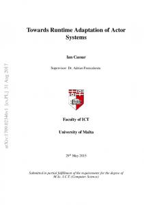
4.1 Application Example The experiments builds upon the Common Component Modeling Example (CoCoME) [HKW` 08]. CoCoME is a representative of a trading system as it can be found in a supermarket chain. It implements processes at a single cash desk as well as enterprisewide administrative tasks. CoCoME uses a database service hosted on data centers that may be distributed around the globe, as visualized in Figure 4.1. The figure illustrates the CoCoME core application and the global reach of prospective cloud providers (depicted as columns) that offer Database-as-a-Service (DBaaS). The supermarket chain is located within the European Union. Thus, sensitive data must not leave the EU, according to the privacy constraint introduced in Section 2.2. Advertisement of the supermarket chain leads to an increased amount of sales and thus to variations in the application’s usage profile (C1). Increased usage intensity may cause an upcoming performance bottleneck in the system. IT operators of the supermarket identify limited capacities of the data center currently hosting the database component as a cause of performance issues. To address the performance issue the database component may be migrated from one data center to another (C3). Migration may solve the performance issue but may violate the privacy constraint, stipulated in privacy policies, if the new data center is located outside the EU. The same applies to the replication (C4) of the database component that may result in better load balancing however may cause a privacy issue.
24
Figure 4.1: Deployment of CoCoME
4.2 Research Questions Efficiency is a key aspect of run-time models. In a systematic literature review, Szvetits and Zdun [SZ13] identified that performance (i.e. metrics on time) is by far (55%) the most often used quality aspect for evaluating approaches dealing with run-time models. Resource consumption (e.g., memory usage) is used at the second oftenest (10%). Therefore, we focus on reaction time and memory consumption while analyzing the scalability of iObserve. Furthermore, we analyze the advantage of applying iObserve in form of a cost-benefit ratio in comparison to analyzing original Kieker log-files. RQ1: How does iObserve scale? In iObserve, two transformation stages TP reprocess and TRun´time U pdate are used to continuously preprocess monitoring events and subsequently update the run-time model on that basis in certain intervals. Therefore, the two stages must be addressed separately. As simultaneous user interactions of multi-tenant cloud applications may lead to a massive amount of events, we put strong emphasis on examining the scalability of the usage model update in our evaluation. The run-time changes migration (C3) and replication (C4) occur relatively seldom, compared to user interactions with the application, and only require the adaptation of few attributes by the transformations. Thus, we focus on changes of the usage profile (C1) in the experiments because usage-related events are created continuously whenever the application faces a user interaction. Usage profile changes require processing a variety of monitoring events and, therefore, are well suited to examine scalability of iObserve in worst case. Technically speaking, TP reprocess must be able to cope with the number of monitoring events originating from the application. Therefore, it is important to be able to process more records in a given time unit than the monitoring can produce. Furthermore, the processing rate should not decrease over time to allow effective continuous processing. As the temporary result of TP reprocess are stored in memory, the memory consumption is important to determine the scalability of the preprocessing. The processing time of TP reprocess affects primarily the age of the data for the subsequent TRun´time U pdate transformation introducing an offset for the reaction time.
25
For the model updates performed by TRun´time U pdate it is important that their processing time is as short as possible so that the update interval can be more frequent, resulting in a smaller time where model and application are divergent. Furthermore, the memory consumption by the transformation and the updated models determine how many events can be processed limiting the size of the run-time model. The complete reaction time is determined by the monitoring overhead [HWH12, WFH14], the processing time of TP reprocess , the interval length and the processing time of TRun´time U pdate . Whereas monitoring and preprocessing together define an overall offset for the age of the data, and the interval and processing time of the runtime model update define the maximum time until a monitoring event is reflected in the model. RQ2: How is the cost-benefit ratio of iObserve? Benefit refers to the comprehensibility of the outcomes from the humans’ perspective by comparing a PCM instance to traditional monitoring outcomes. Cost refers to the effort (i.e. the number of steps) that must be performed by users to update the run-time model subsequent to a change identified at run-time.
4.3 Experiment Setting The experiment setting is based on the application example comprising one CoCoME instance utilizing a data service. The overall setup is tailored to evaluate performance and resource properties and allows to simulate migration and replication scenarios. However, in this evaluation, we focus on the scalability of the analysis in iObserve which is why these properties of the setup are not investigated in this paper. The ability to also evaluate migration events in the same setup allows us to re-use the setup for these purposes in future and relate present results to such future evaluations. In our experiments, we use a model and a conforming implementation of CoCoME [HKW` 08]. The implementation is realized with Java Enterprise Beans (EJB) and Java Servlets providing the external interface of the store application. The application is deployed on a PaaS system which we realized with Glassfish 4.01 . We choose an application server compliant to JEE as JEE is widely used in productive PaaS settings such as in OpenStack2 . As we assume in this scenario that the PaaS service is rented, we cannot instrument Glassfish or use its internal monitoring system. We therefore, can only use probes inserted in our EAR bundle containing CoCoME which we can deploy over a PaaS interface. The monitoring probes comprise of interceptors, filters, and life cycle listeners for for EJB and servlet calls. The system utilizes a database node which is realized with a PostgreSQL database which provides migration features necessary to migrate and replicate the database. Both nodes use an VirtualBox cloud image based on Ubuntu 14.04 which is executed on an OpenStack cloud infrastructure. As technological basis for monitoring, we selected the Kieker framework [HWH12], as it has been proven to be fast and reliable [HE14]. Recently, it has been augmented by a 1 https://glassfish.java.net/ 2 https://www.openshift.com
26
language and technology independent record notation [JHS13] which allows to extend the data model used for monitoring and supports different languages and technologies. Furthermore, Kieker is able to collect multiple measurements at once and store them in one record, reducing the number of lookups for data compared to single value stores, like the SMM [OMG12]. The evaluation is driven by varying workloads which are generated via the thread group function of Apache JMeter3 to simulate parallel users following a predefined behavior forming a workload profile. The workload profile resembles the usage intensity of the CoCoME system during a successful advertising campaign. Before the advertising campaign, CoCoME faces a certain usage profile that is characterized 10 users accessing the service over 10 iterations, followed by an product price change to simulate the preparations for an advertising campaign. Advertisements lead then to an increased amount of sales. Consequently, the system usage intensity increases, which is reflected by a greater number of users. In the context of our evaluation, we performed this scenario with different configurations of the workload driver which altered the number of concurrent users during the advertising campaign from one to 130 users to estimate the maximum utilization of the Glassfish service. We established that in our configuration a maximal utilization of the service is reached with 70 concurrent user threads. Higher number of threads resulted in sporadic timeouts of the Glassfish HTTP connection. Subsequently, we executed this 70 user workload profile with different user iterations starting at 10 iterations going up to 2000 iterations. This was necessary to be able to produce different amounts of entry call events for the TRun´time U pdate transformation. During the experiments, Kieker monitored calls to the application interface exposed through the servlet and EJB API and provides additional information on deployments and undeployments. These events are transmitted via TCP to an off-site analysis node4 described in the monitoring section Section 3.4 which can be used to trigger the necessary run-time model update transformations to realize deployment and usage model adaptations in the run-time model. As Kieker has been tested with respect to reliability, we conclude that our measurements are not distorted by any data source. In our experiment we logged all Kieker observations to be able to send monitoring events as fast as possible to the analysis to test its throughput and to be able to provide monitoring data for other researchers. While this implies an offline analysis our analysis can also use a TCP connector between monitoring and analysis which has been show to be the fastest transfer mechanism [WFH14]. The hardware setup of our experiment consists of different workload drivers connected to the software system via an simulated 100Mbit/s Ethernet link and three cloud instances running on our OpenStack cloud on separate CPUs with different resource setups. The Glassfish is running on a m1.medium instance with two virtual CPUs based on Intel Xeon E312xx 2 GHz, 4 GB RAM and 40 GB root disk. The databases hosted on a PostgreSQL server is running on one m1.small instance (2 GB RAM, 20 GB root disk) and one m1.medium instance. All cloud instances are interconnected by 3 http://jmeter.apache.org/ 4 https://sdqweb.ipd.kit.edu/wiki/iObserve
27
a virtual network realized in memory when stored on the same machine or via an 1 GBit/s Ethernet connection. Furthermore, a load balancer used as fail over switch between both databases is used to guarantee migration without interruption. The initial placement strategy of the cloud service is to place each cloud instance on a separate hardware host.
4.4 Experiment Results In the experiments, we observed the executed CoCoME application at run-time using Kieker. While observing the application, we vary its workload and, therefore, the number of monitoring event created by Kieker. The monitored events are input to the iObserve analysis which detects changes to component-structure, deployment, and usage profile. The analysis creates sequences of entry calls traversed in the observed sessions using the transformation TEntryCall . From the 53 214 743 monitoring events of our longest experiment the TP reprocess created 328 822 entry call events which where then processed by the subsequent transformations. Based on the sequences we update the control flow and workload within the PCM usage model using the transformation TEntryEventSequence which is part of the TRun´time U pdate transformation (cf. Figure 3.6). The inspection of the generated log files confirmed the effectiveness of the transformations in updating the usage model based on entry call events. Scalability: The Kieker monitoring framework imposes a small and constant overhead to the execution of each monitored operation [HWH12]. Therefore, the overhead grows linear with the number of operations [WH12]. To reduce the load on the monitored system, all monitoring events are transferred as a binary data stream via TCP to an off-site analysis node. As Kieker provides different transport mechanisms, the transfer could be realized with any number of technologies. However, the TCP stream is the most performant method so far [WFH14]. The analysis is realized with an pipe and filter framework. In iObserve, the transformations discussed in Section 3.8 are realized through such filters. Therefore, we refer to specific transformations within the mega model when analyzing reaction time and memory consumption. The FHeartbeat , FDeployment , and FF low transformations (see Figure 3.5) are realized by a RecordSwitch filter which has a constant execution time per event, as it splits the input stream on the basis of the record type. The TDeployment transformation, reconstruction deployment events out of heartbeat events, has a execution time which directly depends on the number of deployed components which use the heartbeat feature to report that they are deployed, as for each deployed component one registry entry must be maintained. The TEntryCall transformation selects out of the event stream three records per call trace and then reduces them to one EntryCallEvent. Therefore, the memory consumption and execution time of the transformation depends on the number of parallel call traces the deployed application can handle. In large installations with millions of parallel requests, the analysis can be parallelized [FSH14]. In CoCoME the maximum monitored
28
call trace length is 80 operations resulting in 161 monitoring events which are thereby reduced to one EntryCallEvent. Larger application may have even longer traces resulting in even higher reduction rates in this step of the analysis. The TEntryCallSequence transformation processes the events emitted by TEntryCall . In general, this transformation represents each interface operation which has been record by an EntryCallEvent in one vertex. Multiple EntryCallEvents of the same interface operation do not result in additional vertices. The sequence of EntryCallEvents result in edges between vertices. However, an edge is only added if no edge already exists between two vertices in the same direction. Otherwise only the edge count is increased. Therefore, the maximum number of objects necessary to represent a call sequence is v ` pv 2 ´ vq with v “ |V | representing all vertices and two edges between each pair of vertices. The result model comprising vertices and edges is transferred to the consecutive transformation TEntryEventSequence (part of TRun´time U pdate ) based on a configurable trigger based on a time interval and the number of processed entry calls, resulting in a low frequence of transformation executions. Therefore, the analysis can handle an extensive number of monitoring events, as the memory consumption and the potential processing time are bound to the size of model parts stored in memory which are only a couple of elements. In our experiment, the application server was not able to produce enough monitoring events to cause a measurable load on the analysis node while itself measured a load of 2.04. In addition, we evaluated the two parts of analysis separately which are represented by TP reprocess and TRun´time U pdate as depicted in Figure 3.1. As sub-transformations of TP reprocess are triggered for every incoming record and TRun´time U pdate only in certain intervals, we measured processing rate or time, and memory consumption separately. In the first evaluation, we examined the preprocessing part of iObserve, represented by TP reprocess , through increasing amounts of records to be processed. Figure 4.2a depicts the processing rate for various number of records. The figure shows that for low number of records the processing rate is low but it increases rapidly until a more stable processing rate is reached around 10 000 000 records converging to a processing rate of 900 records/ms even up to 53 214 743 input records. This effects is caused by buffers in the underlying pipe and filter framework, the operating system and the Java run-time optimizations. Especially, the latter requires several iterations until optimizations are applied. However, this implies that the processing rate is not negatively influenced by large amounts of processed records. Figure 4.2b depicts the memory consumption for increasing amount of created EntryCallEvents (up to 328 822 in the long running workload). After a warm-up phase, the memory consumption curve exhibits a small linear gradient, as it is expected by collecting entry call events for further processing. In conclusion, the preprocessing part of iObserve scales well in terms of processing rate and memory consumption. The second evaluation we focused on the TRun´time U pdate transformation, for increasing amounts of records to be processed. Figure 4.3a depicts the processing time of a usage model transformation for increasing amount of observed records. It is shown that after a linear growth with a high gradient until 3 000 processed records, the slope of the curve flattens but remains linear. The higher starting increase is due to Java
29
0
10000
20000
30000
40000
400 300 200
● ● ● ● ● ● ● ● ● ● ● ● ● ● ● ● ● ● ●
Memory Consumption (MB)
●
●
100
200 400 600 800 0
Processing Rate (records/ms)
● ● ●
●● ●● ●
50000
0
Processed records (k records)
50
100
150
200
250
300
Number of EntryCallEvents (k records)
(a) Processing rate
(b) Memory consumption
Figure 4.2: Scalability of record preprocessing represented by TP reprocess run-time optimizations and internal buffers of the underlying pipe and filter framework.
0
6
●
7
8 ●● ● ● ● ● ● ● ● ● ● ● ● ● ●
●●●
5
Memory (MB)
●
●
●● ● ● ● ● ● ● ● ● ● ● ●● ● ● ● ● ● ● ● ●
● ●
4
200 400 600 800 0
Processing time (ms)
●
● ●
10000
20000
30000
40000
50000
0
Processed records (k records)
10000
20000
30000
40000
50000
Processed records (k records)
(a) Processing time
(b) Memory consumption
Figure 4.3: Scalability of the usage model transformation of TRun´time
U pdate
The memory consumption of the model update transformation was measured for all different workload configurations and resulted in values between 3.8 MB up to 8.5 MB. However, the memory consumption did not increase with higher number of processed records or entry call events. While the measurements where taken from Java run-time functions after suggesting garbage collection to the Java run-time, other effects on memory consumption where still higher than the effect by the transformation itself. Based on user profile defined in the workload driver, the resulting model update should only differ in edge weights and not in the overall size of the model. Therefore, memory consumption after the transformation should not increase with higher amounts
30
of events. While Figure 4.3b does neither support nor falsify that assumption, it shows that memory consumption by the transformation and its results is very small. Therefore, not presenting a threat to the scalability. Cost-Benefit: For answering RQ2 (cost-benefit) we apply the following line of argumentation by comparing the iObserve results to observation results without using our approach. The first argument refers to the comprehensibility of the outcomes from the humans’ perspective by comparing a PCM instance to traditional monitoring log files. Current monitoring frameworks, such as Kieker, provide an unstructured and technology-specific collection of monitoring logs or, at best, a graphical aggregation of them in form of rudimentary models, e.g. component model or petri net. The PCM consists of several partial models, each tailored to specific roles such as component developer, system architect, or domain expert [BKR09]. Owing to modeling constructs specific to roles in a software development process, we consider the PCM instance as more comprehensibility for humans during evolution than a collection of monitoring logs or a rudimentary model. This perception is supported by results of empirical studies on the applicability of component-based models by Martens et al. [MKPR11]. Furthermore, the generated PCM instance can be applied for run-time analysis using existing solvers (cf. [BKR09, SMP14]) without any additional intervention. In consequence, we consider the iObserve outcomes (i.e. the PCM instance) more beneficial for long-term evolution than traditional monitoring outcome. The second argument refers to the number of steps that must be performed by users to update the run-time model subsequent to a change identified at run-time. Owing to the automation that comes along with iObserve, the users do not have to perform any step manually. The model is updated automatically. In contrast, without iObserve users have to search in log-files for required information. They have to interpret the log files, e.g. for identifying system calls, software components, and deployment information. Even in case of models provided by monitoring frameworks [HWH12], the models have to be compared or merged manually and extended by quality-relevant parameters to allow for quality analysis. To the best of our knowledge there is no monitoring tool that provides an output comparable to the PCM. In consequence, the application of iObserve exhibits less effort for updating run-time architecture models than applying traditional monitoring approaches. Since, compared to traditional monitoring approaches, the outcome of iObserve is more beneficial and simultaneously the application of iObserve is less costly for users, iObserve exhibits a better cost-benefit ratio.
31
5 Related Work In this section, we, firstly, discuss work that reuse design-time models during run-time. Secondly, we discuss work on model extraction that creates models based on monitoring data. We point out how existing run-time model approach fall short in reflecting the changes C1-4 introduced in Section 2.2. Work on reusing design-time models during run-time such as [MBJ` 09, ICH11, SM11, CDPEV08] employs design-time models as foundation for reflecting software systems during run-time. The work in [MBJ` 09] reuses sequence diagrams created during run-time in order to verify running applications against their specifications. Every deviation between the observed and the specified event sequences are interpreted as implementation faults. The proposed sequence diagrams exhibit a good understandability from a developer perspective. However, the approach does not include any updating mechanisms that changes the model whenever the reflected systems is being alternated. Consequently, none of the introduced usage or platform changes (C1–C4 ) are supported. Other than this, the run-time models in [ICH11, SM11, CDPEV08] are modified during run-time. These approaches employ workflow specifications created during design-time in order to carry out performance and reliability analyses during run-time. The approaches update the workflow models with respect to quality information of the services bound to the workflow. For instance, the work in [SM11] updates services response times, whenever an executed service responds. However, these approaches reflect control flows by means of workflow specifications and do not cover architectural designs, which is useful when evolving the application. Further, this work updates the model with respect to single parameters and does not change the models structure, which is required to reflect the replication and migration of components (C3 and C4 ). Work on model extraction update model structures during run-time. Approaches such as [SHC` 11, SAG` 06, vdASS11, vH14, BHK11a, vMvHH11] establish the causal relation between executed applications and run-time models based on monitoring events (for a comprehensive list of approaches see [SZ13]). Starting with ”blank” models, these approaches create models during run-time from scratch by, e.g., observing and interpreting operation traces. Consequentially, they disregard information that cannot be gathered from monitoring data, such as design perspectives on component structures and component boundaries. For instance, the work in [vdASS11] exploits process mining techniques for extracting state machine models from event logs. Without knowledge about the component structure developed during designtime, the extracted states cannot be mapped to the initial application architecture. In consequence, the model hierarchy is flat and unstructured, which hinders software developers and maintainers in understanding the current situation of the application at hand. Furthermore, the work reflects processes but neither components nor their
32
relations (C3 and C4 ). Other than this, the approach in [SAG` 06] extracts components and their relations from events for the sake of comparing actual and intended architectures. To this end, the work modifies the run-time model by model transformation rules in response to single events. With this approach we share the application of transformation rules to update a model based on monitoring events. The resulting model in [SAG` 06] is coarse-grained, which is sufficient for deciding whether an actual composition maps to the intended composition. However, when conducting performance and privacy analyses the observation and reflection of resource consumptions is crucial. Reflecting the consumption by the means of usage profiles requires to process event sets rather than single events, which outruns the event processing capacity of this approach (C1 and C2 ). Furthermore, the observation and analysis of usage and component changes causes complex relationships between probing applications, probe types, and mapping these types to run-time models, which is not discussed in this contribution. To summarize, design-time models that are reused during run-time provide a good readability, but are not updated with respect to structural changes yet. However, structural updates are required to reflect cloud migration (C3 ) and replication (C4 ). Work on model extraction automatically creates run-time models from scratch, which is useful for performance analysis. However, as design-time decisions on application architectures cannot be derived from monitoring events the resulting models lack understandability.
33
6 Conclusion We addressed, in this paper, run-time architecture model updates and run-time analysis for changes in cloud-based systems by considering run-time adaptation and evolution as two mutual, interwoven activities that influence each other. The proposed iObserve approach allows automated adaptation at run-time and simultaneously supports software evolution through run-time observation and continuous quality analysis. iObserve provides several contributions. It enables the specification of the correspondence between low-level monitoring data on one side and component-based architecture models and the usage of these models on the other side both for automated adaptation and for evolution. iObserve comes along with mechanisms for promoting run-time observation data to design models, thereby continuously updating and calibrating those design models during run-time while keeping the models semantically rich and comprehensible by humans. We integrate our iObserve approach into a model-driven engineering process and systematically describe the required activities by means of a life cycle. Part of this process is the model-driven instrumentation, which supplies our run-time monitoring approach with observation data. We argued for the effectiveness of iObserve in maintaining the model abstraction level during continuous model update based on observed run-time changes. We evaluated iObserve with lab experiments deploying the CoCoME benchmark on an OpenStack cloud. The experiments showed that (a) the analysis part of iObserve scales linearly in terms of processing rate and memory consumption, and (b) the memory consumption of the transformation scales linearly for large amount of records. Furthermore, we argued for the cost/benefit ration of iObserve compared to analysis on traditional monitoring outcomes. Future work includes automated code generation from the updated architecture models to cover the entire MAPE loop. Initial work has been performed on a data model language supporting entity models based on the Java persistence API, and a language to formulate business functions representing the implementation of interface methods of component types in the PCM. Both languages are available in the CoCoME SVN repository1 . Furthermore, we will provide documentation, code, and experiment data to allow others to use and examine our setup. We intend to examine the applicability and usefulness of iObserve from the practitioners’ perspective in industry by conducting case studies in collaboration with industry partners. For the evolution phase of iObserve we plan to provide guidelines to engineers for long-term evolution of software systems.
1 https://svnserver.informatik.kit.edu/i43/svn/code/CoCoME-SPP/trunk/src/tool
34
Bibliography [AFG` 10] Michael Armbrust, Armando Fox, Rean Griffith, Anthony D. Joseph, Randy Katz, Andy Konwinski, Gunho Lee, David Patterson, Ariel Rabkin, and Ion Stoica. A view of cloud computing. Communications of the ACM, 53(4):50–58, 2010. [B` 12] Anton Beloglazov et al. Energy-aware resource allocation heuristics for efficient management of data centers for cloud computing. Future Generation Computer Systems, 28(5):755–768, 2012. [Bau93] Falko Bause. Queueing petri nets - a formalism for the combined qualitative and quantitative analysis of systems. In In Proceedings of the 5th International Workshop on Petri nets and Performance Models. IEEE, pages 14–23. IEEE Computer Society, 1993. [BCD` 12] Antonio Bucchiarone, Cinzia Cappiello, Elisabetta Di Nitto, Sergei Gorlatch, Dominique Mail¨ander, and Andreas Metzger. Design for selfadaptation in service-oriented systems in the cloud. In Dana Petcu and Jose Luis V´ asquez-Poletti, editors, European Research Activities in Cloud Computing. Cambridge Scholars Publishing, 2012. [BHK11a] F. Brosig, N. Huber, and S. Kounev. Automated extraction of architecture-level performance models of distributed component-based systems. In 2011 26th IEEE/ACM International Conference on Automated Software Engineering (ASE), pages 183–192, 2011. [BHK11b] Fabian Brosig, Nikolaus Huber, and Samuel Kounev. Automated extraction of architecture-level performance models of distributed componentbased systems. In Perry Alexander, Corina S. Pasareanu, and John G. Hosking, editors, ASE, pages 183–192. IEEE, 2011. [BHK12] Fabian Brosig, Nikolaus Huber, and Samuel Kounev. Modeling parameter and context dependencies in online architecture-level performance models. In Proceedings of the 15th ACM SIGSOFT Symposium on Component Based Software Engineering, CBSE ’12, pages 3–12, New York, NY, USA, 2012. ACM. [BKR09] Steffen Becker, Heiko Koziolek, and Ralf Reussner. The Palladio component model for model-driven performance prediction. J. of Systems and Software, 82:3–22, 2009.
35
[CDPEV08] Gerardo Canfora, Massimiliano Di Penta, Raffaele Esposito, and Maria Luisa Villani. A framework for QoS-aware binding and re-binding of composite web services. Journal of Systems and Software, 81(10):1754– 1769, 2008. [Cla10] R. Clarke. User requirements for cloud computing architecture. In 10th IEEE/ACM International Conference on Cluster, Cloud and Grid Computing (CCGrid), pages 625–630, 2010. [CTB12] Benoit Combemale, Xavier Thirioux, and Benoit Baudry. Formally defining and iterating infinite models. In RobertB. France, J¨ urgen Kazmeier, Ruth Breu, and Colin Atkinson, editors, Model Driven Engineering Languages and Systems, volume 7590 of Lecture Notes in Computer Science, pages 119–133. Springer Berlin Heidelberg, 2012. [CWM` 14] Clarissa Cassales Marquezan, Florian Wessling, Andreas Metzger, Klaus Pohl, Chris Woods, and Karl Wallbom. Towards exploiting the full adaptation potential of cloud applications. In ICSE 2014 6th Int’l Workshop on Principles of Engineering Service-Oriented and Cloud Systems (PESOS), May 31, 2014, Hyderabad, India. ACM, 2014. [dLGM` 13] Rog´erio de Lemos, Holger Giese, Hausi A M¨ uller, Mary Shaw, Jesper Andersson, Marin Litoiu, Bradley Schmerl, Gabriel Tamura, Norha M Villegas, Thomas Vogel, et al. Software engineering for self-adaptive systems: A second research roadmap. In Software Engineering for Self-Adaptive Systems II, volume 7475 of Lecture Notes in Computer Science, pages 1–32. Springer Berlin Heidelberg, 2013. [EAB02] Tzilla Elrad, Omar Aldawud, and Atef Bader. Aspect-oriented modeling: Bridging the gap between implementation and design. In Don Batory, Charles Consel, and Walid Taha, editors, Generative Programming and Component Engineering, volume 2487 of Lecture Notes in Computer Science, pages 189–201. Springer Berlin Heidelberg, 2002. [EEPT06] Hartmut Ehrig, Karsten Ehrig, Ulrike Prange, and Gabriele Taentzer. Fundamentals of Algebraic Graph Transformation. Monographs in Theoretical Computer Science. An EATCS Series. Springer, 2006. [Fav04] Jean-Marie Favre. Foundations of model (driven) (reverse) engineering – episode i: Story of the fidus papyrus and the solarus. In POST-PROCEEDINGS OF DAGSTHUL SEMINAR ON MODEL DRIVEN REVERSE ENGINEERING, 2004. [FH11] S¨ oren Frey and Wilhelm Hasselbring. The CloudMIG approach: Modelbased migration of software systems to cloud-optimized applications. JAS, 4(3 and 4):342–353, 2011.
36
[FSH14] Florian Fittkau, Phil Stelzer, and Wilhelm Hasselbring. Live visualization of large software landscapes for ensuring architecture conformance. In ECSAW 2nd International Workshop on Software Engineering for Systems-of-Systems 2014 (SESoS 2014). ACM, August 2014. [GRG` 14] Ursula Goltz, Ralf Reussner, Michael Goedicke, Wilhelm Hasselbring, Lukas M¨ artin, and Birgit Vogel-Heuser. Design for future: managed software evolution. Computer Science – Research and Development, 2014. [HE14] Klaus Schmid Holger Eichelberger. Flexible resource monitoring of java programs. Journal of Systems and Software, 2014. [Hei14] Robert Heinrich. Aligning Business Processes and Information Systems New Approaches to Continuous Quality Engineering. Springer, 2014. [HHJ` 13] Wilhelm Hasselbring, Robert Heinrich, Reiner Jung, Andreas Metzger, Klaus Pohl, Ralf Reussner, and Eric Schmieders. iObserve: Integrated Observation and Modeling Techniques to Support Adaptation and Evolution of Software Systems, 2013. [HKW` 08] Sebastian Herold, Holger Klus, Yannick Welsch, Constanze Deiters, Andreas Rausch, Ralf Reussner, Klaus Krogmann, Heiko Koziolek, Raffaela Mirandola, Benjamin Hummel, et al. Cocome-the common component modeling example. In The Common Component Modeling Example, pages 16–53. Springer, 2008. [HSJ` 14] Robert Heinrich, Eric Schmieders, Reiner Jung, Kiana Rostami, Andreas Metzger, Willhelm Hasselbring, Ralf Reussner, and Klaus Pohl. Integrating run-time observations and design component models for cloud system analysis. In 9th International Workshop on Models at run.time, 2014. [HWH12] Andr´e van Hoorn, Jan Waller, and Wilhelm Hasselbring. Kieker: A framework for application performance monitoring and dynamic software analysis. In Proceedings of the 3rd ACM/SPEC International Conference on Performance Engineering (ICPE 2012), pages 247–248. ACM, 2012. [ICH11] Dragan Ivanovic, Manuel Carro, and Manuel Hermenegildo. Constraintbased runtime prediction of sla violations in service orchestrations. In Service-Oriented Computing, pages 62–76. Springer, 2011. [ISO05] ISO/IEC. 19502, information technology – meta object facility, 2005. [JHS13] Reiner Jung, Robert Heinrich, and Eric Schmieders. Model-driven instrumentation with Kieker and Palladio to forecast dynamic applications. In KPDAYS, pages 99–108, 2013. [JHS` 14] Reiner Jung, Robert Heinrich, Eric Schmieders, Misha Strittmatter, and Wilhelm Hasselbring. A method for aspect-oriented meta-model evolution. In Proceedings of the 2Nd Workshop on View-Based,
37
Aspect-Oriented and Orthographic Software Modelling, VAO ’14, pages 19:19–19:22, New York, NY, USA, July 2014. ACM. [Jun13] Reiner Jung. Data type language, 2013. [Jun14] Reiner Jung. Geco: Automatic generator-composition for aspect-oriented dsls. In Proceedings of the MODELS 2014 Doctoral Symposium, November 2014. [Kou06] Samuel Kounev. Performance modeling and evaluation of distributed component-based systems using queueing petri nets. IEEE Transactions on Software Engineering, 32(7):486–502, 2006. [Koz10] Heiko Koziolek. Performance evaluation of component-based software systems: A survey. Perform. Eval., 67(8):634–658, 2010. [LZ11] Sebastian Lehrig and Thomas Zolynski. Performance prototyping with protocom in a virtualised environment: A case study. Proceedings to Palladio Days, pages 17–18, 2011. [MBJ` 09] Brice Morin, Olivier Barais, Jean-Marc Jezequel, Franck Fleurey, and Arnor Solberg.
[email protected] to support dynamic adaptation. Computer, 42(10):44–51, 2009. [MD12] Andreas Metzger and Elisabetta Di Nitto. Addressing highly dynamic changes in service-oriented systems: Towards agile evolution and adaptation. In Xiaofeng Wang, Nour Ali, Isidro Ramos, and Richard Vidgen, editors, Agile and Lean Service-Oriented Development: Foundations, Theory and Practice. IGI Global, 2012. [MKPR11] Anne Martens, Heiko Koziolek, Lutz Prechelt, and Ralf Reussner. From monolithic to component-based performance evaluation of software architectures. Empirical Software Engineering, 16(5):587–622, 2011. [MNS01] G.C. Murphy, D. Notkin, and K.J. Sullivan. Software reflexion models: bridging the gap between design and implementation. IEEE Transactions on Software Engineering, 27(4):364–380, 2001. [MPS99] K. McCloghrie, D. Perkins, and J. Schoenwaelder. Structure of Management Information Version 2 (SMIv2). RFC 2578 (Standard), April 1999. [OMG11] OMG. OMG Unified Modeling Language (OMG UML), Superstructure, Version 2.4.1, August 2011. [OMG12] OMG. Structured Metrics Meta-Model (SMM) 1.0, 2012.
38
[PPPM10] M. Papazoglou, K. Pohl, M. Parkin, and A. Metzger, editors. Service Research Challenges and Solutions for the Future Internet: S-Cube – Towards Mechanisms and Methods for Engineering, Managing, and Adapting Service-Based Systems, volume 6500 of Lecture Notes in Computer Science. Springer, Heidelberg, Germany, 2010. [RGH` 06] Matthias Rohr, Simon Giesecke, Wilhelm Hasselbring, Marcel Hiel, Willem-Jan van den Heuvel, and Hans Weigand. A classification scheme for self-adaptation research. In Proceedings of the International Conference on Self-Organization and Autonomous Systems In Computing and Communications (SOAS’2006), page 5, September 2006. [RRMP08] Andreas Rausch, Ralf Reussner, Raffaela Mirandola, and Frantisek Plasil, editors. The Common Component Modeling Example: Comparing Software Component Model, volume 5153 of Lecture Notes in Computer Science. Springer, 2008. [RS95] J. A. Rolia and K. C. Sevcik. The method of layers. IEEE Trans. Softw. Eng., 21(8):689–700, 1995. [SAG` 06] B. Schmerl, J. Aldrich, D. Garlan, R. Kazman, and H. Yan. Discovering architectures from running systems. IEEE Transactions on Software Engineering, 32(7):454–466, July 2006. [SBPM09] David Steinberg, Frank Budinsky, Marcelo Paternostro, and Ed Merks. EMF: Eclipse Modeling Framework 2.0. Addison-Wesley Professional, 2nd edition, 2009. [SHC` 11] Hui Song, Gang Huang, Franck Chauvel, Yingfei Xiong, Zhenjiang Hu, Yanchun Sun, and Hong Mei. Supporting runtime software architecture: A bidirectional-transformation-based approach. Journal of Systems and Software, 84(5):711–723, May 2011. [SM11] Eric Schmieders and Andreas Metzger. Preventing performance violations of service compositions using assumption-based run-time verification. In Towards a Service-Based Internet, pages 194–205. Springer, 2011. [Smi90] Connie U. Smith. Performance Engineering of Software Systems. AddisonWesley Longman Publishing Co., Inc., Boston, MA, USA, 1st edition, 1990. [SMP14] Eric Schmieders, Andreas Metzger, and Klaus Pohl. A runtime model approach for data geo-location checks of cloud services. In Service-Oriented Computing - 12th International Conference, ICSOC 2014, Paris, France, November 3-6, 2014. Proceedings, pages 306–320, 2014. [SZ13] Michael Szvetits and Uwe Zdun. Systematic literature review of the objectives, techniques, kinds, and architectures of models at runtime. SoSyM, December 2013.
39
[vdASS11] W.M.P. van der Aalst, M.H. Schonenberg, and M. Song. Time prediction based on process mining. Information Systems, 36(2):450–475, April 2011. [VG10] Thomas Vogel and Holger Giese. Adaptation and abstract runtime models. In Proceedings of the 2010 ICSE Workshop on Software Engineering for Adaptive and Self-Managing Systems, SEAMS ’10, pages 39–48. ACM, 2010. [VG14] Thomas Vogel and Holger Giese. On unifying development models and runtime models (position paper). In 9th International Workshop on Models at run.time. CEUR, 2014. [vH14] Andr´e van Hoorn. Model-Driven Online Capacity Management for Component-Based Software Systems. Number 2014/6 in Kiel Computer Science Series. Department of Computer Science, Kiel University, Kiel, Germany, 2014. Dissertation, Faculty of Engineering, Kiel University. [vHRH08] Andr´e van Hoorn, Matthias Rohr, and Wilhelm Hasselbring. Generating probabilistic and intensity-varying workload for web-based software systems. In Proc. SPEC International Performance Evaluation Workshop 2008, LNCS, pages 124–143, Heidelberg, 2008. Springer. [vMvHH11] Robert von Massow, Andr´e van Hoorn, and Wilhelm Hasselbring. Performance simulation of runtime reconfigurable component-based software architectures. In Ivica Crnkovic, Volker Gruhn, and Matthias Book, editors, ECSA, volume 6903 of Lecture Notes in Computer Science, pages 43–58. Springer, 2011. [WFH14] Jan Waller, Florian Fittkau, and Wilhelm Hasselbring. Application performance monitoring: Trade-off between overhead reduction and maintainability. In Proceedings of the Symposium on Software Performance 2014, pages 1–24. University of Stuttgart, November 2014. [WH12] Jan Waller and Wilhelm Hasselbring. A comparison of the influence of different multi-core processors on the runtime overhead for applicationlevel monitoring. In Victor Pankratius and Michael Philippsen, editors, Multicore Software Engineering, Performance, and Tools, volume 7303 of Lecture Notes in Computer Science, pages 42–53. Springer Berlin Heidelberg, 2012.
40