Email: {ianku|jtweng|giordano|gpau|gerla}@cs.ucla.edu. â DEIS, WiLab ...... Charles Graff, âA comparative study of AODV and OLSR on the ORBIT testbedâ ...
Running Consistent, Parallel Experiments in Vehicular Environment Ian Ku∗ , Jui-Ting Weng∗ , Eugenio Giordano∗† , Giovanni Pau∗ and Mario Gerla∗ ∗ Department
of Computer Science, University of California Los Angeles Email: {ianku|jtweng|giordano|gpau|gerla}@cs.ucla.edu † DEIS, WiLab, Universit`a di Bologna
Abstract—The comparison of different applications and protocols in vehicular ad hoc networks (VANETs) is a very difficult task. This is mainly due to the nature of VANET, for which it is virtually impossible to replicate the same exact environment in two separate experiments. This paper introduces a flexible experiment structure that will allow different protocols to be compared in the same mobility pattern and channel conditions in VANET. A virtualized environment is setup on each node where the combination of Xen and Gentoo software is used to create multiple virtual guests. All virtual guests on the same machine use different protocols and share the wireless interface. We compare the widely recognized ad-hoc routing protocols AODV and OLSR to demonstrate the novelty of our system. Experiment results show that even with arbitrary external interference and mobility pattern, meaningful comparisons between different protocols can be carried out. Index Terms—VANET, Testbed, OLSR, AODV.
I. I NTRODUCTION Technology of mobile ad hoc networks (MANET) has been studied for years [1]. The main advantages of MANET include easy deployment, distributed control, bandwidth efficiency and no need for infrastructure. Inspired by MANET, VANET is an emergent technology designed to improve safety, comfort, and convenience for vehicle drivers and passengers. The use of networking vehicles has attracted considerable attention from both research community and automotive industry and has spawned initiatives such as Inter-Vehicle Communication Systems (IVC) [2], Intelligent Transportation Systems [3]– [5]etc. VANETs enable Vehicle to Vehicle (V2V) and Vehicle to Infrastructure (V2I) communications. These new communication schemes open a new wide set of possible applications together with very challenging novel research topics. Due to various applications in VANET requiring multihop support, researchers have come up with several routing protocols for data dissemination. [18]–[21]. These results show the importance of routing to VANET. However, individuating the most appropriate protocol requires extensive comparison studies. Unfortunately, comparing VANET protocols is anything but trivial, as discussed below. Before the introduction of testbeds, VANET applications and protocols were evaluated via simulation. Through simulation tools such as ns-2, opnet, or qualnet, researchers were able to obtain results where the performance of various applications and protocols can be gauged. However, even the best of simulation tools cannot simulate the exact physical conditions
of the real world, and thus results can be unsatisfactory when compared with real world experiments. There are three main modeling challenges that VANET researchers face : traffic (mobility) pattern; radio propagation models, and environmental network interference. As the mobility pattern plays a very important role in VANET, it would be unrealistic to assume that mobile nodes are moving according to simple mobility schemes such as random walk, or random direction. A common approach is to separate the synthesis of mobility from the network simulation: first generate the entire node mobility trace through either road traffic simulators, public transportation schedule, or real time logs, and then feed the obtained trace as input to the network simulator. For example, in [6], the traffic log is first generated by a scalable traffic simulator (MMTS). However, the problem of this approach is that the radio propagation model in VANET cannot be simply extracted from city map and motion trace. The general approach to model radio propagation is to use well-established statistic models. Since buildings and other vehicles also interfere with the radio signal, real channel conditions are much more complicated. In [22], the authors provide a new signal propagation model to estimate signal coverage through existing maps. However, attenuation caused by dynamic factors such as trucks or obstacles, is still hard to reproduce. Unlike mobility models, it is very costly to record the channel conditions between every node pair and use them in simulation. Vehicular testbeds have been used to measure real channel conditions [23]. However, when running vehicular experiments, the mobility pattern changes from experiment to experiment, leading to inconsistent results. Similarly, external interference may be generated by surrounding wireless networks. This varies randomly in an urban environment and it is extremely difficult to measure and reproduce in a simulator. From the above we conclude that simulation results are unlikely to provide an accurate comparison of vehicular protocols because of the difficulty of modeling motion, propagation and interference in a realistic manner. The only safe method then, seems to be testbed measurements. Unfortunately, here another equally difficult challenge awaits us: experiment reproducibility. Suppose we run first routing algorithm A (say, AODV). Then, 10 minutes later, we run algorithm B (say OLSR). Can the results be fairly compared? Generally not, because in 10 minutes the external interference may have changed, the motion pattern of the various vehicles involved
in the experiments may have changed (for example, due to unpredictable traffic lights), and the radio propagation may have changed (say, due to mobile obstacle beyond our control). Thus, realism is definitely the big advantage of testbeds (with respect to simulation platforms). But now the problem of inconsistency of environmental conditions emerges. This is the challenge we address in this paper. Namely, we propose to implement a VANET testbed that is set up to compare different protocols in the exact same topology and channel conditions. The testbed contains multiple mobile nodes, and each node runs multiple virtual machines in parallel. We run a different protocol in each machine. We show that in this way a realistic, fair side-by-side comparison of the different protocols can be made. The rest of the paper is organized as follows: In section II, related work is introduced. Section III describes our system platform. The virtualization overhead is evaluated in section IV. Two protocols, AODV and OLSR are used to evaluate our platform, and the results are reported in section V. Conclusions and future extensions are presented in section VI. II. R ELATED W ORK The Wireless Signal Propagation Emulator developed at CMU [27] accurately emulates wireless signal propagation in a physical space. In fact it can be trained to replicate a number of different representative environments, including urban vehicular scenarios. The emulator takes in the signals generated by wireless network cards through the antenna port, subjects the signals to the same effects that occur in a real physical space (e.g. attenuation, multi-path fading, ...), and feeds the combined signals back into the wireless cards. The wireless emulator forms the basis for a wireless testbed that supports highly realistic experiments, while also being fully repeatable and easy to control. The emulator, however, has some limitations in reproducing arbitrary motion patterns. In addition, although the propagation scenario is very realistic, it is still artificially created, as opposed to measured in real life. Orbit [7] is a testbed that combines an indoor radio grid emulator and an outdoor field trial network. This testbed is available for use either via remote or on site access. The indoor radio emulator consists of 400 802.11 radio nodes in a 20x20 grid with a wired control channel to each node, and the outdoor field trial network consists of 50 nodes. Each wireless node is equipped with two 802.11 wireless interfaces. As to mobility support, the outdoor testbed is grounded, and the indoor emulator only supports virtual grid mobility. For example, in [8] the authors present a comparison between AODV and OLSR, performed through the ORBIT indoor testbed. The paper uses MAC level filtering to block the connection between two neighbor nodes, and create node connectivity that is similar to mobile nodes. The work provides some initial observations and indicates that AODV performs better than OLSR in terms of stability. The department of computer science at University Uppsala has opened to the community the Ad hoc Protocol Evaluation Testbed (APE Testbed) [9]. APE is an encapsulated execution
environment with tools for post test-run data analysis. It is like a small Linux package with ad hoc configuration and network traffic analysis tools. The package can be installed in either Windows or Linux environment to perform ad hoc experiments and display the result with GUI. In [10], Lundgred et al. used APE to evaluate the performance of AODV and OLSR with up to 37 nodes along indoor hallways and athletic fields. Their results show AODV performs better than OLSR when mobility is high. However, to the best of our knowledge, there has not any mobile or VANET experiment using APE testbed. Several vehicular experiments and testbeds have been proposed in the past [11]–[16]. However, none of them compared the behavior between different protocols. A general problem is that controlled mobility in vehicle experiments is almost impossible unless the scenario is extremely simple. Many academia facilities have mesh network testbeds that use AODV or OLSR to perform layer 3 routing. Some of the mesh testbeds are deployed in real environment, such as MIT RoofNet, Berlin Roof Net, and Mesh Networking from Microsoft Research [24]–[26]. These systems provide experimental results in real world channel condition, but lack node mobility. Various simulation studies compared the difference between AODV and OLSR, before any comparison could be performed on real world testbed. Among these researches, [17] is a simluation study that based on VANET scenario. In this paper, the authors compare AODV with OLSR through the Vehicular Mobility Model (VMM) they proposed. VMM considers both road and obstacles (macromobility) and the point of view of the driver (micromobility). To sum up, simulation can capture the node mobility well, but fails to provide realistic channel conditions (propagation and interference). On the other hand, the testbed approach provides a convincing channel condition, but cannot support complicated mobility at the same time. In this paper, a novel approach is used to perform parallel experiments. Thus, the mobility and channel condition do not need to be reproduced in order to compare different routing protocols.
III. OVERVIEW OF E XPERIMENT P LATFORM In this section we describe our experiment platform. The main purpose of this study is to provide the community with an experimental platform that allows the evaluation of different protocols and applications under the same environmental conditions. We propose to run several experiments together in one single run. Even if mobility pattern and channel conditions cannot be reproduced, experiments running at the same time still experience the same environment condition. The idea is to have multiple virtual machines running on the same mobile node, and each of them runs its own protocol and application, while sharing the same wireless card to communicate with the rest of the network. In the following we first describe the hardware platform and subsequently the software setup.
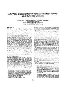
Fig. 1.
Node setup on a vehichle
A. Hardware Platform Our network nodes are common commercial laptops with an Intel Core 2 Duo CPU, 2GB of RAM and 120GB hard drive. Each laptop is instrumented with a Ubiquiti SRC wireless card with Atheros 802.11 wifi chipsets (AR5004). The Atheros 802.11 wifi chipset is supported by the open source Linux madwifi driver [32], that allows many customized settings including fixed channel selection, transmission power, and monitor mode. For our experiments all the wireless cards are in ad hoc mode, using channel 1 only. The transmission power is set to the hardware supported maximum (19dbm). The wireless card is connected to a magnetic mount antenna with 8dB nominal gain. Each laptop is also equipped with a GPS receiver to be able to track the position of the nodes during the experiments. Figure 1 shows an example of a node setup on a vehicle. B. Software Platform
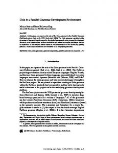
Fig. 2.
Software Platform
Each node is installed with the Linux Gentoo distribution (kernel version 2.6.21) patched with Xen. Xen is an open source industry standard virtualization environment that allows several virtual machines (Xen guests) to share the same hardware (see Figure 2). Each virtual machine can run a different operating system with different protocols and applications. In addition, the Xen platform provides the ability to connect the guest operating system to the host operating system (Xen host) through a virtual Ethernet bridge. This bridge internally connects to one virtual network card for each Xen guest, and handles all incoming and outgoing wireless traffic. Therefore,
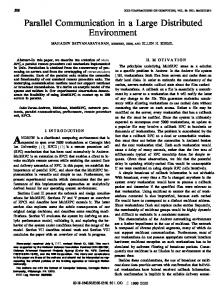
every Xen guest shares the same physical wireless card to communicate with the outside world. In addition to the first bridge, we setup a second bridge that allows communication between host and guest without interfering with experimental traffic. In order to perform better time synchronization, we use the second bridge to run network time protocol (NTP) and correct the time drift between Xen host and guests clocks. We also use of the second bridge to pass geo information to Xen guests. The Xen host is connected to the GPS device by gpsd [36]. Gpsd is an open source daemon that connects to the GPS device and provides a network socket interface for retrieval of the location information. Through the Ethernet bridge, Xen guests can access GPS information through the gpsd daemon. This allows the use of application and protocols that require GPS information to be used in our experiment system. The most important components on Xen guests are the routing module, the synchronization tool, and the network traffic generator application. Since each Xen guest is an independent system, it can run its own operating system and routing module. IV. X EN OVERHEAD E VALUATION Our virtualized approach requires the sharing of resources and introduces additional overhead over a regular Linux system. The overhead introduced by the system can be categorized into two ways: • Virtualization Overhead: the virtualization platform adds an extra software processing layer between applications and hardware. In addition, hardware resources are used to run the virtual machines. Therefore, the delay between the generation of a packet at application layer and the time it is sent out of the hardware interface is longer than for a regular Linux system with no virtualization. • Sharing Overhead: When multiple virtual machines transmit at the same time, they contend for the same physical medium. This contention causes lowers the maximum throughput the hardware can achieve and introduces extra delay due to the enqueueing of packets. In this section we investigate on the impact of such overhead factors and find the limitation introduced by our virtualization system. A. Virtualization Overhead In order to evaluate the overhead introduced by the virtualization platform we performed a set of experiments to compare the performance of a native Linux system and our virtualized environment. For the virtualized environment, we setup two Xen guests on the same machine. We then activate a constant UDP data flow that generates packets every 150ms destined to another wireless receiver, only from one of the Xen guests, while the other Xen guest remains idle. Figure 3 shows the end-to-end delay for both the native Linux system and the virtualized platform for an increasing packet size. A first observation is that the data transfer on the virtual environment suffers from higher latency. Moreover, an increase of the
Delay [ms]
22 20 18 16 14 12 10 8 6 4 2 0
Native Xen VM
0
600
Native Xen VM
500 Delay [ms]
packets size causes an increase of the delay for both systems. However, the virtualized environment suffers a higher increase. This can be explained by the fact that every packet generated by Xen guest needs to be copied in memory more times than in the native system before it reaches the outgoing interface. Nevertheless, the delay increase for the virtual environment is in the range of tens of milliseconds. Compared to the delay introduced by external factors such as multi-hop paths and channel contention, the overhead is negligible. In our field tests, our UDP traffic generator sends out 50 bytes per 150 ms. With this network load the overhead of the two systems is comparable.
400 300 200 100 0 0
100
200 300 Packet size [bytes]
400
500
Fig. 4. Overhead introduced by the Xen virtualization: packet transmission delay as a function of packet size for two UDP flows generated on two virtual machines and on a native Linux system
V. F IELD E XPERIMENTS
100
200
300
400
500
Packet size [bytes]
Fig. 3. Overhead introduced by the Xen virtualization: packet transmission delay as a function of the packet size for the native system and for the virtualized environment
B. Sharing Overhead On our virtualized platform, the Xen guests share the same physical resources. It is then important to understand what is the maximum network load at which the sharing of the same resource causes losses or excessive delays. The Xen host connects the Xen guests to the physical network interface through a Linux network bridge. The operative system provides a fair share of CPU time to the virtual machines, and thus to the read and write locks on the network bridge. The bridge queue policy is First In First Out (FIFO) that coupled with the fair share of the locks avoids starvation and provides fair sharing of the resources. In this section we plan to assess what is the ”safe zone” to run our experiments so that the sharing overhead does not affect the validity of our results. We setup one UDP traffic generator on two Xen guests destined to another wireless node. One Xen guest is running AODV and the other is running OLSR as routing. In order to force the maximum sharing overhead, both Xen guests generate data traffic at the same time. This is possible as the guests are synchronized through NTP. We compare the packet loss and the end-to-end delay experienced by our system to the one of a similar setup on a native Linux system. Figure 4 shows the average end-to-end delay for increasing packet sizes. We can observe that the delay remains negligible up to packet sizes of 400 bytes for the virtualized environment, for larger packet sizes the delay increases considerably. We can conclude that for the data load used in our experiments (50 bytes every 150 ms) the overhead introduced by the virtualization system is negligible.
We performed a set of eight rounds of experiments. In these eight rounds we varied the use of AODV and OLSR (singularly or in parallel), the use of the interference nodes and the number of mobile nodes. Table III reports the setup we used in each experiment. In this session we initially present the details of the setup for each experiment round. We then show that running subsequent experiments leads to different environmental conditions and therefore to incomparable performance results. Finally, we show that, using our platform, the two routing protocols experience the same environmental conditions over time and therefore their performance can be compared without any ambiguity. A. Experimental Setup Several software components were run on the Xen host and guest machines throughout all of our experiments. 1) Host Setup: Mactrace: Each Xen host runs a mactrace tool that periodically (every 200 ms) broadcasts hello messages, which contain position and timestamp information. These hello messages are generated directly at layer 2 using Linux raw sockets. This solution avoids the intrinsic delays introduce by higher network layers (e.g. IP and UDP). Each node keeps a neighbor table storing its current neighbors together with the time the last packet was received from each particular neighbor. Upon receiving a mactrace hello message, each node will update its neighbor table (i.e. add the message sender to the table if it was not present before or update the time this neighbor was last seen). The neighbor table is refreshed every second, deleting the neighbors from which no packet was received since the last refresh. Gathering the mactrace logs from all the nodes, we are able to construct the network connectivity matrix over time for further investigations. Positiontrack: Each Xen host queries the gpsd daemon every second to obtain the GPS position. The GPS position is then stored together with the GPS timestamp and the system clock timestamp. Tshark: Each Xen host runs tshark. Tshark is an open source packet analyzer that allows us to save information relative to each single packet sent or received through the
network interface relative to wireless card. In particular we can record the exact time each packet was either sent or received. Synchronization: Before performing our experiments, all the hosts are synchronized to the same time using NTP. This allows temporal correlation among the trace logs. 2) Guest Setup: Routing Protocols: On each node, we run two Xen guests in addition to the Xen host. Each guest runs Gentoo Linux distribution (kernel version 2.6.18 with Xen support). One Xen guest runs AODV-UU [33], an implementation of the Ad hoc on demand distance vector routing (AODV) [28] from Uppsala University, and the other Xen guest uses the Optimized Link State Routing (OLSR) [29] implementation from olsr.org [34]. AODV is a reactive ad hoc routing protocol that uses route requests and route replies to build a multi-hop route on demand. OLSR is a proactive link-state routing protocol, which periodically sends Hello and Topology Control (TC) messages to obtain link state information throughout the whole network. These protocols are the most commonly used reactive and proactive routing protocols in research testbeds, and are often compared as earlier shown in related work. In addition, reliable Linux implementations exist for both protocols. In contrast, the geo-routing scheme, Greedy Perimeter Stateless Routing (GPSR), often discussed in urban VANET studies, still lacks reliable implementations. Thus, we select AODV and OSLR to be the benchmarks for comparison. Table I and Table II show the routing parameter settings for AODV and OLSR. These variables are based on previous work [8] and account for the vehicular scenario used in our experiments. Each Xen guest also runs the tshark tool to capture all traffic through its network interface. In addition, the kernel routing table is logged to record route changes at any given time. Network Traffic: We developed a simple application to generate a constant UDP stream of 50 bytes data segments. Each packet will store in its data segment its packet sequence number and the timestamp when the packet was created. Each traffic flow transmits 800 packets at 150 millisecond intervals. Hello message interval Allowed hello loss Delete period Active route timeout
Fixed nodes and mobile nodes. Fixed nodes do not move and their antenna is placed on top of a 1.5 meter stand to ensure good signal propagation. Mobile nodes are placed on vehicles and their antenna is placed on the top of the car to avoid interference due to the car body shell. Four fixed nodes, represented by the pin icon in figure 5, were placed at the four corners of the building. The resulting rectangle is approximately 60 meters wide (East-West) and approximately 50 high (North-South). Each fixed node is in line of sight with the nodes placed at neighboring corners. Therefore, neighbor nodes are within the transmission range of each other. The building blocks diagonal connections, and thus nodes placed at opposite corners cannot directly communicate with each other. In addition to the four nodes in the corners, we placed two interference nodes indicated by the wave icon on figure 5. These interference nodes generate layer 2 broadcast packet bursts of random length uniformly distributed between 0 and 100 packets of random size uniformly distributed between 50 and 1000 bytes. After each burst they idle for a random period of time uniformly distributed in the interval [0,30] seconds. In each experiment round we change the routing protocols that are running: AODV alone in rounds 1 and 2; OLSR alone in rounds 3 and 4; both AODV and OLSR in parallel in rounds 5 through 8. In order to emulate a change in the environmental condition we run each single experiment first with the interference nodes shut down (rounds 1, 3, 5 and 7) and then with the interference nodes transmitting (rounds 2, 4, 6, 8). We also explore different mobility patterns: one set of experiments involves one single mobile node placed on a car revolving clockwise around the building. With this setup each Xen guest on the mobile node sends the UDP stream to one of the 4 peer Xen guests on the fixed nodes at a time, in a roundrobin manner. Another set of experiments involves two mobile nodes placed on two cars both revolving clockwise around the building. A summary of the 8 rounds of experiments is reported in table III.
500ms 2 1sec 2sec TABLE I AODV PARAMETERS
Hello message interval Hello message validaty time Topology control (TC) message interval Topology control (TC) message validity
500ms 1secs 1sec 2sec
TABLE II OLSR PARAMETERS
3) Physical Setup: Figure 5 displays a top view of the physical topology setup. We split our nodes into two types:
Fig. 5.
Top view of topology setting for all experiment rounds
B. Repeatability of Experiments Using the logs from our mactrace tool, we constructed the network connectivity matrix. With this matrix, we can know, at any given time, if any two nodes are connected. By running
Experiment Name Round 1 Round 2 Round 3 Round 4 Round 5 Round 6 Round 7 Round 8
AODV √ √ √ √ √ √
OLSR
Interference
√ √ √ √ √ √
√ √ √ √
Mobile Number 1 1 1 1 1 1 2 2
TABLE III E XPERIMENT ROUNDS S UMMARY
4 3 2 1 0 0
50
100
150
200 250 Time [s]
300
350
400
450
(a) Round 1 Number of Hops
5 4
("
3 2 1 0 0
50
100
150
200 250 Time [s]
300
350
400
450
(b) Round 2 5 Number of Hops
*+,-"./012"(" *+,-"./012"$" +345"./012")" +345"./012"%"
!#'"
4
!"#$"%&"'&!()*+,-&
Number of Hops
5
hops away from the receiver. In fact, it is what we can observe in figure 6, exception made for few points in which the sender is reported 3 hops away, due to loss of some mactrace hello packets. However, each experiment peculiarity is represented by the relationship between 1-hop and 2-hops periods. In fact, we can observe in each round different period durations and also different patterns of alternation. All this reflects on the performance of the routing algorithms. In figure 7 we show the packet hop count distribution for experiment rounds 1 through 4. Packet hop count is the number of hops a successfully received packet took to reach the destination. Comparing the results from AODV round 1 and AODV round 2, we note that the hop count distributions are not the same in different runs. Same thing happens for OLSR round 3 and OLSR round 4. Even with such a controlled mobility, the environmental changes between experiments cause even the same protocol to perform differently. Therefore, no meaningful conclusions can be drawn from the comparison of two different protocols running at different times.
3
!#&" !#%" A�
!#$" !" ("
2
$" )" ."/&0"1%,&
%"
1 0 0
50
100
150
200 250 Time [s]
300
350
400
450
Fig. 7. 4
The packet hop count distribution for experiment rounds 1 through
(c) Round 3
C. Parallel Evaluation
Number of Hops
5 4 3 2 1 0 0
50
100
150
200 250 Time [s]
300
350
400
450
(d) Round 4 Fig. 6. Network connectivity: optimal hop count between sender and reciver over time for rounds 1 through 4
the Dijkstra shortest path algorithm, we can obtain the optimal hop count which is defined as the shortest hop count from the UDP sender to the receiver. Figure 6 displays the optimal hop count as a function of time in experiment rounds 1 through 4. Hop counts equal to zero represent idling periods of the sender. In the considered four rounds we are using a very simple mobility pattern, a single car revolving around the building. With such mobility pattern, we expect to observe periods of time when the sender is 1 hop away from the receiver alternated to periods of time when the sender is 2
Thus far, we have shown the drawbacks of running experiments at different times. In this section we present the advantages of running experiments in parallel. Figure 8 presents the instantaneous optimal hop count together with the actual packet hop count of AODV and OLSR obtained in experiment round 8 from one mobile node to the other. Optimal hop counts equal to zero represent periods of inactivity of the sender, and packet hop counts of zero represent situations in which no packet was delivered to the destination. We can observe that both routing protocols consistently react to changes in the underlying connectivity. This consistency in the reaction to changes in the physical network topology is only achievable if the two protocols are experiencing the same environmental conditions. In the following paragraph, we discuss the results obtained during the parallel experiments, namely rounds 5 through 8. Figure 9(a) and 9(b) present the packet hop count distribution for both AODV and OLSR in experiments rounds 5 and 6. If we were to compare the packet hop count distribution of OLSR in round 5 and the one of AODV in round 6, we would observe that OLSR provides a lower hop count than
5
Mac Trace Packet Trace AODV Packet Trace OLSR
Number of Hops
4
3
2
1
0 100
Fig. 8.
200
300 Time [s]
400
/012" ("
*+,-"./012"3" +456"./012"3" !"#$%"&'()*+,(
!#'" !#&" !#%" !#$"
034)"
!#'" !#&" !#%" !#$" !"
!" ("
600
Parallel evaluation: optimal hop count and packet hop count for AODV and OLSR over time in round 8
(" !"#$"%&"'&!()*+,-&
500
$" )" ."/&0"1%,&
%"
./01" (" !"#$%"&'()*+,(
0
/23)"
!#'" !#&" !#%" !#$" !"
�)*+,-"."
(a) Round 5
�)*+,-"&"
(b) Round 6
(a) Round 5 Fig. 10. Parallel evaluation: packet delivery ratio for AODV and OLSR in rounds 5 and 6
(" *+,-"./012"&" !"#$"%&"'&!()*+,-&
!#'"
+345"./012"&"
!#&" !#%" !#$" !" ("
$" )" ."/&0"1%,&
%"
(b) Round 6
meaningful results. Indeed, in rounds 7 and 8 we send our UDP stream from one mobile node to another. In this case the network connectivity is too complicated to be consistently reproduced in two subsequent experiments. Figure 11 shows the packet hop count distribution for AODV and OLSR in rounds 7 and 8. The same conclusions drawn for rounds 5 and 6 are valid in this case. Indeed AODV consistently outperforms OLSR both in terms of hop count and delivery ratio, shown in figure 12.
Fig. 9. Parallel evaluation: packet hop count distribution for AODV and OLSR in rounds 5 and 6
VI. C ONCLUSION AND F UTURE W ORK
AODV. Vice versa, if we were to compare the packet hop count distribution of AODV in round 5 and the one of OLSR in round 6, we would observe that AODV provides a lower hop count than OLSR. In this case different experiments provide opposite results. Instead, if we consider the parallel case, we can observe that the relationship between the performance of AODV and the performance of OLSR is invariant throughout the two rounds. In fact, AODV has generally a lower hop count that OLSR. The same conclusions can be drawn for the packet deliver ratio reported in figure 10: AODV consistently outperforms OLSR in both rounds. In the following we prove that even increasing the complexity of the mobility our proposed platform can still provide
Running experiments in a testbed is the most reliable way to compare the performance of different protocols in realistic scenarios. However, each scenario in a VANET is characterized by its own mobility, propagation obstructions and environmental interference. These environmental variations make it difficult to faithfully replicate experiments. The virtual machine, parallelized testbed we proposed can perform parallel runs under the same environment conditions. Therefore it provides more consistent and reliable results. In addition, the vehicle positions and network connectivity can also be logged for future use as traces in simulation studies. Though our experiments, we learned that if the environment has uncontrolled interference (like the two sideline bursty interference generators), it is not possible to compare different protocols at different times, even if the mobility pattern is
(" *+,-"./012"3" !"#$"%&"'&!()*+,-&
!#'" +45."./012"3" !#&" !#%" !#$" !" ("
$" )" ."/&0"1%,&
%"
(a) Round 7
(" *+,-"./012"'" !"#$"%&"'&!()*+,-&
!#'" +34."./012"'" !#&" !#%" !#$" !" ("
$"
)"
%"
."/&0"1%,& (b) Round 8 Fig. 11. Parallel evaluation: packet hop count distribution for AODV and OLSR in rounds 7 and 8 034)"
!#'"
./01" (" !"#$%"&'()*+,(
!"#$%"&'()*+,(
/012" ("
!#&" !#%" !#$" !"
/23)"
!#'" !#&" !#%" !#$" !"
�)*+,-"."
(a) Round 7
�)*+,-"'"
(b) Round 8
Fig. 12. Parallel evaluation: packet delivery ratio for AODV and OLSR in rounds 7 and 8
simple. Also, we observed through our MAC-layer traces that simple repeatable mobility patterns do not imply repeatable network connectivity. In the future, we plan to install multiple wireless technologies in the Xen host such as WiMax, 3G and software defined radios. This approach enable opportunistic networking, allowing more sophisticated parallel experiments. We also plan to compare our results against those obtained from the publically accessible CMU Wireless Channel Emulator [27]. R EFERENCES [1] J. Broch, D. Maltz, D. Johnson, Y. Hu, J. Jetcheva, ”A performance comparison of multi-hop wireless ad hoc network routing protocols”, Mobicom 1998. [2] H. Hartenstein, B. Bochow, A. Ebner, M. Lott, M. Radimirsch and D. Vollmer, ”Position-aware Ad Hoc Wireless Networks for Inter-vehicle Communications”, Mobihoc 2001.
[3] [4] [5] [6]
DSRC, ”http://grouper.ieee.org/groups/scc32/dsrc/”. eSafty, ”http://europa.eu.int/information society/programmes/esafety”. CarTALK2000, ”http://www.cartalk2000.net”. Valery Naumov, Rainer Baumann and Thomas Gross, ”An Evaluation of Inter-Vehicle Ad Hoc Networks Based on Realistic Vehicular traces”, MobiHoc ’06, May 22-25, 2006. [7] ORBIT: Open-Access Research Testbed for Next-Generation Wireless Networks, ”http://www.orbit-lab.org/”. [8] Devashish Rastogi, Sachin Ganu, Yanyong Zhang, Wade Trappe, and Charles Graff, ”A comparative study of AODV and OLSR on the ORBIT testbed”, Milcom 2007. [9] APE testbed ”http://apetestbed.sourceforge.net/”. [10] R. S. Gray and D. Kotz, ”Outdoor experimental comparison of four ad hoc routing algorithms”, in Proceedings of the 7th ACM international symposium on Modeling, analysis and simulation of wireless and mobile systems. ACM Press, 2004. [11] A. Festag, H. Fβler, H. Hartenstein, A. Sarma and R. Schmitz, ”FleetNet: Bringing carto-car communication into real world”, in Proc. 11th ITS World Congress, October 2004. [12] M. Jerbi, S.-M. Senouci, M. Al Haj, ”Extensive experimental characterization of communications in vehicular ad hoc networks within different environments”, in Proc. IEEE VTC 2007. [13] R. Mangharam, J.J. Meyers, R. Rajkumar, D.D. Stancil, J.S. Parikh, H. Krishnan and C. Kellum, ”A multi-hop mobile networking test-bed for telematics”, in Proc. SAE World Congress, 2005. [14] MyCarEvent Project ”http://www.mycarevent.com/”. [15] CVeT Testbed ”http://www.vehicularlab.org/testbed.php”. [16] C. Pinart, P. Sanz, I. Lequerica, D. Garc´ıa, I. Barona, and D. S´anchezAparisi, ”DRIVE: a reconfigurable testbed for advanced vehicular services and communications”, in Proceedings of the 4th international Conference on Testbeds and Research infrastructures For the Development of Networks & Communities, March 18-20, 2008, Innsbruck, Austria . [17] J. Haerri, F. Filali, and C. Bonnet, ”Performance Comparison of AODV and OLSR in VANETs Urban Environments under Realistic Mobility Patterns”, Proc. of Med-Hoc-Net 2006, 5th IFIP Mediterranean Ad-Hoc Networking Workshop, June 14-17, 2006, Lipari, Italy. [18] J. Bernsen and D. Manivannan, ”Unicast routing protocols for vehicular adhoc networks: A critical comparison and classification”, Pervasive and Mobile Computing 5 (2009) 1-18. [19] C. Lochert, B. Scheuermann and M. Mauve, ”Probabilistic Aggregation for Data Dissemination in VANETs”, VANET 2007:Proceedings of the 4th ACM International Workship on Vehicular Ad Hoc Networks. [20] A. Bachir and A. Benslimane, ”A Multicast Protocol in Ad hoc Networks Inter-Vehicle Geocast”, in Proc. 58th IEEE Vehicular Technology Conference, Orlando, USA, October 2003. [21] Y.C. Tseng, S.Y. Ni, Y.S. Chen, and J.P. Sheu, ”The broadcast storm problem in a mobile ad hoc network”, Wirel. Netw., vol. 8, no. 2/3, pp. 153-167, Mar.-May 2002. [22] E. Giordano, R. Frank, G. Pau, and M. Gerla, ”Corner: a realistic urban propagation model for VANET”, in The Seventh International Conference on Wireless On-demand Network Systems and Services (WONS), 2010. [23] K.C. Lee , S. Lee , R. Cheung , U. Lee and M. Gerla, ”First Experience with CarTorrent in a Real Vehicular Ad Hoc Network Testbed”, in Proc. VANET MOVE, May 2007. [24] MIT ROOFNET ”http://pdos.csail.mit.edu/roofnet/doku.php?id= roofnet”. [25] Berlin Roof Net (BRN) ”http://sar.informatik.hu-berlin.de/research/ projects/2005-BerlinRoofNet/berlin roof net.htm”. [26] Microsoft Research: Mesh Networking ”http://research.microsoft.com/ en-us/projects/mesh/”. [27] CMU wireless emulator ”http://www.cs.cmu.edu/∼emulator/”. [28] RFC 3561: Ad hoc On-Demand Distance Vector (AODV) Routing. [29] RFC 3626: Optimized Link State Routing Protocol (OLSR). [30] Xen ”http://www.xen.org/”. [31] Gentoo ”http://www.gentoo.org/”. [32] MadWifi project ”http://madwifi-project.org/”. [33] AODV-UU ”http://core.it.uu.se/core/index.php/AODV-UU”. [34] OLSRD ”http://www.olsr.org/”. [35] Wireshark ”http://www.wireshark.org/”. [36] GPSD ”http://gpsd.berlios.de/”. [37] P. Apparao, S. Makineni, D. Newell, ”Characterization of network processing overheads in Xen”, In Proceedings of the 2nd international Workshop on Virtualization Technology in Distributed Computing, November 17, 2006