IEEE TRANSACTIONS ON PARALLEL AND DISTRIBUTED SYSTEMS, VOL. 25, NO. XX,XX 2014
1
Runtime and Architecture Support for Efficient Data Exchange in Multi-Accelerator Applications Javier Cabezas, Student Member, IEEE, Isaac Gelado, Member, IEEE, John E. Stone, Member, IEEE, Nacho Navarro, Member, IEEE, David B. Kirk, Member, IEEE, Wen-mei Hwu, Fellow, IEEE, Abstract—Heterogeneous parallel computing applications often process large data sets that require multiple GPUs to jointly meet their needs for physical memory capacity and compute throughput. However, the lack of high-level abstractions in previous heterogeneous parallel programming models force programmers to resort to multiple code versions, complex data copy steps and synchronization schemes when exchanging data between multiple GPU devices, which results in high software development cost, poor maintainability, and even poor performance. This paper describes the HPE runtime system, and the associated architecture support, which enables a simple, efficient programming interface for exchanging data between multiple GPUs through either interconnects or cross-node network interfaces. The runtime and architecture support presented in this paper can also be used to support other types of accelerators. We show that the simplified programming interface reduces programming complexity. The research presented in this paper started in 2009. It has been implemented and tested extensively in several generations of HPE runtime systems as well as adopted into the NVIDIA GPU hardware and drivers for CUDA 4.0 and beyond since 2011. The availability of real hardware that support key HPE features gives rise to a rare opportunity for studying the effectiveness of the hardware support by running important benchmarks on real runtime and hardware. Experimental results show that in a exemplar heterogeneous system, peer DMA and double-buffering, pinned buffers, and software techniques can improve the inter-accelerator data communication bandwidth by 2×. They can also improve the execution speed by 1.6× for a 3D finite difference, 2.5× for 1D FFT, and 1.6× for merge sort, all measured on real hardware. The proposed architecture support enables the HPE runtime to transparently deploy these optimizations under simple portable user code, allowing system designers to freely employ devices of different capabilities. We further argue that simple interfaces such as HPE are needed for most applications to benefit from advanced hardware features in practice. Index Terms—Distributed architectures, Hardware/software interfaces, Heterogeneous (hybrid) systems, Data communications
F
1
Introduction
Modern heterogeneous computing systems use CPU cores for low-latency execution of sequential, controlintensive application phases and employ accelerators for high-throughput processing of the phases that are rich in data parallelism [1]. Many supercomputers in the Top500 [2] and Green500 [3] lists (e.g., Titan, Tianhe-1A, Nebulae, and Tsubame 2.0) use accelerators (GPUs in this case) to achieve higher performance and better energy efficiency. Several recent examples feature multiple GPUs per node for improved energy efficiency, reflected in their excellent rankings in the Green500 list. Figure 1 presents the heterogeneous system model targeted in this paper. One or many CPU cores (1) are attached to the host memory and to one or several devices. A device can be an I/O device (e.g., disk, network interface) or a compute accelerator. Some accelerators are directly connected to the host memory (2), such as the on-chip GPU in AMD Fusion APU [4]. Other accelera• J. Cabezas, N. Navarro are with the Department of Computer Science, Barcelona Supercomputing Center and with the Universitat Polit`ecnica de Catalunya, Barcelona, Spain. E-mail:
[email protected] • J. Stone is with the Beckman Institute, University of Illinois at UrbanaChampaign, Urbana, IL, United States. E-mail:
[email protected] • I. Gelado, D. Kirk are with NVIDIA Corporation at Santa Clara, California, United States. E-mail: igelado,
[email protected] • W. Hwu is with the Department of Electrical and Computer Engineering, University of Illinois at Urbana-Champaign, Urbana, IL, United States. E-mail:
[email protected] c 2014 IEEE 0000–0000/00/$00.00
tors, such as discrete NVIDIA GPUs [5], and I/O devices contain dedicated device memories (3). Some devices can access the memories of other devices, such as NVIDIA Fermi/Kepler GPUs connected to the same PCIe bus. Moreover, some devices can directly access host memory (4), such as NVIDIA and AMD GPUs. To the best of our knowledge, all existing heterogeneous systems can be mapped to this model. In this paper we assume GPUs as accelerators, but all presented techniques can be applied to other classes of accelerators. To effectively utilize a multi-device computing system, application developers need to distribute large data sets into device memories. Within a heterogeneous computing cluster, application-level data exchange between devices involves interactions between node-level APIs such as CUDA [5], OpenCL [6], or GMAC [7], and inter-node APIs such as MPI. While MPI hides the complexity of the system interconnect topology and inter-node routing, there is currently no similar node-level interface. Therefore, developers are left with the challenging task of code versioning needed to effectively use a wide variety of hardware and drivers with very different capabilities. In this paper we present the Heterogeneous Parallel Execution (HPE) programming interface and its runtime system. HPE enables multi-device applications to efficiently exchange data while preserving developer productivity and application maintainability. HPE is available to CUDA and OpenCL developers as a userlevel library. It allows applications to allocate memory Published by the IEEE Computer Society
IEEE TRANSACTIONS ON PARALLEL AND DISTRIBUTED SYSTEMS, VOL. 25, NO. XX,XX 2014
Fig. 1: Generic heterogeneous system hardware model objects that can be accessed by any device or CPU in the system. The HPE runtime transparently handles data copies needed for discrete device systems (i.e., independent memory systems) or address remapping for some integrated device systems (i.e., memory system shared by CPUs and accelerators). Both CUDA and OpenCL allow applications to interact with all devices in the system. However, the physical bus topology of the system dictates the level of interaction and data exchanges allowed between devices. As a result, programmers write application code to discover the physical system topology and implement different code paths for each type of system configuration. This represents a significant effort resulting in large, hard-tomaintain application code base. HPE builds a simple, consistent programming interface based on three major features. First, all device address spaces are combined with the host address space to form a Unified Virtual Address Space, or UVAS. Starting with the Fermi generation, all NVIDIA GPUs support UVAS [8] based on virtual memory. In this paper, we propose a simple segmentation-based UVAS design for devices with no virtual memory support, where all device memory locations also have a corresponding host address that is formed by adding a higher-order bit pattern to the device address. Second, the UVAS allows the HPE runtime to easily track the up-to-date version of the object, transfer data between a host and a device before kernel calls, and after kernel returns, to build an Asymmetric Distributed Shared Memory (ADSM) [7] system. It also allows the HPE runtime to intercept the pointers passed to function calls and reliably locate the up-to-date versions of objects being passed. The simple relation between a device address and its corresponding host address allows lockfree implementation of HPE runtime. Third, every CPU thread can request a data exchange between any two devices, and devices can access the data in any other device’s memory. The HPE runtime manages thread-to-device connection and performs intermediate data copies when necessary to realize this abstraction. Host code can use simple memory copy calls to control data exchange between devices. Such a simple interface allows HPE to automatically optimize data exchanges between devices; eliminating the need for application code to handle different system topologies.
2
In this paper, we analyze the effect of the device hardware capabilities on the complexity and performance of HPE implementation. We show that with appropriate device architecture support, the HPE runtime can take full advantage of the physical bus bandwidth while maintaining developer productivity and application maintainability and portability. The main contributions of this paper are: (1) A simple software memory segmentation scheme that allows all device memory space locations in a system to have unique system-wide virtual addresses (UVAS). This scheme allows the runtime to efficiently and reliably identify the hosting device of any data by inspecting the upper bits of its virtual address. (2) An efficient runtime for multi-device data sharing and exchange in HPE. The proposed UVAS scheme enables the runtime to easily determine the location of data and perform remote accesses transparently. Furthermore, when a CPU thread performs a data exchange between two devices, the HPE runtime supports a virtualized peer DMA and transparently chooses between hardware device-to-device transfers, if available, or a doublebuffered software-managed transfer that uses intermediate copies in the host memory. (3) An evaluation of the performance of HPE. The implementation of HPE features in the NVIDIA Fermi and Kepler GPUs provided an opportunity to evaluate the benefit of HPE on real hardware. Experimental results show that HPE delivers 1.3× communication bandwidth improvement without hardware support, and 2× more bandwidth when hardware supports peer-DMA. On real hardware, HPE delivers speedups of up to 1.6× for 3D finite differences, 2.5× for 1D FFT and 1.6× for Mergesort compared to the base implementation. This paper is organized as follows. Section 2 presents the necessary background, analyzes existing inter-device data communication techniques and presents the motivation of this paper. The HPE model and an analysis of how it improves programmability of heterogeneous parallel system are presented in Section 3. A discussion of the design and implementation alternatives for the HPE model is in Section 4. An experimental evaluation of implementation techniques is presented in Section 5. This paper is compared to other works in Section 6. Section 7 concludes this paper.
2 2.1
Background and Motivation NVIDIA CUDA
Here we highlight only the key CUDA concepts referenced in the rest of the paper. Comprehensive discussions of the CUDA are available elsewhere [5]. OpenCL [6] is a programming model similar to CUDA. However, OpenCL kernels can only use pointers passed as arguments. Therefore, OpenCL does not support using data structures that use pointers. OpenCL supports many device types (e.g., AMD, NVIDA and Intel GPUs, multi-core x86 and IBM Power7 processors, and the IBM Cell BE), which involves handling a wide range of
IEEE TRANSACTIONS ON PARALLEL AND DISTRIBUTED SYSTEMS, VOL. 25, NO. XX,XX 2014
(a) Input points re-
(b) Data dependencies between
quired to compute one output point
neighbor subdomains
Fig. 2: Data dependencies in a 27-point 3D stencil computation, for each point and volume underlying system topologies in the application; making HPE even more beneficial. A CUDA context is the GPU analog of an OS process. Each context has its own page-table that defines the GPU virtual address space, and its state (i.e., registers and scratch-pad memory). Up to CUDA version 3.X, the runtime API binds each context to a CPU thread for its lifetime. As we will explain later, HPE enables inter-CPU-thread sharing of contexts, which has also been recently adopted by the programming interface and runtime implementation of CUDA 4 and beyond. In this paper we use CUDA contexts, but all of the concepts discussed are equally applicable to OpenCL contexts. 2.2
Multi-device Domain Decomposition
Multi-device applications partition input and output data and computation among the devices present in the system (i.e., domain decomposition). There are often inter-domain data dependencies between the different phases of computation, making inter-device communication necessary. This pattern is found in many HPC applications such as fluid dynamics simulation, n-body problems, spectral analysis, and financial and weather simulation. We use finite difference computation as a driving example [9]. A finite difference method is an iterative process on volumetric data that represents a physical space for simulating a phenomenon described by differential equations, often involving large data sets that can benefit from GPU acceleration. Domain decomposition assigns a portion of the input and output data (i.e., domain) to each GPU in the system, as illustrated in Figure 2b. With enough GPUs, the entire data set can reside collectively in the GPU physical memories. The main loop of finite difference iterates over the steps of a simulation. For each step, the value of each point in the output volume is calculated by a stencil computation, illustrated in Figure 2a, that takes as input the value at the point and its neighbors. The output volume of the current step becomes the input for the next step. The stencil computation for the points at the boundaries of a partition (i.e., boundary data) requires input values from neighboring partitions (i.e., halo data). GPUs exchange data between simulation steps, so exchange efficiency is critical to the scalability of such applications. Listing 1 shows the CUDA host code for one simulation step of the finite difference example assuming
3
the CUDA 3 programming model. Figure 3 shows a diagram with the steps required to perform the boundary exchange and the synchronization scheme used by the CPU threads in each MPI process. The id variable identifies the CPU thread within the MPI process, while global id is the identifier of the CPU thread across all the MPI processes of the application. Before the main loop, the application allocates four semaphore arrays (l bound sem[], r bound sem[], l halo sem[], r halo sem[]), two arrays of host memory buffers (l bound host[], and r bound host[]), and two extra buffers for the data received from MPI calls (l halo host and r halo host). The size of the semaphore and host memory buffer arrays is equal to the number GPUs. 2.3
Multi-Device Data Communication
Each loop iteration in Listing 1 starts by calling the GPU stencil code to compute the output volume (line 2). Then, all CPU threads exchange the boundary and halo data with their left (i.e., id−1) and right (i.e., id+1) neighbors. However, the outermost left CPU thread in a process (i.e., id = 0) needs to exchange its left boundary and halo cells with a MPI process running on a different node. Analogously, the outermost right thread in a process (i.e., id = num gpus−1) will communicate with another MPI process to exchange its right boundary and halo points. The outermost left and right threads in the whole simulation (i.e., global id = 0 and global id = last id) do not have left and right neighbors and, therefore, do not perform such communications. CUDA 3.X permanently binds one GPU to each CPU thread, with no direct access other GPUs. This limitation forces data exchange in Listing 1 to be implemented using a two-stage proxy pattern. In the first stage, the CPU thread copies the boundaries from the device to host memory buffers (l bound host[id] in line 5 and r bound host[id] in line 8). These copies are shown as arcs (1a) and (1b) in Figure 3. Once the left boundary data has been copied to a host memory buffer, the CPU thread signals its left neighbor that new data is available by posting the r halo sem[id−1] semaphore (line 12 and arc 2a). An analogous synchronization mechanism (l halo sem[id+1] semaphore) is required for the right boundary data (line 14 and arc 2b). Outermost threads perform a data exchange using MPI SendRecv (lines 18 and 28) and update their halos in using the received data (lines 23 and 33). The CPU thread starts the second stage by waiting for its neighbor to finish copying boundary data to the host memory buffers (r bound host[id−1] and l bound host[id+1]). This is done by waiting on the semaphores for these host memory buffers: r halo sem[id] and l halo sem[id] respectively (lines 38 and 45, arcs 3a and 3b). This synchronization is not needed by the outermost boundary data because it is explicitly requested through MPI. Then, the CPU thread copies the boundary data from each host memory buffer to the
IEEE TRANSACTIONS ON PARALLEL AND DISTRIBUTED SYSTEMS, VOL. 25, NO. XX,XX 2014
1 2
4
for (int i = 0; i < time_steps ; ++i) { launch_stencil_kernel (out[id], in[id], size );
3
if ( global_id > 0) // (1a) Left boundary to host cudaMemcpy ( l_bound_host [id], &in[id ][ l_bound_off ], size , cudaMemcpyDeviceToHost ); if ( global_id < last_id ) // (1b) Right boundary to host cudaMemcpy ( r_bound_host [id], &in[id ][ r_bound_off ], size , cudaMemcpyDeviceToHost );
4 5 6 7 8 9 10
if (id > 0) // (2a) Right halo is ready sem_post (& r_halo_sem [id -1]); if (id < num_gpus - 1) // (2b) Left halo is ready sem_post (& l_halo_sem [id +1]);
11 12 13 14 15
if (id == num_gpus - 1 && global_id < last_id ) { /* MPI send right and receive left */ MPI_SendRecv ( r_bound_host [id], size , MPI_FLOAT , r_neighbor , 0, MPI_COMM_WORLD , l_halo_host , size , MPI_FLOAT , l_neighbor , 0, MPI_COMM_WORLD , & status ); if ( l_neighbor != MPI_NULL ) cudaMemcpy (& in[id ][ l_halo_off ], l_halo_host , size , cudaMemcpyHostToDevice ); } if (id == 0 && global_id > 0) { /* MPI send left and receive right */ MPI_SendRecv ( l_bound_host [id], size , MPI_FLOAT , l_neighbor , 0, MPI_COMM_WORLD , r_halo_host , size , MPI_FLOAT , r_neighbor , 0, MPI_COMM_WORLD , & status ); if ( r_neighbor != MPI_NULL ) cudaMemcpy (& in[id ][ r_halo_off ], r_halo_host , size , cudaMemcpyHostToDevice ); }
16 17 18 19 20 21 22 23 24 25 26 27 28 29 30 31 32 33 34 35 36
if (id > 0) { // Update left halo sem_wait (& l_halo_sem [id ]); // (3a) cudaMemcpy (&in[id ][ l_halo_off ], // (4a) r_bound_host [id -1] , size , cudaMemcpyHostToDevice ); sem_post (& r_bound_sem [id -1]); // (5a) } if (id < num_gpus - 1) { // Update right halo sem_wait (& r_halo_sem [id ]); // (3b) cudaMemcpy (&in[id ][ r_halo_off ], // (4b) l_bound_host [id +1] , size , cudaMemcpyHostToDevice ); sem_post (& l_bound_sem [id +1]); // (5b) } if (id > 0) // (6a) Wait for left neighbor sem_wait (& l_bound_sem [id ]); if (id < num_gpus - 1) // (6b) Wait for right neighbor sem_wait (& r_bound_sem [id ]); tmp = in; in = out; out = tmp; /* Exchange pointers */
37 38 39 40 41 42 43 44 45 46 47 48 49 50 51 52 53 54 55 56
}
Listing 1: Host code of Stencil Computation using the CUDA 3 programming interface. halo cells on the device (lines 39 and 46, arcs 4a and 4b), signals its neighbors that the data from the host buffer has been consumed (lines 42 and 49, arcs 5a and 5b) and waits, before the next iteration, for the signals from the neighbors (lines 52 and 54, arcs 6a and 6b) using semaphores (l bound sem[id] and r bound sem[id]). Finally, in and out pointers are swapped so the output becomes the input in the next step. 2.4
Performance Considerations
The code in Listing 1 performs poorly due to serialization of data exchange and computation. A stencil implementation that overlaps data communication and GPU computation, omitted due to space constraints, first computes the left and right boundary data in the GPU. Then, the stencil computation for the bulk volume is
Fig. 3: Exchange steps and synchronization in a stencil computation using the CUDA 3 programming interface. Legend: solid arrows represent semaphore updates and dashed arrows represent data copies. performed while the boundary data is exchanged. However, this implementation still performs poorly for large boundary data. For instance, a typical seismic simulation requiring a 4-point boundary data with a cross section of 2048×2048 single-precision points (64 MB) would take 16 ms if the peak 8 GBps PCIe 2.0 ×32 bandwidth is achieved in both directions. Furthermore, this implementation requires one 64 MB host pinned memory buffer per boundary to be exchanged. Pinned memory tends to be a scarce resource, so such large host pinned memory requirements can easily harm the system performance. Double-buffering is typically used to reduce the data transfer time. In our previous example, the application allocates two 2 MB host pinned memory buffers per boundary. One of the buffers is used to transfer a block of the source boundary data to the host while the second buffer is used to transfer the previous block to the destination device. This implementation mostly hides the cost of data transfers in one of the directions, effectively doubling the data transfer memory bandwidth. In our seismic simulation example, double-buffering reduces the total transfer time down to 8 ms. The performance benefits of double-buffering come at the cost of code complexity. Besides the semaphores in Listing 1, two more semaphores are required per host pinned memory buffer. These semaphores protect the contents of the host pinned memory buffer used by ongoing data transfers to the destination GPU, and avoid starting transfers to the destination GPU before the data has been completely transferred to the host memory. It also requires the programmer to insert a new level of loops to iterate over the original exchange code in 2MB transfer steps. The additional synchronization calls, the management of several host memory buffers, and the usage of asynchronous memory transfers greatly increase code complexity. The complexity of the application code increases further to support the different heterogeneous topologies illustrated in Figure 1. Different data exchange code
IEEE TRANSACTIONS ON PARALLEL AND DISTRIBUTED SYSTEMS, VOL. 25, NO. XX,XX 2014
5
for (int i = 0; i < time_steps ; ++i) { launch_stencil_kernel (out[id], in[id], size );
1 2 3
if (id > 0) // (1a) Right halo is ready sem_post (& r_halo_sem [id -1]); if (id < num_gpus - 1) // (1b) Left halo is ready sem_post (& l_halo_sem [id +1]);
4 5 6 7 8
if (id == num_gpus - 1 && global_id < last_id ) { /* MPI send right and receive left */ cudaMemcpy ( r_bound_host , &in[id ][ r_bound_off ], size , host , device [id ]); MPI_SendRecv ( r_bound_host , size , MPI_FLOAT , r_neighbor , 0, MPI_COMM_WORLD , l_halo_host , size , MPI_FLOAT , l_neighbor , 0, MPI_COMM_WORLD , & status ); if ( l_neighbor != MPI_NULL ) cudaMemcpy (& in[id ][ l_halo_off ], l_halo_host , size , device [id], host ); } if (id == 0 && global_id > 0) { /* MPI send left and receive right */ cudaMemcpy ( l_bound_host , &in[id ][ l_bound_off ], size , host , device [id ]); MPI_SendRecv ( l_bound_host , size , MPI_FLOAT , l_neighbor , 0, MPI_COMM_WORLD , r_halo_host , size , MPI_FLOAT , r_neighbor , 0, MPI_COMM_WORLD , & status ); if ( r_neighbor != MPI_NULL ) cudaMemcpy (& in[id ][ r_halo_off ], r_halo_host , size , device [id], host ); }
Fig. 4: Exchange steps and synchronization in an stencil computation when GPUs are shared across CPU threads. paths are required to avoid memory copies in systems where CPU and GPU share the same physical memory. As a consequence, development and maintenance costs of multi-GPU codes easily become unaffordable. As we will show in the next section, with the HPE architecture support, an HPE runtime allows the developers to make simple memcpy API calls and transparently performs all optimizations appropriate for the underlying hardware topology and device capability.
3
3.1
Multi-threaded Device Sharing
A major limitation of CUDA prior to version 4.0 is the permanent and exclusive binding of only one GPU context to each CPU thread. This limitation forces programmers to implement communication between accelerators with intermediate data copies to host memory buffers (i.e., proxy pattern described in Section 2). That is, the host memory serves as an intermediate switch for routing data from one device memory to another device memory. Such implementations negatively impact application performance: a CPU thread requiring data from a GPU bound to another CPU thread must wait until this data is copied to host memory by the other thread. Another undesirable side effect is that both CPU threads might copy their halo data from host memory to device memory at almost the same time resulting in PCIe bus contention, giving each CPU thread less than half of the peak PCIe bandwidth.
10 11 12 13 14 15 16 17 18 19 20 21 22 23 24 25 26 27 28 29 30 31 32 33
if (id > 0) { // Update left halo sem_wait (& l_halo_sem [id ]); // (2a) cudaMemcpy (& in[id ][ l_halo_off ], // (3a) &out[id -1][ r_bound_off ], size , device [id], device [id -1]); sem_post (& r_bound_sem [id -1]); // (4a) } if (id < num_gpus - 1) { // Update right halo sem_wait (& r_halo_sem [id ]); // (2b) cudaMemcpy (& in[id ][ r_halo_off ], // (3b) &out[id +1][ l_bound_off ], size , device [id], device [id +1]); sem_post (& l_bound_sem [id + 1]); // (4b) } if (id > 0) // (5a) Wait for left neighbor sem_wait (& l_bound_sem [id ]); if (id < num_gpus - 1) // (5b) Wait for right neighbor sem_wait (& r_bound_sem [id ]); tmp = in; in = out; out = tmp; /* Exchange pointers */
Heterogeneous Parallel Execution
In this section we present the Heterogeneous Parallel Execution (HPE) model, built around three novel mechanisms to improve the performance and programmability of heterogeneous multi-device systems: multithreaded device-sharing, unified virtual address space, and multi-device and/multi-threaded Asymmetric Distributed Shared Memory (ADSM). Each mechanism is illustrated with CUDA code using the stencil example discussed above. All of the concepts discussed here can be applied to other programming models, heterogeneous devices, and applications.
9
}
Listing 2: Host code of Stencil Computation when GPUs are shared across CPU threads HPE enables several CPU threads to concurrently access the same GPU context. Listing 2 shows the stencil code when CPU threads are allowed to access any device in the system. Figure 4 reflects the updated synchronization scheme used by the CPU threads. The first noticeable modification is that device buffers (in and out) are now global variables accessible by all CPU threads. Now, only the outermost left and right CPU threads must copy the data to be exchanged to host memory (lines 11 and 23, not shown in Figure 4 for brevity) since CPU threads within the same node can access the GPU context of its neighbors. Then, they then send this data and receive the updated halo points using MPI (lines 13 and 25). The local communication code (lines 36 and 43) becomes a device-to-device memory copy because all CPU threads can access both the source and destination GPU memories. This is enabled by the multi-threaded device sharing support in HPE. In this case, each CPU
34 35 36 37 38 39 40 41 42 43 44 45 46 47 48 49 50 51 52 53
IEEE TRANSACTIONS ON PARALLEL AND DISTRIBUTED SYSTEMS, VOL. 25, NO. XX,XX 2014
thread waits on the l halo sem[id] and r halo sem[id] (lines 35 and 42) for the data produced by other threads to be ready before triggering the data transfer. Once the data exchange is done, each CPU thread notifies the completion of its data copy activity by posting the l bound sem[id-1] and r bound sem[id+1] semaphores (lines 39 and 46). Finally, the input and output pointers are exchanged. Notice that this exchange must wait (lines 49 and 51) until after the other threads consume the data because the device pointer data structures are shared by several CPU threads. The first programmability benefit shown in the code in Listing 2 is that synchronization points (i.e., calls to semaphores) are conceptually easier to understand. The thread that needs the data performs the wait operation just before performing the data exchange, and the post operation afterward. This is in contrast to the code in Listing 1, where these two semaphore calls are made by separate CPU threads: the proxy thread performs the wait call, while the post operation is done by the consumer CPU thread. The second benefit is the simplified abstraction of different system architectures. The application code calls a device-to-device memory copy. The runtime system provides several hardware-dependent implementations. In a system where compute accelerators share the same physical memory, it is implemented as a single memory copy. However, if both accelerators do not share the same memory and peer-to-peer memory transfers are not supported, the runtime system provides a doublebuffered implementation using intermediate host pinned memory buffers. This hardware-independence greatly reduces the amount of code required to achieve high performance in different system architectures. However, programmers still have to explicitly identify source and destination devices in the memory copy function. 3.2
UVAS and Remote Memory Access
A common characteristic of the codes in Listings 1 and 2 is that the same virtual memory address might refer to multiple host and device memory locations on different computational units (i.e., CPU or accelerator). The most important consequence of virtual memory aliasing is the inability to perform remote memory accesses between devices. Neither the host nor the devices can determine at runtime the physical memory that a given pointer variable is referring to. Therefore, memory copy operations require a source and destination device/host (e.g., cudaMemcpyHostToDevice in Listing 1, and device[id]/ host in Listing 2). HPE defines a Unified Virtual Address Space (UVAS), where a virtual memory address unequivocally identifies a single location in a device/host physical memory. This feature allows the host or any device to easily determine the source and destination memories of the memory transfer operations. Coupling the UVAS with hardware support for remote memory transfers (e.g.,
6
for (int i = 0; i < time_steps ; ++i) { launch_stencil_kernel (out , in , size , id );
1 2 3
if (id > 0) // (1a) Right halo is ready sem_post (& write_sem [id -1]); if (id < num_gpus - 1) // (1b) Left halo is ready sem_post (& write_sem [id +1]);
4 5 6 7 8
if (id == num_gpus - 1 && global_id < last_id ) { /* MPI send right and receive left */ cudaMemcpy ( r_bound_host , &out[ r_bound_off ], size ); MPI_SendRecv ( r_bound_host , size , MPI_FLOAT , r_neighbor , 0, MPI_COMM_WORLD , l_halo_host , size , MPI_FLOAT , l_neighbor , 0, MPI_COMM_WORLD , & status ); if ( l_neighbor != MPI_NULL ) cudaMemcpy (& in[ l_halo_off ], l_halo_host , size ); } if (id == 0 && global_id > 0) { /* MPI send left and receive right */ cudaMemcpy ( l_bound_host , &out[ l_bound_off ], size ); MPI_SendRecv ( l_bound_host , size , MPI_FLOAT , l_neighbor , 0, MPI_COMM_WORLD , r_halo_host , size , MPI_FLOAT , r_neighbor , 0, MPI_COMM_WORLD , & status ); if ( r_neighbor != MPI_NULL ) cudaMemcpy (& in[ r_halo_off ], r_halo_host , size ); } if (id > 0) // (2) Wait for neighbors sem_wait (& write_sem [id ]); if (id < num_gpus - 1) sem_wait (& write_sem [id ]); tmp = in; in = out; out = tmp; /* Exchange pointers */ }
Listing 3: Host code of Stencil Computation when UVAS is available GPU Direct [10]), GPUs can transparently access remote memory locations through regular pointers. Listing 3 illustrates the programmability benefits provided by the UVAS in our stencil example. Figure 5 also shows that the synchronization scheme is much simpler. First, the device-to-device memory copies that implement the domain boundary exchange between accelerators in the same node are removed, since the kernel code directly accesses the boundary data of the neighboring domains. The kernel launch now receives an additional parameter id that identifies the current domain and is used by the kernel code to determine the index of the pointers that belong to the neighboring domains. After a kernel execution, the CPU thread signals that the boundary data (i.e., halo data for other CPU threads) is available for the next kernel call using the write sem semaphore of the left and right neighbors (lines 5 and 7, arcs 1a and 1b). Then, the outermost CPU threads must still copy the boundary data to an intermediate host memory buffer (lines 11 and 21) before exchanging halo data with neighbour MPI processes for the next iteration (lines 12 and 22). Another host to device copy is needed to update the halo data in the corresponding device memories (lines 17 and 27). Finally, each CPU thread waits for the neighbor CPU threads to finish (lines 30 and 32) before exchanging the input and output pointers. Another benefit of the UVAS is that fewer parameters are required by memory copy calls (lines 6, 12, 16 and 22). The UVAS enables the runtime system to determine both the source and destination device/host of a memory copy by inspecting the source and destination addresses, eliminating the need for programmers to specify it.
9 10 11 12 13 14 15 16 17 18 19 20 21 22 23 24 25 26 27 28 29 30 31 32 33 34
IEEE TRANSACTIONS ON PARALLEL AND DISTRIBUTED SYSTEMS, VOL. 25, NO. XX,XX 2014
7
for (int i = 0; i < time_steps ; ++i) { launch_stencil_kernel (out , in , size , id );
1 2 3
if (id > 0) // (1a) Right halo is ready sem_post (& write_sem [id -1]); if (id < num_gpus - 1) // (1b) Left halo is ready sem_post (& write_sem [id +1]);
4 5 6 7 8
if (id == num_gpus - 1 && global_id < last_id ) { /* MPI send right and receive left */ MPI_SendRecv (& out[ r_bound_off ], size , MPI_FLOAT , r_neighbor , 0, MPI_COMM_WORLD , &in[ l_halo_off ], size , MPI_FLOAT , l_neighbor , 0, MPI_COMM_WORLD , & status ); } if (id == 0 && global_id > 0) { /* MPI send left and receive right */ MPI_SendRecv (& out[ l_bound_off ], size , MPI_FLOAT , l_neighbor , 0, MPI_COMM_WORLD , &in[ r_halo_off ], size , MPI_FLOAT , r_neighbor , 0, MPI_COMM_WORLD , & status ); } if (id > 0) // (2) Wait for neighbors sem_wait (& write_sem [id ]); if (id < num_gpus - 1) sem_wait (& write_sem [id ]); tmp = in; in = out; out = tmp; /* Exchange pointers */
Fig. 5: Exchange steps and synchronization in an stencil computation when UVAS is available. 3.3
Multi-threaded ADSM
Despite the benefits provided by the UVAS, the code in Listing 3 still presents a major programmability drawback. As discussed in Section 2, overlapping MPI transfers with device↔host transfers to reduce the communication time is key to achieving high performance. This optimization requires different source code paths for systems with separate device and host memories, and systems where a single memory is shared among the accelerators and the host. HPE supports an extension of the Asymmetric Distributed Shared Memory (ADSM) model [7] to multithreaded and multi-accelerator systems. We define a consistency model for concurrent accesses from CPU threads, that relies on the common inter-thread synchronization mechanisms. Moreover, on systems where accelerators and CPU have separate memories, the runtime system captures MPI calls (e.g., using library interposition) and based on the virtual address passed as source and destination buffers determines the accelerator hosting the data, and double buffers the MPI transfer. This is performed by splitting the MPI transfer into several smaller MPI transfers to overlap them with the device↔host transfers. On system architectures where the CPU and compute accelerators share the same physical memory the runtime performs a simple MPI transfer. Listing 4 shows an example stencil code when the ADSM model is incorporated. The explicit memcpy API calls before and after MPI transfers have been removed (lines 6 and 13). The ADSM included in HPE raises the level of abstraction; by providing a high-level abstract machine model, the runtime can efficiently map data exchange and I/O operations to all potential heterogeneous system architectures. The simplified MPI calls in Listing 4 is an example of the benefits of this higher level of abstraction.
4
HPE Design and Implementation
In this section we present the design and implementation of the three virtualization mechanisms used in HPE: device-sharing, unified virtual address space, and multidevice and/ multi-threaded ADSM. Although we illustrate each mechanism using NVIDIA CUDA and GPUs, all concepts presented here can be applied to other
}
10 11 12 13 14 15 16 17 18 19 20 21 22 23 24 25 26 27 28
Listing 4: Host code of Stencil Computation when ADSM is available programming models (e.g., OpenCL) and heterogeneous devices (e.g., Intel Xeon Phi). We implement a fully functional version of the HPE model on top of Global Memory for Accelerators (GMAC [7], [11]), a publicly available user-level library. GMAC runs on GNU/Linux, MacOS X and Windows systems, supports both CUDA and OpenCL, and has been tested on a wide range of systems. Many of the implementation techniques discussed in this section have been adopted in the implementation of the CUDA 4/5 runtime library. As a result, these techniques have been validated extensively with production use. 4.1
9
Device Sharing using Floating Contexts
The CPU submits commands (i.e., kernel calls, memory copy requests, and memory allocations) to the accelerator, typically involving several writes to control registers. These registers are exposed as part of a CUDA context. Hence, if several CPU threads concurrently access the same CUDA context, a race condition might occur. HPE provides a safe way for several threads to interact with the same CUDA context. In a simple implementation, when a CPU thread calls functions that interact with an accelerator, the HPE runtime locks the context before issuing the command. Once the command has been completely pushed to the hardware, the HPE runtime unlocks the context before returning to the application code. However, this implementation might incur large overheads if several CPU threads contend for the same GPU context. To minimize contention, the HPE runtime extensively uses asynchronous operations and polling loops. On each API call, the runtime first locks the associated GPU context, then queues the call to be performed asynchronously, and immediately releases the GPU context. These queues are
IEEE TRANSACTIONS ON PARALLEL AND DISTRIBUTED SYSTEMS, VOL. 25, NO. XX,XX 2014
implemented on top of CUDA streams and are transparently managed by the runtime. To provide synchronous semantics, after this first stage, the runtime implements a polling loop; during each polling iteration, the GPU context is locked, the polling operation executed, and the GPU context unlocked. If the poll indicates that the previous operation has not finished, the CPU thread waits until the next iteration. The amount of time to wait is determined by the overhead of the CUDA API calls to access the GPU hardware state. In current generation systems, using 20 µseconds waits allows up to 16 CPU threads to efficiently share the same GPU context. 4.2
Remote Accelerator Memory Accesses
Enabling a device to access another device’s memory allows application code to pass an object in another device’s memory as a kernel argument, as shown in Listing 4. It also enables direct memory transfers between accelerators’ memory and I/O devices, bypassing the host memory. While this can be implemented in software by relying on page-faults during accelerator execution, similarly to the host side of current ADSM implementations, the cost of triggering page faults in accelerator code might void their performance benefits. Peer-DMA builds a unified physical address space using the physical memory ranges of the devices and the device identifiers. It allows devices to directly communicate through DMA requests. In every memory operation, the accelerator checks the source/destination accelerator of the access. It then performs a local access or creates a remote DMA request, accordingly. Since GPU memory subsystems typically are non-coherent, memory accesses served by remote accelerators can be safely cached to avoid future remote requests during kernel execution. Moreover, they do not introduce memory coherence traffic. However, cached data need to be invalidated at major barrier synchronization points or memory fences to ensure memory consistency across GPUs. 4.3
Unified Virtual Address Space
The goal of UVAS is to allow every object in the system, no matter which physical memory it resides in, to have a unique virtual address for use by application pointers. A UVAS can be implemented by mapping each accelerator and host physical memory location into unique virtual memory addresses. In general, this requires all devices to have address translation capability and all address translation data structures of all devices to be inspected when the runtime needs to allocate, free, or determine the physical location of an object. We propose a software-based UVAS implementation based on memory segmentation (Figure 6) for devices with little or no support of virtual memory. A virtual memory subspace is assigned to the host and each accelerator present in the system. The maximum size of each memory subspace is given by the number of bits in accelerator physical addresses (e.g., 40 bits for
8
Fig. 6: Unified Virtual Address Space implementation using the upper bits of the virtual address space to identify the accelerator where data is hosted. NVIDIA GPUs, 1 TB). These memory subspaces only contain mappings for data hosted in one processor physical memory. We use the upper bits of the virtual address to identify the accelerator where the data is hosted. The HPE runtime assigns a bit pattern to each device in initialization time. On API calls taking pointers as input parameters (e.g., memory copy operations), HPE determines the virtual address subspaces involved in the operation. In the accelerator code, those bits that identify the virtual address subspace must be discarded in each memory access. Some processors already ignore the upper bits of the address, otherwise this transformation can be transparently inserted by the compiler. For example, a pointer to virtual address 0x000200 00001000 will be truncated to 0x00 00001000, which is a valid accelerator physical address, and 2 will be used to identify the accelerator that holds the data. However, using the software segmentation technique has some limitations. For example, since each virtual address space is mapped to the whole continuous physical address space of an accelerator, it is not possible to transparently distribute data structures by mapping different virtual address ranges across accelerators. Therefore, data structures must be split into chunks and use different pointers to access the appropriate chunks. On the other hand, devices with virtual memory support can have a continuous representation of a distributed data structure in the UVAS and, therefore, only need a single pointer for the whole data structure. 4.4
Multi-Threaded ADSM
Fully coherent heterogeneous systems, where both host and accelerators can coherently access any physical memory in the system would provide a straightforward support for devices to access each other’s physical memory in HPE. For example, with full coherence support, an I/O device would be able to access the data in an accelerator physical memory through a pointer parameter of an I/O library call. However, such implementations are likely to highly penalize the accelerator execution due to extra memory coherency traffic required on any memory access, sent through a system interconnect that typically has much lower bandwidth than that is expected from a DRAM system. Even systems where host and accelerators are integrated in the same chip, such as AMD Fusion APUs [4], show a noticeable memory
IEEE TRANSACTIONS ON PARALLEL AND DISTRIBUTED SYSTEMS, VOL. 25, NO. XX,XX 2014
bandwidth degradation from 21 GBps to 7 GBps when the accelerator uses a coherent bus to access to memory. Our HPE implementation uses the ADSM mechanisms provided by the GMAC user-level library [7]. GMAC provides a simple API that allows to allocate memory objects in the accelerator memories that can also be accessed by host code. This is implemented by keeping data structures duplicated in both host and accelerator memory. Memory coherence actions that update data in GPU memory are implemented as a two-step process. First, data from the host memory is DMA copied to the accelerator memory, and then the host memory containing the CPU copy of the data is protected as read-only to detect further modifications. Analogously, updates to the copy in host memory are implemented in GMAC as a three step process. First, the protection bits for the host memory containing the data are set to readwrite, then a DMA transfer updates the contents of host memory, and finally, the protection bits for that region of host memory are set to read-only to allow detection of modifications by the CPU. However, this implementation is unsuitable for multi-threaded environments due to potential race conditions during DMA transfers. For instance, consider the case where a CPU thread accesses the host memory being updated by a concurrent DMA transfer. Such memory accesses are not detected, nor prevented because the protection bits for that memory are set to read-write for the DMA transfer. A similar race condition appears when updating the contents of the accelerator memory. We extended GMAC with user-level memory shadowing to avoid race conditions during memory coherence actions. For each object, GMAC creates an internal shadow mapping (with R/W access permission) of the host copy. During memory coherence actions, GMAC uses the internal mapping of the data structure as source or destination for DMA transfers, while the user-accessible mapping remains protected. Hence, any attempt to access a data structure while it is being modified triggers a page fault exception that GMAC manages by locking the accessing thread until the DMA transfer is done. A drawback of this mechanism is that the amount of virtual memory address space for objects accessed both from CPU and devices is effectively doubled. On the other hand, this scheme does not impose any performance penalty. This shadowing technique allows GMAC to support multi-threaded ADSM while remaining portable across operating systems. Thanks to this extension, host code such as MPI calls may take objects in GPU memory as arguments, as we showed in Listing 4. 4.5
HPE support in CUDA and NVIDIA GPUs
CUDA versions prior to 4.0 avoid race conditions by binding each CUDA context to a single CPU thread. Starting in version 4.0, CUDA adopts the floating context mechanism thus allowing several CPU threads access the memory of all the GPUs in the system. Thanks
9
to the UVAS, the runtime automatically determines the contexts involved in each operation and binds it to the calling thread. Moreover, Kepler GPUs implement 32 independent hardware queues, which enable the concurrent execution of commands in the GPU coming from separate CUDA contexts. Each CUDA context owns its own page table, so the GPU operating system driver needs to be modified to allow separate CUDA contexts to share the same GPU virtual address space [12]. NVIDIA Fermi/Kepler devices have support for UVAS and remote memory access. Current hardware support for remote memory access relies on the peer-DMA mechanism (i.e., GPU Direct [10]). However, it is limited to GPUs in the same PCIe bus. Since Fermi/Kepler devices have a shared last-level cache, the location of data needs only to be determined when they miss in this cache. A request to the local memory is created if the access is local. A peer-DMA request is created, otherwise. The Maxwell family of GPUs is also expected to offer an efficient DSM model similar to ADSM, thus removing the need for manual memory coherence.
5
Experimental Evaluation
All experiments were run on a system containing a dual Intel Intel(R) Xeon(TM) E5620 at 2.40 GHz with 24 GB of DDR3 RAM memory, and 4 NVIDIA C2070 6 GB GDDR5 GPU cards. Mellanox Technologies MT26428 QDR 11 40 Gbps Infiniband network adapters are used in those tests that require network communication. The CPU sockets are connected to different PCIe 2.0 32x buses, each connected to two GPUs. Peer-DMA is enabled for GPUs on same bus. All machines run a GNU/Linux system, with Linux kernel 3.8.0 and NVIDIA driver 304.88. Benchmarks were compiled using GCC 4.7.3 for CPU code and NVIDIA CUDA compiler 5.5 for GPU code. Execution times were measured using gettimeofday, which offers a µsecond granularity, for the host code and CUDA events for GPU code and memory transfers. All results show the average of 30 runs; samples higher than the arithmetic average plus/minus the variance were considered outliers and discarded. We evaluate the performance impact of the HPE features using the CUDA runtime and GMAC. GMAC provides features presented in this paper that have not been included in CUDA yet, like multi-threaded ADSM. 5.1
Benchmarks
Two synthetic benchmarks were used to characterize inter-device data copies. The first benchmark is a one-way data copy from a source device to a destination device. This communication pattern is found in n-body simulations, where the particles moving out from one domain are sent to the neighbouring domain. This benchmark produces no contention on the PCIe bus, which provides an environment where software locking costs can be measured. The second benchmark is a two-way data copy between devices. This inter-device communication
IEEE TRANSACTIONS ON PARALLEL AND DISTRIBUTED SYSTEMS, VOL. 25, NO. XX,XX 2014
10000 Throughput (MBps)
8000 6000 4000 2000 0
B
B
6M
25
B
M
64
B
M
16
B
Two-way
Transfer Size
CUDA-base Naive CUDA-base Pinned CUDA-base Double-buffering
4M
1M
B 6K
25
B
B
One-way
6M
25
M
B
B
M
64
16
4M
B
1M
B 6K
25
HPE w/o peer DMA HPE w peer DMA
Fig. 7: Measured throughput for different data communication sizes. Lock time (microseconds)
1e+06 100000 10000 1000 100 10
B 2M
51
B 6M
25
B
B 8M
12
M
B
B
B
M
64
32
M
16
B
B
8M
B
4M
2M
B
1M
B
2K
51
6K
25
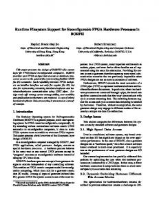
pattern is found in most multi-device computations. Applications present a wide range of data exchange sizes; for instance, waveguide simulation typically requires exchanging hundreds of kilobytes, fluid dynamics simulations tens of megabytes, and FFTs hundreds of megabytes. To account for these scenarios, experiments were run using data exchange sizes ranging from 256 KB to 256 MB. These benchmarks also evaluated the locking overhead required for multi-threaded device sharing. Experiments are run for different communication schemes (naive, pinned, double-buffered) implemented on CUDA with no HPE features (CUDA-base), and GMAC (HPE) with and without peer-DMA support. The performance of HPE was also measured using real-world applications. Current benchmark suites for GPUs like Parboil [13] and Rodinia [14] target singleGPU systems and do not stress data communication. Therefore, we have developed CUDA (using the previously mentioned communication schemes) and HPE versions of the following well-kown computations. We use a CPU thread for each GPU in the node. Each of these threads launches kernels on their assigned GPU but also access other GPUs to perform device↔device memory transfers when needed. 3D finite differences (stencil) is the driving example used in Section 2. 1D FFT application (fft) implements a Fast Fourier Transform on a 1D input vector using the Radix-2 CooleyTukey algorithm. This algorithm performs n steps in which different elements are combined. The combination pattern changes at each step and, therefore, in the multiGPU implementation, data must be exchanged between different pairs of GPUs at each step. We use the multiGPU implementation of mergesort found in [15]. The input vector is divided into chunks that are individually sorted by each GPU. Then, a swap phase merges the subvectors into a sorted vector whose contents are logically distributed among the memories of the GPUs. We have also developed two synthetic benchmarks to convey the benefits of the techniques implemented in our HPE runtime to optimize the communication with I/O devices. The first benchmark measures the time needed to transfer a file from disk to the GPU memory using four different implementations: user uses a regular user-level allocation to store the contents of the file and then transfer it to the GPU memory; pinned uses pinned memory instead of a user-level allocation; double-buffering uses two small pinned buffers to minimize the usage of pinned memory and to overlap the disk and GPU memory transfers. The second benchmark measures the time needed to send data across GPUs in different nodes through MPI. The following configurations are compared: user uses a regular user-level allocation to store the contents of the transfer before calling to send/ receive data from the network; pinned uses pinned memory instead (it exploits the GPUDirect technology that enables Infiniband interfaces to use the pinned memory allocated through CUDA); HPE uses two small pinned buffers to overlap network and CPU↔GPU transfers.
10
Transfer Size One-way HPE One-way CUDA-base
Two-way HPE Two-way CUDA-base
Fig. 8: CPU thread wait time for different inter-device data communication sizes. 5.2
Inter-device Data Transfers
Figure 7 (left) shows the one-way inter-device communication throughput delivered by each implementation for different communication sizes. Peer-DMA always delivers the highest throughput because there are no associated software communication overheads. Peer-DMA also delivers the highest throughput for two-way data exchange, as shown in Figure 7 (right). For a oneway communication, HPE with no peer-DMA support delivers 70% compared to hardware peer-DMA HPE for large data communication sizes due to the costs of performing intermediate copies to the host memory. However, Figure 7 (right) shows that the throughput delivered by hardware peer-DMA is almost 2× faster than the software emulated peer-DMA for a two-way data exchange. This additional performance penalty is due to contention for exclusive access to the source and destination GPU contexts, which are being used concurrently by all CPU threads. Figure 7 (left and right) also shows that the doublebuffering strategy is always the optimal software implementation. The benefit of double-buffering becomes noticeable for data communications larger than 1 MB, when double-buffering starts overlapping of host-todevice and device-to-host data transfers. The pinned implementation transfers all the data to a pinned buffer in host memory and, therefore, does not overlap data transfers. Still, the throughput delivered by this scheme is a 40% higher than the base implementation. Figure 8 shows the total wait time for HPE and CUDA-base Double-buffering. Locking time in HPE is
IEEE TRANSACTIONS ON PARALLEL AND DISTRIBUTED SYSTEMS, VOL. 25, NO. XX,XX 2014
1.7
2.8
1.7
1.6
2.6
1.6
2.4
1.5
1.3 1.2
Speedup (x)
1.4
2 1.8 1.6 1.4
1.1
CUDA-base Naive CUDA-base Pinned CUDA-base Double-buffering
HPE w/o peer DMA HPE w peer DMA
(a) 3D Stencil
1.3 1.2
1
1 2563 3843 5123 6403 7683 2563 3843 5123 6403 7683 2 GPUs 4 GPUs Elements
1.4
1.1
1.2
1 0.9
1.5
2.2 Speedup (x)
Speedup (x)
11
0.8
0.9 256KB
1MB
4MB
64MB 256MB
2 GPUs
256KB
4MB
64MB 256MB
4 GPUs
Vector Size
CUDA-base Naive CUDA-base Pinned CUDA-base Double-buffering
1MB
HPE w/o peer DMA HPE w peer DMA
(b) 1D FFT
216
218
220 222 2 GPUs
224
CUDA-base Naive CUDA-base Pinned CUDA-base Double-buffering
216
218
Elements
220 222 4 GPUs
224
HPE w peer DMA
(c) Mergesort
Fig. 9: Speedup over single GPU execution different input dataset sizes. shorter than in CUDA-base Double-buffering, except for two-way communication of small halo sizes. HPE only requires exclusive access to the GPU context for the duration of the API call that enqueues an asynchronous data transfer between the host and the device; after the DMA command has been requested to the hardware, the PCIe configuration registers can be used to request new DMA transactions. This is in contrast with the double-buffering implementation in CUDA-base, which requires exclusive access to the intermediate host buffer for the duration of each data transfer. For small size data transfers, the total time CUDA-base requires exclusive access to the intermediate buffer is short (few data is transferred) and, it shows a better behaviour than HPE. As the data communication size increases, CUDAbase requires locking the intermediate buffers for longer times, so the time each CPU thread waits to initiate the next data transfer increases. Inter-device data communication in HPE does not require waiting for any other CPU thread to bring the data to the intermediate host buffers. Hence, the lock time due to exclusive access to the GPU context only grows on the number of API calls required for the communication, which grows linearly with the data communication size. The smaller locking time for medium and large inter-device communication accounts for the extra throughput provided by HPE. 5.3
Application Benchmarks
Figure 9a shows the speedup of different implementations of stencil over the base CUDA-base version. In this application, boundaries are exchanged in every iteration with the left and right neighbors. Due to the limited support of remote accesses in current NVIDIA GPUs (only works for GPUs in the same PCIe bus), we use explicit data transfers in all the implementations. The points to be exchanged are computed first and are transferred concurrently with the rest of the computation, in order to hide the data transfer costs. The size of the data being transferred goes from 1 MB to 9 MB for the tested input datasets. Results show speedups that range from 1.04× to 1.23× for 2 GPUs and from 1.15× to 1.63× for 4 GPUs in the HPE version when peer-DMA is available. The largest improvements are obtained for small to medium input datasets, where the data transfer/computation ratio is high, as shown in Figure 10a. In these cases, the data
transfer cannot be completely masked. The improvement is greater in the 4-GPU configuration because, in the general case, each domain exchanges twice as data as the 2-GPU case and, therefore, the improvements in the memory transfers are more pronounced. The 1D FFT application is communication bound and, therefore, greatly benefits from the HPE model. As shown in Figure 10b, all configurations except HPE with peer-DMA support spend at least 86 % of the application time in data exchange routines, when using 2 GPUs and 87% for 4 GPUs. On hardware with peer-DMA, HPE exchange time is reduced to 80% for 2 GPUs and is at least 5% lower than the base implementation for 4 GPUs. This reduction results in speedups (see Figure 9b) that range from 1.58× to 2.6× for 2 GPUs over the naive CUDA 3 implementation and 1.17× to 1.61× for 4 GPUs. HPE with no peer-DMA support delivers speedups of 1.15× to 1.42× performance improvements over the base version for 2 GPUs and 1.01× to 1.6× for 4 GPUs (except for the smallest input dataset, since a single buffer is transferred). The performance of the double buffering implementation and HPE for 4 GPUs is closer because peer-DMA transfers across different PCIe buses are not currently supported, so intermediate copies are performed on the host memory. Moreover, the effect of the peer-DMA transfers is limited when using 4 GPUs because our FFT algorithm performs memory swaps between pairs of GPUs and these may be serialized if they involve the same GPU. Mergesort shows notable speedups when using HPE with peer-DMA transfers. This application swaps chunks of data between GPUs in order to merge the sorted subarrays into the final sorted array. When 4 GPUs are used, a first swap step is performed between GPUs 0 and 1 and GPUs 2 and 3 (to produce two sorted subarrays) and a final swap step is performed to merge them into the final array. Figure 9c reports speedups that range from 1.25× to 1.50× for 2 GPUs and 1.45× to 1.66× for 4 GPUs. This benchmark also benefits from remote accelerator memory access, but current hardware restricts the utilization of this mechanism to GPUs connected to the same PCIe bus. Remote memory accesses are used during the pivot search to determine which data needs to be exchanged between pairs of GPUs. Using remote memory accesses delivers much better performance than
IEEE TRANSACTIONS ON PARALLEL AND DISTRIBUTED SYSTEMS, VOL. 25, NO. XX,XX 2014
12
50
70
45
95
60
30 25 20 15
Percentage (%)
35
Percentage (%)
Percentage (%)
40 90
85
40 30 20
80
10
10
5 0
50
75
2563 3843 5123 6403 7683 2563 3843 5123 6403 7683 2 GPUs 4 GPUs Elements CUDA-base Naive CUDA-base Pinned CUDA-base Double-Buffering
0 256KB
1MB
4MB
64MB 256MB
2 GPUs
HPE w/o peer DMA HPE w peer DMA
256KB
4MB
64MB 256MB
216
4 GPUs
Vector Size
CUDA-base Naive CUDA-base Pinned CUDA-base Double-Buffering
(a) 3D Stencil
1MB
HPE w/o peer DMA HPE w peer DMA
218
220 222 2 GPUs
224
216
CUDA-base Naive CUDA-base Pinned CUDA-base Double-Buffering
(b) 1D FFT
218
Elements
220 222 4 GPUs
224
HPE w peer DMA
(c) Mergesort
Fig. 10: Percentage of time devoted to memory transfers over the total execution time.
5.4
Communication with I/O devices
The use of pinned memory is key for achieving fast transfers between I/O devices and the host memory. Pinned memory becomes even more important for transfers between devices (e.g., disk and GPU). Since these devices usually have their own private address spaces, they rely on intermediate copies to host memory for communication. If user-level memory allocations are used, the OS has to perform a number copies to/from these allocations to (system-managed) pinned buffers before starting a DMA transfer. Figure 11 shows that pinned memory is 2.2× to 2.7× faster than the base version. Overlapping some of the disk and GPU transfers provides even better performance (2.5× to 3.4×). HPE run-time matches the hand-tuned implementation (2.4× to 2.9×) while hiding the complexity of this technique. 3.5
Speedup (x)
3 2.5 2 1.5 1 0.5 4
8
16
32
64
128
256
Transfer Size (MB) User Pinned
Double-buffering HPE runtime
Fig. 11: Disk↔GPU transfer speedups of HPE compared to the base synchronous version. 5.5
Inter-node Communication (MPI)
Communicating GPUs across nodes requires moving data between the GPUs’ memories and the buffers in the network interfaces. While future systems will be able to perform P2P transfers between them, currently data has to be stored in host memory. Moreover, pinned memory must be used to avoid extra copies in the network interface driver. Figure 12 shows that using
pinned memory provides up to 2× better performance in GPU→GPU and GPU→host memory transfers, and up to 2.6× in host→GPU, than regular pageable allocations. Furthermore, the double-buffering implemented in HPE run-time for some MPI calls further improve the performance, providing speedups greater than 4×. D2D - Pinned D2H - Pinned H2D - Pinned
D2D - HPE D2H - HPE H2D - HPE
6 5 4 3 2 1 0 32 KB 64 KB 128 KB 256 KB 512 KB 1 MB 2 MB 4 MB 8 MB 16 MB 32 MB 64 MB 128 MB
Speedup (x)
copying the necessary data across GPUs (required by HPE when GPUs connected to different PCIe buses, and by CUDA 3). The percentage of time devoted to communication decreases as the dataset increases for 2 GPUs. The additional communication steps required in the 4 GPU implementation make the communication/ computation ratio increase with the input dataset size.
Fig. 12: MPI transfer speedups of HPE compared to the base synchronous version.
6
Related Work
Most research on system support for heterogeneous systems focuses on policies to manage the different properties (e.g., memory access latency) of heterogeneous processors and resource sharing (e.g., shared caches in many-core processors). The MIT Exokernel [16] supports heterogeneity by exposing the hardware diversity to user-level applications. The HPE model, like other highlevel abstractions, can be implemented as a user-level library on top of the MIT exokernel. The Infokernel [17] supports hardware diversity by providing abstractions that expose the internal OS kernel state to user-level. Rossbach et al [18] propose a new abstraction called PTask for processes that run on the accelerator and the addition of ports and channels to represent the communication graph among regular processes and PTasks. Using this scheme, unnecessary memory transfers among CPU and GPU memories can be avoided since the placement of memory objects is known to the system runtime. Moreover, more advanced scheduling policies can be implemented by taking advantage of the features provided by the accelerators in the system (e.g., concurrent GPU execution and memory transfers). However, this solution requires programmers to use new abstractions in their programs to support accelerators while HPE aims to simplify current abstractions to provide a model in which accelerators are used transparently.
IEEE TRANSACTIONS ON PARALLEL AND DISTRIBUTED SYSTEMS, VOL. 25, NO. XX,XX 2014
Language-based programming models have been proposed to deal with multiple accelerators, usually built on top of CUDA and-or OpenCL. Universal Parallel C (UPC) has been extended in [19] to transparently access data allocated in GPUs. UPC uses a Hybrid Partitioned Global Address Space in which each CPU thread is bound to one shared segment, that can be either in host memory or in GPU memory, but not both. Each thread is bound to the same memory segment during its lifetime. HPE allows a single CPU thread to manage several devices and devices to be shared among threads. Task-based runtimes allow transparent benefits from the parallelism of the system by dynamically scheduling tasks on all available processors/accelerators. Ayguad´e et. al. presented GPUSs in [20]. GPUSs relies on annotations to host functions and CUDA kernels, used by a source-to-source compiler to create a data dependency graph, that is used to schedule kernel execution, allocate memory and perform data copies among memories when necessary. Augonnet et. al. presented StarPU in [21], a library and runtime system for heterogeneous architectures. It provides data structures and functions to abstract the computational kernels as codelets and define dependencies among them. Input and output data handlers for codelets must be defined to automate data management. The runtime schedules codelets and performs the necessary memory copies. Programming models hide accelerator memories and expose a single address space to the programmer. Task-based runtimes can benefit from HPE’s ability of providing the best transfer scheme in different system organizations.
7
Conclusions
HPE greatly simplifies the task of programming multiaccelerator applications for heterogeneous parallel systems, by removing the need for applications to explicitly perform intermediate copies and complex synchronization patterns. We have implemented the HPE model and its associated techniques into GMAC, a user-level library that is publicly available at [11]. The techniques presented here, unified virtual address space based on segmentation, shadowed coherence buffers in asymmetric distributed shared memory, remote peer memory access, and peer DMA, as well as the CUDA devices that support some HPE features provided an opportunity for us to quantify the benefit of these features on real hardware. Experiments show that the HPE runtime transparently exploits devices that comes with hardware support for HPE features and significantly improves performance when such hardware is present in the system. We show that simple, portable application code based on HPE often achieves performance comparable to complex custom-written code even in systems that do not have good hardware support for HPE techniques. We have outlined the GPU hardware support required to efficiently implement the proposed UVAS. We further argue that without simple interfaces like HPE, the advanced
13
GPU hardware support will unlikely be used by most software applications in practice. Experimental results show that the HPE model eases programming of multi-accelerator applications while providing performance improvements of 2× compared to the best data transfer scheme implemented on top of CUDA 3. We have also analyzed the impact of HPE on three real benchmarks. Results show improvements that range from 5% in compute-bound benchmarks and up to 2.6× in communication-bound benchmarks. Finally, experiments show that HPE transparently implements sophisticated communication schemes that can deliver up to a 2.9× speedup in I/O device transfers.
Acknowledgments We thankfully acknowledge the support of the Spanish Ministry of Education (TIN2007-60625, TIN2012-34557 and CSD2007-00050), the Generalitat de Catalunya (2009SGR-980), the CUDA Centers of Excellence at UPC/BSC and at UIUC, the U.S. DoE Vancouver Project (DEFC02-10ER26004/DE-SC0005515), and the NIH funding through grants 9P41GM104601 and 5R01GM098243-02.
References [1] [2] [3] [4] [5] [6] [7]
[8] [9] [10] [11] [12] [13] [14]
[15] [16] [17]
S. Patel and W. W. Hwu, “Accelerator architectures,” IEEE Micro, vol. 28, no. 4, pp. 4–12, July-Aug. 2008. “TOP500 list - November 2011.” [Online]. Available: http://top500.org/list/2011/11/100 “Green500 list - November 2011.” [Online]. Available: http://www.green500.org/lists/2011/11/top/list.php AMD, “AMD fusion family of APUs: Enabling a superior, immersive pc experience,” 2010. J. Nickolls, I. Buck, M. Garland, and K. Skadron, “Scalable parallel programming with CUDA,” ACM Queue, vol. 6, no. 2, pp. 40–53, 2008. A. Munshi, The OpenCL Specification, 2009. I. Gelado, J. Stone, , J. Cabezas, S. Patel, N. Navarro, and W. W. Hwu, “An asymmetric distributed shared memory model for heterogeneous parallel systems,” in ASPLOS 2010. ACM, 2010, pp. 347 – 358. NVIDIA CUDA Programming Guide 5.0, 2011. P. Micikevicius, “3D finite difference computation on GPUs using CUDA,” in GPGPU’09. ACM, 2009, pp. 79–84. “NVIDIA GPUDirect,” https://developer.nvidia.com/gpudirect, NVIDIA. “GMAC: Global Memory for ACcelerators.” [Online]. Available: https://code.google.com/p/adsm/ S. Kato, M. McThrow, C. Maltzahn, and S. Brandt, “Gdev: Firstclass GPU resource management in the operating system,” in USENIX ATC, vol. 12, 2012. IMPACT Group, “Parboil benchmark suite,” http://impact.crhc.illinois.edu/parboil.php. S. Che, M. Boyer, J. Meng, D. Tarjan, J. W. Sheaffer, S.-H. Lee, and K. Skadron, “Rodinia: A benchmark suite for heterogeneous computing,” in IISWC ’09. IEEE Computer Society, 2009, pp. 44–54. I. Tanasic, L. Vilanova, M. Jord`a, J. Cabezas, I. Gelado, N. Navarro, and W.-m. Hwu, “Comparison based sorting for systems with multiple GPUs,” in GPGPU-6. ACM, 2013, pp. 1–11. D. R. Engler, M. F. Kaashoek, and J. O’Toole, Jr., “Exokernel: an operating system architecture for application-level resource management,” in SOSP ’95. ACM, 1995, pp. 251–266. A. C. Arpaci-Dusseau, R. H. Arpaci-Dusseau, N. C. Burnett, T. E. Denehy, T. J. Engle, H. S. Gunawi, J. A. Nugent, and F. I. Popovici, “Transforming policies into mechanisms with infokernel,” SIGOPS Oper. Syst. Rev., vol. 37, no. 5, pp. 90–105, 2003.
IEEE TRANSACTIONS ON PARALLEL AND DISTRIBUTED SYSTEMS, VOL. 25, NO. XX,XX 2014
[18] C. J. Rossbach, J. Currey, and E. Witchel, “Operating systems must support GPU abstractions,” in HotOS’13. USENIX Association, 2011, pp. 32–32. [19] Y. Zheng, C. Iancu, P. Hargrove, S.-J. Min, and K. Yelick, “Extending Unified Parallel C for GPU computing.” [20] E. Ayguad´e, R. M. Badia, F. D. Igual, J. Labarta, R. Mayo, and E. S. Quintana-Ort´ı, “An Extension of the StarSs Programming Model for Platforms with Multiple GPUs,” in Euro-Par ’09. SpringerVerlag, 2009, pp. 851–862. [21] C. Augonnet, S. Thibault, R. Namyst, and P.-A. Wacrenier, “StarPU: A Unified Platform for Task Scheduling on Heterogeneous Multicore Architectures,” in Euro-Par ’09, ser. Lecture Notes in Computer Science. Springer, 2009, pp. 863–874.
14
Nacho Navarro is Associate Professor at the ` Universitat Politecnica de Catalunya (UPC), Barcelona, Spain, since 1994, and Senior Researcher at the Barcelona Supercomputing Center (BSC). He holds a Ph.D. degree in Computer Science from UPC (1991), Spain. His current interests include: tools for evaluation of multi-core microprocessors, application-specific computer architectures, dynamic reconfigurable logic and resource management in heterogeneous environments and sensor networks. He is also doing research on the programmability and support of hardware accelerators like GPUs at the University of Illinois (IMPACT Research Group). Prof. Navarro is a member of the IEEE, the IEEE Computer Society, and the ACM.
Javier Cabezas is a Phd student in the Computer Architecture department at Universitat ` Politecnica de Catalunya (UPC) and works as researcher at the Barcelona Supercomputing Center (BSC). He received the B.S. and M.S. degrees in computer science from UPC, in 2006 and 2008, respectively. His research interests include computer architecture, parallel programming, GPU computing and Operating Systems. He is a student member of the IEEE.
Isaac Gelado is the lead researcher of the system software research group at NVIDIA. He received the B.S. (2001) annd M.S. (2003) degrees in telecommunications from the University of Valladolid. He holds a Ph.D. degree in ` Computer Science from Universitat Politecnica de Catalunya (2010). He has been a lecturer at UPC and a postdoctoral researcher at University of Illinois at Urbana-Champaign (UIUC) and at Barcelona Supercomputing Center (BSC). His research covers operating systems, parallel programming and architecture support for heterogeneous massivelyparallel computing systems. He is a member of the IEEE.
John E. Stone received the B.S. and M.S. degrees in computer science from the University of Missouri at Rolla, in 1994 and 1998, respectively. He is a Senior Research Programmer in the Theoretical and Computational Biophysics Group, Beckman Institute for Advanced Science and Technology, University of Illinois at UrbanaChampaign. He is also an associate director of the CUDA Center of Excellence at the University of Illinois at Urbana-Champaign. His research interests include scientific visualization, GPU computing (GPGPU), parallel rendering, immersive visualization, haptic interfaces for interactive simulation, and high-performance computing. He is a member of the IEEE and of the ACM.
David B. Kirk is an NVIDIA Fellow and served as NVIDIAs chief scientist from 1997 to 2009, a role in which he led the development of graphics technology for todays most popular consumer entertainment platforms. He also serves on the U.S. Commerce Departments Information Systems Technical Advisory Committee. Kirk was honored by the California Institute of Technology (Caltech) in 2009 with a Distinguished Alumni Award, its highest honor, for his work in the graphics-technology industry. In 2006, he was elected to the National Academy of Engineering in 2006 for his role in bringing high-performance graphics to PCs. He received the SIGGRAPH Computer Graphics Achievement Award in 2002 for his role in bringing HPC graphics systems to the mass market. Prior to NVIDIA, Kirk served from 1993 to 1996 as chief scientist and head of technology for Crystal Dynamics, a video game software development company. From 1989 to 1991, he was an engineer for the Apollo Systems Division of HP. Kirk is the inventor of more than 75 patents and patent applications relating to graphics design and has published many articles on graphics technology and parallel programming. He is also the author of the parallel programming textbook Programming Massively Parallel Processors, along with co-author Wen-mei Hwu. He holds BS and MS degrees in mechanical engineering from the Massachusetts Institute of Technology, and MS and PhD degrees in computer science from Caltech. He is a member of the IEEE.
IEEE TRANSACTIONS ON PARALLEL AND DISTRIBUTED SYSTEMS, VOL. 25, NO. XX,XX 2014
Wen-mei Hwu is the Walter J. (”Jerry”) Sanders III-Advanced Micro Devices Endowed Chair in Electrical and Computer Engineering in the Coordinated Science Laboratory of the University of Illinois at Urbana-Champaign. Dr. Hwu received his Ph.D. degree in Computer Science from the University of California, Berkeley, 1987. His research interests are in the areas of architecture,implementation,software for highperformance computer systems, and parallel processing. He is a Principal Investigator(PI) for the petascale Blue Waters system, is co-director of the Intel and Microsoft funded Universal Parallel Computing Research Center (UPCRC), and PI for the world’s first NVIDIA CUDA Center of Excellence. At the Illinois Coordinated Science Lab, he is the director of the OpenIMPACT project, which has delivered new compiler and computer architecture technologies to the computer industry since 1987. He also serves as the Soft Systems Theme leader of the MARCO/DARPA Gigascale Silicon Research Center (GSRC) and on the Executive Committees of both the GSRC and the MARCO/DARPA Center for Circuit and System Solutions (C2S2). For his contributions to the areas of compiler optimization and computer architecture, he received the 1993 Eta Kappa Nu Outstanding Young Electrical Engineer Award, the 1994 Xerox Award for Faculty Research, the 1994 University Scholar Award of the University of Illinois, the 1997 Eta Kappa Nu Holmes MacDonald Outstanding Teaching Award, the 1998 ACM SigArch Maurice Wilkes Award, the 1999 ACM Grace Murray Hopper Award, the 2001 Tau Beta Pi Daniel C. Drucker Eminent Faculty Award, and the 2002 ComputerWorld Honors Archive Medal. From 1997 to 1999, Prof. Hwu served as chairman of the Computer Engineering Program at the University of Illinois. In 2007 he introduced a new engineering course in massively parallel processing, which he co-taught with David Kirk, Chief Scientist of NVIDIA. In 2008, he was named co-director of one of two Universal Parallel Computing Research Centers sponsored by Microsoft and Intel. He is a fellow of IEEE and of the ACM.
15