check requestC ,AinCS,BinCS,CinCS,holding token in. 146 process ClientRequestAck [receive req ack1 ,receive req ack2 ,receive req ack3 ,all ack ]:. 147.
Runtime Conformance Checking of Mobile Agent Systems Using Executable Models
by
Ahmad A. Saifan
A thesis submitted to the School of Computing in conformity with the requirements for the degree of Doctoral of Philosophy
Queen’s University Kingston, Ontario, Canada April 2010
c Ahmad A. Saifan, 2010 Copyright °
Abstract Mobility occurs naturally in many distributed system applications such as telecommunications and electronic commerce. Mobility may reduce bandwidth consumption and coupling and increase flexibility. However, it seems that relatively little work has been done to support quality assurance techniques such as testing and verification of mobile systems. This thesis describes an approach for checking the conformance of a mobile, distributed application with respect to an executable model at runtime. The approach is based on kiltera — a novel, high-level language supporting the description and execution of models of concurrent, mobile, distributed, and timed computation. The approach allows distributed, rather than centralized, monitoring. However, it makes very few assumptions about the platform that the mobile agent system is implemented in. We have implemented our approach and validated it using four case studies. Two of them are examples of mobile agent systems, the two others are implementations of distributed algorithms. Our approach was able to detect seeded faults in the implementations. To check the effectiveness and the efficiency of our approach more comprehensively a mutation-based evaluation framework has been implemented. In this framework a set of a new mutation operators for mobile agent systems has been i
identified in order to automatically generate and run a number of mutants programs and then evaluate the ability of our approach to detect these mutants. We found that our approach is very effective and efficient in killing the non-equivalent mutants.
ii
Co-Authors Chapter 3 and part of Chapter 4 were published in paper co-authored with my supervisor Juergen Dingel and Ernesto Posse in the Proceedings of the 7th Workshop on Parallel and Distributed Systems: Testing, Analysis, and Debugging 2009 (PADTAD 2009) [75]. Parts of Chapter 1 and 2 are based on a paper previously published in the Proceeding of the International Joint Conferences on Computer, Information, System Sciences and Engineering (CISSE’08) [74] and in a Queen’s University technical report [73]. Both of them jointly authored with my supervisor Juergen Dingel.
iii
Statement of Originality I, Ahmad Saifan, certify that the work presented in this thesis is original unless otherwise noted. Any published (or unpublished) ideas and/or techniques from the work of others are fully acknowledged in accordance with the standard referencing practices.
iv
Acknowledgments First of all, I would like to express my heart-felt and most sincere gratitude to my respected supervisor Juergen Dingel for his guidance, advice, encouragement and extra ordinary patience during this thesis work. Without him, this work would have been impossible. I would like to thank Luigi Logrippo, Patrick Martin, Jenny Zou, and David Rappaport, the members of my thesis examination committee for their helpful comments and suggestions. I owe my parents any success I make in my life. Their encouragement, love and support is a key factor in any achievement I have ever made. I am also indebted to my beloved and incomparable wife, Doua, for more than I could ever express, due to her continuous encouragement, patience and support during the course of my Ph.D. program. I also thank the most wonderful thing of my life my children, Qusai and Yousef, for their patience and for the happiness and motivation I always find in their smiles. I want to thank my brothers, Amjad, Laith, and Ammar, and my sisters, for their love and support. I would like to thank all members of the School of Computing at Queens University for their support and friendship. Special thanks to Chanchal Roy and Jeremy Bradbury.
v
Table of Contents Abstract
i
Co-Authors
iii
Statement of Originality
iv
Acknowledgments
v
Table of Contents
vi
List of Tables
x
List of Figures
xi
Chapter 1: Introduction . . . . . . . . . . . . . . . . . . . . . . . . . .
1
1.1
Thesis and Scope of Research . . . . . . . . . . . . . . . . . . . . . .
2
1.2
Contributions . . . . . . . . . . . . . . . . . . . . . . . . . . . . . . .
4
1.3
Thesis Organization . . . . . . . . . . . . . . . . . . . . . . . . . . . .
5
Chapter 2: Background and Related Work . . . . . . . . . . . . . . .
7
2.1
Systems of Interest . . . . . . . . . . . . . . . . . . . . . . . . . . . .
7
2.1.1
7
Mobile Agent Systems . . . . . . . . . . . . . . . . . . . . . . vi
2.2
An Executable Modeling Language: kiltera . . . . . . . . . . . . . . .
11
2.2.1
Overview . . . . . . . . . . . . . . . . . . . . . . . . . . . . .
11
2.2.2
Simulation . . . . . . . . . . . . . . . . . . . . . . . . . . . . .
18
2.3
Aglets . . . . . . . . . . . . . . . . . . . . . . . . . . . . . . . . . . .
20
2.4
Related Work . . . . . . . . . . . . . . . . . . . . . . . . . . . . . . .
23
2.4.1
Model-Based Testing . . . . . . . . . . . . . . . . . . . . . . .
23
2.4.2
Runtime Monitoring . . . . . . . . . . . . . . . . . . . . . . .
25
2.4.3
Testing Mobile Code and Agent Systems . . . . . . . . . . . .
29
2.4.4
Program Mutation . . . . . . . . . . . . . . . . . . . . . . . .
30
Chapter Summary . . . . . . . . . . . . . . . . . . . . . . . . . . . .
31
Chapter 3: Description of Approach . . . . . . . . . . . . . . . . . . .
32
2.5
3.1
Proposed Approach . . . . . . . . . . . . . . . . . . . . . . . . . . . .
32
3.1.1
Construction of HLM . . . . . . . . . . . . . . . . . . . . . . .
34
3.1.2
Construction of KM from HLM
. . . . . . . . . . . . . . . . .
35
3.1.3
Instrumentation of IUT and KM using HLM . . . . . . . . . .
39
3.1.4
Execution of IUT and KM . . . . . . . . . . . . . . . . . . . .
41
Chapter Summary . . . . . . . . . . . . . . . . . . . . . . . . . . . .
41
Chapter 4: Case Studies . . . . . . . . . . . . . . . . . . . . . . . . . .
44
3.2
4.1
Case Study: Online Shopping Example . . . . . . . . . . . . . . . . .
45
4.1.1
General Description . . . . . . . . . . . . . . . . . . . . . . . .
45
4.1.2
Application of our Approach . . . . . . . . . . . . . . . . . . .
45
4.1.3
Checking sample properties . . . . . . . . . . . . . . . . . . .
55
4.1.4
Observations . . . . . . . . . . . . . . . . . . . . . . . . . . .
58
vii
4.2
Case Study: Contract Signing . . . . . . . . . . . . . . . . . . . . . .
59
4.2.1
General Description . . . . . . . . . . . . . . . . . . . . . . . .
59
4.2.2
Application of our Approach . . . . . . . . . . . . . . . . . . .
60
4.2.3
Checking Sample Properties . . . . . . . . . . . . . . . . . . .
70
4.2.4
Observations . . . . . . . . . . . . . . . . . . . . . . . . . . .
73
Other Examples . . . . . . . . . . . . . . . . . . . . . . . . . . . . . .
74
4.3.1
Token Ring Algorithm . . . . . . . . . . . . . . . . . . . . . .
74
4.3.2
Lamport Mutex Algorithm . . . . . . . . . . . . . . . . . . . .
76
Chapter Summary . . . . . . . . . . . . . . . . . . . . . . . . . . . .
78
Chapter 5: Mobile Agent Mutation Operators . . . . . . . . . . . . .
79
4.3
4.4
5.1
Motivation . . . . . . . . . . . . . . . . . . . . . . . . . . . . . . . . .
80
5.2
Mutation Operators for Mobile Agent Systems . . . . . . . . . . . . .
81
5.2.1
Mobility . . . . . . . . . . . . . . . . . . . . . . . . . . . . . .
81
5.2.2
Communication . . . . . . . . . . . . . . . . . . . . . . . . . .
86
5.2.3
Agent’s Run Method . . . . . . . . . . . . . . . . . . . . . . .
92
5.2.4
Agent Creation . . . . . . . . . . . . . . . . . . . . . . . . . .
94
5.2.5
Event Listeners . . . . . . . . . . . . . . . . . . . . . . . . . .
97
5.2.6
Agent Proxy . . . . . . . . . . . . . . . . . . . . . . . . . . . .
99
5.3
Chapter Summary . . . . . . . . . . . . . . . . . . . . . . . . . . . . 103
Chapter 6: Evaluation and Comparison . . . . . . . . . . . . . . . . . 104 6.1
The Evaluation Framework . . . . . . . . . . . . . . . . . . . . . . . . 105 6.1.1
Mutant Generation Phase . . . . . . . . . . . . . . . . . . . . 105
6.1.2
Evaluation Phase . . . . . . . . . . . . . . . . . . . . . . . . . 107 viii
6.2
6.3
Experimental Setup . . . . . . . . . . . . . . . . . . . . . . . . . . . . 108 6.2.1
Examples Used . . . . . . . . . . . . . . . . . . . . . . . . . . 108
6.2.2
Mutation Operators used . . . . . . . . . . . . . . . . . . . . . 110
Experimental Results . . . . . . . . . . . . . . . . . . . . . . . . . . . 110 6.3.1
Mutant Generation . . . . . . . . . . . . . . . . . . . . . . . . 110
6.3.2
Compile Mutants . . . . . . . . . . . . . . . . . . . . . . . . . 114
6.3.3
Run our Runtime Conformance Checking Approach . . . . . . 115
6.3.4
Detection Evaluation . . . . . . . . . . . . . . . . . . . . . . . 116
6.4
Comparison with Aspect-Oriented Runtime Monitoring . . . . . . . . 120
6.5
Chapter Summary . . . . . . . . . . . . . . . . . . . . . . . . . . . . 122
Chapter 7: Conclusion . . . . . . . . . . . . . . . . . . . . . . . . . . . 123 7.1
Summary . . . . . . . . . . . . . . . . . . . . . . . . . . . . . . . . . 123
7.2
Limitations and Future Work . . . . . . . . . . . . . . . . . . . . . . 125
Bibliography
. . . . . . . . . . . . . . . . . . . . . . . . . . . . . . . . . 128
Appendix A: The HLMs and the KMs of the Online Shopping Example
. . . . . . . . . . . . . . . . . . . . . . . . . . . . 141
Appendix B: The Kiltera Model of Lamport’s Mutex Algorithm with Instrumentation
. . . . . . . . . . . . . . . . . . . . . . 147
ix
List of Tables 2.1
Aglets callback methods . . . . . . . . . . . . . . . . . . . . . . . . .
4.1
Size in lines of code of the IUT and KM before and after the instrumentation . . . . . . . . . . . . . . . . . . . . . . . . . . . . . . . . .
4.2
23
58
Size in lines of code of the IUT and KM before and after the instrumentation of the contract example . . . . . . . . . . . . . . . . . . . .
73
5.1
Mobile agent mutation operators . . . . . . . . . . . . . . . . . . . .
82
6.1
Overview of the example programs . . . . . . . . . . . . . . . . . . . 109
6.2
The number of mutants generated for the two Aglets programs . . . . 111
6.3
Number of program mutants
6.4
Number of equivalent and killed mutants detected . . . . . . . . . . . 119
6.5
A comparison between our approach and aspect-oriented approach
. . . . . . . . . . . . . . . . . . . . . . 112
based on lines of code . . . . . . . . . . . . . . . . . . . . . . . . . . . 121
x
List of Figures 2.1
kiltera syntax . . . . . . . . . . . . . . . . . . . . . . . . . . . . . . .
13
2.2
An example in kiltera . . . . . . . . . . . . . . . . . . . . . . . . . . .
14
2.3
Mobility in kiltera . . . . . . . . . . . . . . . . . . . . . . . . . . . . .
16
2.4
Match and timeout statements in kiltera . . . . . . . . . . . . . . . .
18
2.5
An event trace of Example1 in Figure 2.2 . . . . . . . . . . . . . . . .
18
2.6
An event trace with real time mode . . . . . . . . . . . . . . . . . . .
20
2.7
Typical form of an agent in Aglets . . . . . . . . . . . . . . . . . . . .
22
3.1
Steps of our conformance testing approach . . . . . . . . . . . . . . .
33
3.2
A conditional interaction in standard Sequence Diagrams . . . . . . .
34
3.3
A simple Swimlaned Mobility Diagram (SMD) . . . . . . . . . . . . .
35
3.4
Message communication in kiltera . . . . . . . . . . . . . . . . . . . .
37
3.5
The kiltera model of the corresponding SMD presented in Fig. 3.3 . .
38
3.6
SMD with a check point . . . . . . . . . . . . . . . . . . . . . . . . .
39
3.7
Location of check point 1 in the IUT of agent P2 . . . . . . . . . . . .
40
3.8
Location of check point 1 in the KM of agent P2 . . . . . . . . . . . .
40
3.9
Code inserted into the IUT of agent P2 at check point 1 . . . . . . . .
40
3.10 Code inserted into KM of agent P2 at check point 1 . . . . . . . . . .
41
3.11 The architecture of the monitoring infrastructure . . . . . . . . . . .
42
xi
4.1
The SMD of overall online shopping system . . . . . . . . . . . . . . .
46
4.2
The SMD of the initialization process . . . . . . . . . . . . . . . . . .
47
4.3
The SMD of the client . . . . . . . . . . . . . . . . . . . . . . . . . .
48
4.4
The SMD of the agent . . . . . . . . . . . . . . . . . . . . . . . . . .
49
4.5
The KM of the initialization process of the shopping example . . . . .
50
4.6
The KM of the client . . . . . . . . . . . . . . . . . . . . . . . . . . .
50
4.7
The Agent KM . . . . . . . . . . . . . . . . . . . . . . . . . . . . . .
51
4.8
Check points locations in camera searcher scenario SMD . . . . . . .
53
4.9
Location of check point 5 in the IUT . . . . . . . . . . . . . . . . . .
54
4.10 Location of check point 5 in the KM . . . . . . . . . . . . . . . . . . .
54
4.11 Code inserted into IUT at check point 5 . . . . . . . . . . . . . . . . .
55
4.12 Code inserted into KM at check point 5 . . . . . . . . . . . . . . . . .
55
4.13 Checking Property 2 in KM . . . . . . . . . . . . . . . . . . . . . . .
57
4.14 Checking Property 3 in KM . . . . . . . . . . . . . . . . . . . . . . .
58
4.15 The SMD of the overall contract signing example . . . . . . . . . . .
61
4.16 The SMD of the notary . . . . . . . . . . . . . . . . . . . . . . . . . .
62
4.17 The SMD of the contract . . . . . . . . . . . . . . . . . . . . . . . . .
63
4.18 The SMD of the Partner1 . . . . . . . . . . . . . . . . . . . . . . . .
64
4.19 The KM of the notary . . . . . . . . . . . . . . . . . . . . . . . . . .
65
4.20 The KM of the contract . . . . . . . . . . . . . . . . . . . . . . . . . .
66
4.21 The KM of the Partner1 . . . . . . . . . . . . . . . . . . . . . . . . .
67
4.22 Check points locations in SMD of signing a contract scenario . . . . .
69
4.23 Location of check point 3 in the IUT . . . . . . . . . . . . . . . . . .
70
4.24 Location of check point 3 in the KM . . . . . . . . . . . . . . . . . . .
70
xii
4.25 Code inserted into IUT at check point 3 . . . . . . . . . . . . . . . . .
71
4.26 Code inserted into KM at check point 3 . . . . . . . . . . . . . . . . .
71
4.27 Checking Property 1 in KM . . . . . . . . . . . . . . . . . . . . . . .
72
4.28 Checking Property 2 in KM . . . . . . . . . . . . . . . . . . . . . . .
72
4.29 Checking Property 3 in KM . . . . . . . . . . . . . . . . . . . . . . .
73
4.30 KM of token ring algorithm . . . . . . . . . . . . . . . . . . . . . . .
75
4.31 Checking entering the CS in token ring algorithm using KM . . . . .
76
4.32 Checking releasing the CS in Lamport algorithm using KM . . . . . .
77
6.1
The mutation-based evaluation framework . . . . . . . . . . . . . . . 106
6.2
The number of mutants per operator category . . . . . . . . . . . . . 113
6.3
The number of mutants per Java file grouped in ranges . . . . . . . . 114
6.4
The number of mutants per Java file against lines of code . . . . . . . 115
6.5
Kiltera output . . . . . . . . . . . . . . . . . . . . . . . . . . . . . . . 116
6.6
Part of the analysis report . . . . . . . . . . . . . . . . . . . . . . . . 118
A.1 The SMD of overall online shopping system . . . . . . . . . . . . . . . 142 A.2 The SMD of the initialization process . . . . . . . . . . . . . . . . . . 142 A.3 The SMD of the client . . . . . . . . . . . . . . . . . . . . . . . . . . 143 A.4 The SMD of the Mall1 with two shops . . . . . . . . . . . . . . . . . 143 A.5 The SMD of the agent . . . . . . . . . . . . . . . . . . . . . . . . . . 144 A.6 The KM of the initialization process of the shopping example . . . . . 144 A.7 The KM of the client . . . . . . . . . . . . . . . . . . . . . . . . . . . 145 A.8 The KM of the Mall1with two shops . . . . . . . . . . . . . . . . . . . 145 A.9 The Agent KM . . . . . . . . . . . . . . . . . . . . . . . . . . . . . . 146
xiii
Chapter 1 Introduction Software quality is an important attribute that all developers of software systems want to achieve. Moreover, the size and complexity of software systems is increasing in general. Mobile Agent Systems (MAS) are no exception. MAS are a special kind of distributed system. In MAS, the code of the agent has the capability to move from one host to another. More precisely, code mobility refers to the “capability to reconfigure dynamically, at run-time, the binding between the software components of the application and their physical location within a computer network” [18]. Mobility occurs naturally in many distributed system applications such as telecommunications and electronic commerce. Moreover, mobility may reduce bandwidth consumption and coupling and increase flexibility [70]. The use of mobility has reached a certain degree of maturity: several different development platforms are available (e.g., Aglets [49, 3], Voyager [2], and Grasshopper [9]) and comparative performance evaluations have been conducted [85]; agent-oriented software engineering (AOSE) has produced tool-supported development methodologies (e.g., Prometheus [68]) and Tropos [15]); promising commercial applications exist [62], and 1
CHAPTER 1. INTRODUCTION
2
standardization is being considered [69]. However, it seems that relatively little work has been done to support quality assurance techniques such as testing and verification of mobile systems [26, 89]. There are several characteristics of mobile agent systems that make testing a challenging task. Some of these characteristics include mobility, autonomy, distribution.
1.1
Thesis and Scope of Research
The common way to validate the quality of software systems is testing. The primary goal for this thesis is to provide an approach to improve the quality of mobile agent systems. Our approach will take the benefits of the kiltera high-level programming language in order to build a prototype that allows the validation of these kinds of systems.
Thesis Statement: Using an executable modeling language for mobile, distributed and timed systems such as kiltera, runtime conformance testing of realistic mobile applications can be implemented effectively and efficiently.
In this thesis, we present an approach for checking the conformance of a mobile application with respect to an executable model at runtime. The approach is based on a novel high-level modeling language for mobile, distributed, and timed systems called kiltera [71]. Application of the approach starts with the creation of a high-level model of the system using, e.g., a UML profile; the high-level model is assumed to capture correctly the most relevant aspects of the system behavior such as descriptions of the movement of agents, their interaction with hosts and other agents, and any results
CHAPTER 1. INTRODUCTION
3
computed. Next, the high-level model is translated into a kiltera model; kiltera’s direct support for many relevant features (e.g., support for concurrency with (a)synchronous message passing, movement of processes, and time- and site-dependent behavior) makes this translation relatively straight-forward. The high-level model is then used to identify suitable “check points” at which conformance between the implementation under test and the kiltera model is to be checked; check points typically occur right before or after the sending or receipt of messages or agent movement; after these check points have been located in the implementation under test and the kiltera model, both are instrumented at these check points to allow relevant information to flow from the implementation under test to the kiltera model. During the last step of our approach, the implementation under test and the kiltera model are executed, both possibly in a distributed fashion. The kiltera model will report any non-conformance that arises during execution. Our work benefits from the fact that kiltera allows a succinct, accessible expression of many features of mobile and distributed systems. Moreover, model debugging and analysis is possible using kiltera’s simulation environment. Finally, our approach does not assume a central monitoring component; instead, the kiltera model can be arbitrarily distributed, just like the implementation under test, which helps reduce any performance penalty. We have implemented the approach in a prototype and evaluated using a mutation-based evaluation framework. The scope of our research is constrained by the following: • In this thesis, we will assume that the mobile agent system has been implemented using the Aglets platform [49, 3]. However, since our approach makes
CHAPTER 1. INTRODUCTION
4
relatively few assumptions about the agent platform, application of our approach to implementations using other agent languages should be straightforward. • In our approach, we do not consider test case generation at all. In other words, we assume that test cases are given and provide no way of generating them. While the generation of test cases from the kiltera model is possible, we leave this for future work. • Our approach will assume the correctness of the model and the instrumentation necessary for monitoring. However, the executability of the models mitigates this assumption by allowing model debugging and analysis.
1.2
Contributions
The contributions of this thesis are the following: • The development of an approach for automatically checking conformance of a mobile, distributed, timed application with respect to an executable model at runtime. The approach supports distributed monitoring, offers the benefits of formal, yet executable models and is relatively independent of the agent platform used. • The design, implementation and evaluation of a prototype implementing the approach. • The development of a set of new mutation operators for mobile agent systems implemented in Aglets. The purpose of these operators is to insert bugs in the
CHAPTER 1. INTRODUCTION
5
system under test that most of the programmers may make when they implement a mobile agent system. Our experiments confirm that the vast majority of the mutants generated using the approach are non-equivalent. • The development and implementation of a mutation-based evaluation framework that is used to check the efficiency and the effectiveness of the proposed approach. In this framework the mutants are automatically generated from the system under test using the mutation operators and our analysis prototype is used to determine their conformance to a kiltera model.
1.3
Thesis Organization
In this chapter we have motivated and presented the research problem of testing mobile agent systems at runtime. Moreover, we presented the scope and the contribution of this thesis. The remaining chapters of the thesis are organized as follows: • Chapter 2: This chapter presents relevant background and related work. • Chapter 3: This chapter describes in detail the four steps of our approach for checking the conformance of a mobile agent application with respect to an executable model at runtime. • Chapter 4: In this chapter, we apply our proposed approach to four case studies. Two of them are examples of mobile agent systems, the two others are implementations of distributed algorithms. • Chapter 5: This chapter overviews a set of new mutation operators for mobile
CHAPTER 1. INTRODUCTION
6
agent systems. These mutation operators are used in the mutation-based evaluation framework in order to check the efficiency and the effectiveness of our approach. • Chapter 6: In this chapter, we describe the mutation-based evaluation framework. Specifically we outline the steps of this framework and present the results of experiments using our approach. Moreover, details on the comparison of our runtime conformance checking approach with another monitoring approach are given. • Chapter 7: Finally, this chapter concludes the thesis along with some discussion of the limitations and future work of our runtime conformance checking approach.
Chapter 2 Background and Related Work This chapter begins with presenting the systems that we are interested in this thesis (Section 2.1). We give a definition of distributed systems and challenges of testing these systems. Moreover, we provide a definition of software agent and mobile agent systems. In Section 2.2, kiltera, the executable high-level language is described in detail. Section 2.3 describes the mobile agent framework Aglets. Solutions that are strongly related to our work are presented in Section 2.4. Section 2.5 summarizes the chapter.
2.1
Systems of Interest
2.1.1
Mobile Agent Systems
Because mobile agent systems are a special kind of distributed system, we first discuss these systems and the challenges of testing this kind of system. There are several definitions of a distributed system. For example, Coulouris 7
CHAPTER 2. BACKGROUND AND RELATED WORK
8
et al [25] define a distributed system as “a system in which hardware or software components located at networked computers communicate and coordinate their actions only by message passing”. Tanenbaum and Steen [82] define it as “a collection of independent computers that appear to the users of the system as a single computer”. Distributed systems consist of a number of independent components running concurrently on different machines that interact with each other through communication networks to meet a common goal. In other words, in distributed systems the components are autonomous, i.e, they possess full control over their parts at all times. The components, however, have to take into account that they are being used by other components and have to react properly to requests. There are multiple points of failure in a distributed system. Distributed systems could fail because a component of the system has failed. Moreover, network communication is not always successful (transmission errors) and sometimes messages do not arrive on time. In real-time systems, for example, if the deadlines of the operations are not met, serious consequences may occur. Often, fault tolerance mechanisms must be used to ensure that these problems do not result in failure of the overall system. Moreover, when many network messages are transmitted over a particular network, the performance of the communication may deteriorate. In summary, all of these aspects severely complicate the correct design and implementation of distributed systems. Testing distributed systems is a difficult and challenging task. It is much more difficult to test a distributed system than to test a sequential program. For sequential programs, we can say that the program is correct when its inputs produce correct outputs according to its specification. However, in distributed systems correctness of the input-output relationship of a single process alone does not imply the correctness
CHAPTER 2. BACKGROUND AND RELATED WORK
9
of the entire system, because components have an ongoing interaction and the system could enter an improper state even if each process has the correct input-output relationship. Apart from the potential for non determinism and failure due to this ongoing interaction, there are many other characteristics of distributed systems that make testing of this kind of system difficult. Typically, distributed systems are heterogeneous in terms of communication networks, operating systems, hardware platforms and also the programming language used to develop individual components. This means that the system should be able to run over a wide variety of different platforms and access different kinds of interfaces. Moreover, the size and complexity of distributed systems is growing dramatically which complicates testing further. Nonetheless, because distributed systems are used in many critical applications in banks, hospitals, businesses, offices, etc, finding effective and efficient tetsing techniques for distributed systems are more important than ever. Software Agents From the software engineering point of view a software agent is : “a software entity which functions continuously and autonomously in a particular environment, often inhabited by other agents and processes” [80]. There are different forms or types of software agents [63, 81, 8]: autonomous (agents are dynamic entities and can make a decision on their own), proactive (agents do not just follow the rules but it also depends on the internal state of the agent), intelligent (agents have the ability to learn and adapt according to the situations based on previous experience), cooperative (collaborate with other agents), distributed (agents can be executed as independent
CHAPTER 2. BACKGROUND AND RELATED WORK
10
threads and on distributed processors) or mobile (the agent can move from one platform to another carrying its state, data, and code). Mobile Agent Technology Mobile Agent Systems (MASs) are a special kind of distributed system and “have been introduced as a key enabler of distributed computing” [8]. In MAS, the code of the agent has the capability to move from one host to another. Code mobility refers to the “capability to reconfigure dynamically, at runtime, the binding between the software components of the application and their physical location within a computer network” [18]. Mobile agents have been developed to extend or to enhance the functionality and the operations of the client-server paradigm [42, 72, 36]. Mobility may reduce bandwidth consumption and coupling and increase flexibility [70]. Mobility occurs naturally in many distributed system applications such as telecommunications and electronic commerce. In [5], Far states that “nowadays, an increasing number of software projects are being revised and restructured in terms of multi-agent systems”. In addition to the potential for failures in distributed systems, the following additional failures may occur in mobile agent systems. The agent could be killed incorrectly by other agent. The agent could be lost if for example it is moved to an incorrect address. Furthermore, sometimes the agent loses the connection with other agents or it is moved under the wrong circumstances. To conclude, testing MASs is a complex and challenging task. Weyns and Georgeff [87] mentioned in a recent paper (January 2010) that “as with any distributed system, testing a multiagent system is challenging. Decentralization and development in an open environment add to the complexity”.
CHAPTER 2. BACKGROUND AND RELATED WORK
2.2
11
An Executable Modeling Language: kiltera
kiltera developed by Poss [71] is a language used to describe the behavior of timed, concurrent, interacting processes which may be distributed over several sites. It provides operators to compose processes in parallel, to describe communication via events, or equivalently via message-passing over channels, to limit the scope of events, to delay processes and to observe the passage of time, as well as to move processes to remote sites. The core of the language is a process algebra which it is called πklt , an extension of the π-calculus [59]. Unlike other basic process algebras, kiltera provides some higher-level constructs to facilitate development. In particular, kiltera allows the use of complex expressions and data-structures in messages, and uses pattern-matching as a mechanism to extract information from data. The language has a formal semantics and a meta-theory (see [71]) which serve as the basis for the formal analysis of models. Furthermore, it has been implemented, supporting both uniprocessor and truly distributed simulation. In the following we introduce informally a significant subset of the language and provide a brief description of the simulator.
2.2.1
Overview
A model or specification in kiltera consists of one or more modules, the smallest “movable” processing unit. Each module has the syntax:
module A[˜ x](˜ y) : P
or
module A[˜ x](˜ y ) : sites s˜ in P
CHAPTER 2. BACKGROUND AND RELATED WORK
12
Here P ranges over process terms, defined below. We use x, xi , ... for port/channel/event names, and A, B, ... for process/module names, s, si for site names, and y, yi , ... for any other variable name. The notation x˜ denotes a list of names or values x1 , ..., xn . In the definition of a module, the names x˜ represent the interface of the module, that is, its ports, or equivalently, the events which it can use to communicate with other modules. The names y˜ represent local state variables and the (optional) s˜ represents the names of sites known by this module. The process body P is a process term which describes the structure and behavior of the module. The syntax for process terms P is shown in Figure 2.1 on page 131 . Here E ranges over expressions, F ranges over patterns, op ∈ {+, −, ∗, /, mod, and, or, not, , = , =, ! =}, n ranges over floating point numbers, s ranges over strings, x ranges over variable names, and f ranges over function names, with function definitions having the form: function f (˜ x) : E. The process done simply terminates. The term “trigger x with E” triggers an event x and associates this event with the value of expression E. Alternatively, one can say that it sends the message E through channel x (a channel and an event are synonymous). The expression E is optional. This process performs communication by unicasting: if there are multiple listeners, only one of them accepts the message, and the choice is non-deterministic. 1
In the presentation of the syntax we use braces { and } to denote syntactic nesting for the par and seq operators, but in the actual implementation and the examples we use indentation-based nesting.
CHAPTER 2. BACKGROUND AND RELATED WORK
P ::= | | | | | | | | | | β ::= E ::= | F ::= |
13
done trigger x with E when β1 → P1 | · · · | βn → Pn event x˜ in P wait E → P par {P1 , ..., Pn } process A[˜ x](˜ y ) : P1 in P2 ˜ A[˜ x](E) move A[˜ x](˜ y ) to s here s in P dchannel x˜ in P x with F after y n | true | false | “s” | x | op E E1 op E2 | f (E1 , ..., Em ) | (E1 , ..., Em ) n | true | false | “s” | x (F1 , ..., Fm ) Figure 2.1: kiltera syntax
Example 1: Figure 2.2 represents an example in kiltera where the name of the module is Example12 . Two processes are defined within this module: Sender and Receiver. Each of these two processes has one port x_ch and y_ch respectively. The definitions of these two processes are valid within the scope that is defined in lines 10-14 using the word in . In this scope, we create two instances of the two processes that are executing in parallel and are connected through the channel (event) a_ch. Lines 3-4 represent the body of the Sender process and lines 7-9 represent the body of Receiver process. A process can trigger events and can react to events. In line 3, the Sender process triggers an event x_ch and sends ‘‘message’’ as data along with this event. Then, the process terminates (line 4). In line 7, the Receiver process listens to the occurrence of the event (through event y_ch) and binds the received value to the variable 2
Note that this module does not have any ports that are used to communicate with other modules.
CHAPTER 2. BACKGROUND AND RELATED WORK
14
data. When the Receiver process receives the message, it prints the received value (line 8) and terminates (line 9).
1 2 3 4
module Example1 [ ] : process Sen der [ x c h ] : t r i g g e r x c h with ‘ ‘ message ’ ’ done
5 6 7 8 9 10 11 12 13 14
process R e c e i v e r [ y c h ] : when y c h with data −> print data done in channel a c h in par Sen der [ a c h ] Receiver [ a ch ]
Figure 2.2: An example in kiltera Channel mobility is achieved in the same way as in the π-calculus since event/channel names are expressions, and so they can be sent to other processes as messages. The process “when β1 → P1 | · · · | βn → Pn ” is a listener, consisting of a list of alternative input guarded processes βi → Pi . Each input guard βi is of the form “xi with Fi after yi ”, where xi is an event/channel name, Fi is a pattern, and yi is a variable (the suffixes “with F ” and “after y” are optional). This process listens to all events (channels) xi , and when xi is triggered with a value v that matches the pattern Fi , the corresponding process Pi is executed with yi bound to the amount of time that the listener waited, and the alternatives are discarded 3 . A listener process represents, thus, a process in a state with external choice. Pattern-matching of inputs means that the input value must have the same “shape” as the pattern, and if successful, the free names in the pattern are bound to the corresponding values of the 3
Note that to enable an input guard it is not enough for the event to be triggered: the event’s value must match the guard’s pattern as well.
CHAPTER 2. BACKGROUND AND RELATED WORK
15
input. For example, the value (3, true, 7) matches the pattern (3, x, y) with the resulting binding {x 7→ true, y 7→ 7}. The scope of these bindings is the corresponding Pi .4 The process “event x˜ in P ”, also written “channel x˜ in P ”, hides the names x˜ from the environment, so that they are private to P . Alternatively, we can say that it creates new events/channels x˜ whose scope is P . The process “wait E → P ” delays the execution of process P by an amount of time equal to the value of the expression E. The process “par {P1 , ..., Pn }” is the parallel composition of P1 , ..., Pn . The process “process A[˜ x](˜ y ) : P1 in P2 ” declares a new process definition A with ports x˜, (optional) state variables y˜ and body P1 . The scope of this definition is the ˜ creates a new instance of a process (or module) process P2 . The term “A[˜ x](E)” named A, whose definition is in the current scope, where the ports x˜ and variables y˜ of the definitions are substituted in the body of A by the events or channels x˜ and the values of E˜ respectively. The process “move A[˜ x](˜ y ) to s” creates an instance of the process defined by module A in site s. The process “here s in P ” binds the name of the local site to s in P . Finally, the process “dchannel x˜ in P ” creates a channel to communicate with modules on remote sites. Note that modules are essentially the same as process definitions, except that they do not have a surrounding lexical context and therefore are self-contained, since their only external references are its ports. This is why we only allow modules to be moved to other sites. Example 2: Figure 2.3 represents an example in kiltera where the name of the module is Example2. This module has one port module_port_connection used to connect this module with other modules. Moreover, this module has two processes P1 and P2. 4
This is essentially the same as pattern-matching in functional languages like ML or Haskell.
CHAPTER 2. BACKGROUND AND RELATED WORK
1 2 3 4 5 6 7 8 9
16
module Example2 [ m o d u l e p o r t c o n n e c t i o n ] s i t e s A, B process P1 [ x c h ] : channel r e s p o n s e c h in wait 50 −> seq trigger x chwith ( ‘ ‘ create ’ ’ , r e s p o n s e c h ) . when r e s p o n s e c h with r e s u l t −> // Do s o m e t h i n g w i t h r e s u l t
10 11 12 13 14 15 16 17 18 19 20
process P2 [ x c h ] : when x c h with ( data , r e s p o n s e c h ) −> par move Agent [ m o d u l e p o r t c o n n e c t i o n ] to B t r i g g e r r e s p o n s e c h with ‘ ‘ c r e a t e d ’ ’ . in channel z c h in par P1 [ z c h ] P2 [ z c h ]
Figure 2.3: Mobility in kiltera Lines 4-9 represent the body of process P1 and lines 12-15 represent the body of process P2. There are two sites known by this module A and B (line 2). These sites are used to identify the location that a process is in since each process executes in a site. In process P1, a new channel response_ch has been created (line 4). The scope of this channel are the lines 5-9. Line 5 makes the process P1 to wait for 50 seconds. After that the lines 6-9 will be executed. The sequential composition operator seq in line 6 executes the statements in lines 7-8 sequentially. Line 7 represents an example of channel mobility, where the tuple (‘‘create’’, response_ch) is sent as a message through the channel x_ch. Here, response_ch is a mobile channel and is sent as a message. In line 12, process P2 will receive the message through channel x_ch because the tuple (‘‘create’’, response_ch) matches the pattern (data, response_ch). The parallel composition operator par in line 13 executes
CHAPTER 2. BACKGROUND AND RELATED WORK
17
the statements in lines 14-15 concurrently. In line 14, we create an instance of module Agent at site B and allow communication with module Example2 through the channel module_port_connection. In line 15, process P2 sends a response to process P1 with the message “created” through the mobile channel reponse_ch. There are several derived process terms, such as sequential composition, timeouts, conditionals, etc. Here we only mention a few of them. The process term “when β1 → P1 | · · · | βn → Pn timeout E → P ” associates a timeout with a listener. If after an amount of time determined by the value of the expression E none of the events have been triggered, control passes to P . The process “match E with F1 → P1 | · · · |Fn → Pn ” evaluates the expression E and attempts to match it with each pattern Fi . If a pattern Fi matches then the corresponding process Pi is executed. If more than one pattern matches the choice is non-deterministic. The process “if E then P else Q” is shorthand for match E with true → P |false → Q. Finally, we also have terms of the form “let y = E in P ” which define local names in a process P . Example 3: Figure 2.4 shows two examples in kiltera. The first one shows the match statement and the other shows the timeout statement. In Figure 2.4 (a) we are using the match statement to check whether the Queue is empty or not. If the Queue is empty (line 2) the process will terminate (line 3). Otherwise, the head of the Queue will be assigned to the variable head and the remainder of it will be assigned to the variable remainder. In Figure 2.4 (b) the process waits for an event a_ch for an amount of time equal to the value of t. If the event occurs before this amount of time, ‘‘data received’’ (line 2) will be printed and the statement print ‘‘TimeOut’’
CHAPTER 2. BACKGROUND AND RELATED WORK
18
is discarded. If the event does not occur in this amount of time, the statement in line 2 is discarded and TimeOut will be printed. (a): match ————————————————— 1 2 3 4 5
(b): timeout ————————————————
match Queue with when a c h with data−> [ ] −> print ‘ ‘ data r e c e i v e d ’ ’ . done timeout t −> | [ head , r e m a i n d e r ] −> print ‘ ‘ TimeOut ’ ’ . // do s o m e t h i n g w i t h t h e head o f t h e Queue
—————————————————
————————————————
Figure 2.4: Match and timeout statements in kiltera
2.2.2
Simulation
The implementation of kiltera supports both uniprocessor and truly distributed simulation. Both are based on event scheduling. The basic idea is that each term in the language is treated as a simulation event to be executed by the event-scheduler (and not to be confused with a communication event in the language itself). The result of a simulation is a detailed event trace. Figure 2.5 shows an event trace of Example1 in Figure 2.2.
Figure 2.5: An event trace of Example1 in Figure 2.2
The event-scheduler contains a queue of simulation events (terms) to be executed,
CHAPTER 2. BACKGROUND AND RELATED WORK
19
but rather than store them all in a single linear queue, kiltera divides them into timeslots, i.e., sequences of all simulation events to be executed at a given instant in time. Hence the global event queue is a time-ordered queue of time-slots, each of which is a queue of terms. Execution proceeds by taking the first time-slot in the queue, taking the first term in the time-slot and performing its action. Once the first time-slot becomes empty, the simulator proceeds to the next time-slot. Each action executed depends on the specific construct.
The par construct
for example, simply adds the subterms to the current time-slot. The action for event creates a new communication event object in the heap. Interaction is done by means of the observer design pattern. The action for a when creates a listener for the appropriate events and registers them with the corresponding event objects. The trigger construct notifies the communication event object, which then selects one of its listeners and executes the corresponding continuation (while discarding other branches of the original listener). The delay construct wait simply adds the term in the appropriate time-slot of the global queue. The kiltera simulator supports two modes: realtime and logical time. In real time mode, once the current time slot becomes empty, the simulator actually pauses and waits until the time associated with the next time slot has been reached. In logical time mode, once the current time slot becomes empty, a logical global clock is set to the time of the next time slot and execution resumes immediately. Figure 2.6 shows an event trace of an updated version of Example1 in Figure 2.2 executed in real time mode by adding the statement “wait 5->” between lines 2 and 3). Distributed simulation in kiltera is achieved using the TimeWarp algorithm [43]. Briefly, this is an optimistic simulation algorithm, where multiple event-schedulers
CHAPTER 2. BACKGROUND AND RELATED WORK
20
Figure 2.6: An event trace with real time mode
(such as the one described above) run on different sites, but rather than blocking to wait for external messages, each simulator proceeds as fast as it can, and whenever an external message arrives, its time-stamp is compared with the local clock (the time of the first time-slot). If the external message has a future time-stamp relative to the local time, it is simply scheduled. If it is in the past, then the simulator rolls back to a time before the message’s time. This algorithm is guaranteed to yield the same behavior of a single global event-scheduler. In the case of kiltera whenever we move a module to a remote site we send a copy of the module to that site (the IP address for the site is specified in a configuration file). The site must be running a daemon which, whenever it receives a module, starts a new simulator locally which runs the newly arrived module. Each simulator executes the TimeWarp algorithm, and has a “dchannel” manager to handle remote communications through the dchannels created locally.
2.3
Aglets
The Aglets Software Development Kit (ASDK) [49, 3] is a framework and environment for developing and running mobile agents. It was originally developed at the IBM
CHAPTER 2. BACKGROUND AND RELATED WORK
21
Tokyo Research Laboratory. The Aglets system is one of the most popular Javabased open source mobile agent systems [34, 50, 85]. The ASDK includes Aglets API packages, documentation, sample Aglets, and the Tahiti Server. Tahiti is a Java application that allows a user to receive, manage, and send aglets to other computers that are running Tahiti [67]. The execution environment for Aglets is called context. An Aglet is created, exists, works, sleeps, and dies in such a context. An Aglet is a Java agent able to autonomously and spontaneously move from one context to another. In Aglets, the agent starts its work by executing its run() method. Furthermore, it can double itself by using the clone() method. It can migrate from one context to another using the dispatch() method. The retract() method requests a destination agent system to send the specified agent back to the sender. Also, the agent can destroy itself using the dispose() method. In Aglets, agents can communicate with each other by exchanging messages using the sendMessage() method. When a message is sent to an agent, its handleMessage() method is called so that the agent receives the message. Figure 2.7 shows the general form of an agent in Aglets. Before any major event in an agent’s life, a callback method is invoked to allow the agent to prepare for the event. Aglets support several of these callback methods. These callbacks can be overridden in order to customize the behavior of an agent. The Aglet’s callback methods are summarized in Table 2.1. For more information, see [49, 3]. Based on these methods, Aglets support three kinds of event. These events are discussed in [30]. As presented in the Aglets manual [30]:
CHAPTER 2. BACKGROUND AND RELATED WORK
1 2 3 4 5 6 7 8 9 10 11 12 13 14 15 16 17
22
im port com . ibm . a g l e t . ∗ ; public c l a s s MyAgent e x t e n d s Aglet { public void onCreation ( O b j e c t o ) { /∗ i n i t i a l i z e a g e n t ∗/ } public void run ( ) { /∗ d e f i n e a c t i v i t y ∗/ } public void onDisposing ( ) { /∗ p r e p a r e f o r d y i n g ∗/ } public void onArrival ( ) { /∗ when a g e n t a r r i v e new d e s t i n a t i o n ∗/ } public boolean handleMessage ( Message message ) { /∗ r e a c t t o messages ∗/ }
Figure 2.7: Typical form of an agent in Aglets “Aglets supports an event/event listener model, where an agent can register event listeners to particular kind of events, thus it can handle events. There are mainly three kind of events, tied to different scenarios of the agent life cycle: cloning, mobility and persistency.”
Aglets has been used to implement different agent-based systems, for example: Shakshuki and Abu-Draz [79] use Aglets to implement a multi-agent system of an online trading system. This system is designed to help users to buy products from distributed resources based on their interests and preferences. Ong and Sun [67] use Aglets to develop a web-based real-time monitoring system. In this system, there are different kinds of distributed machines that are connected with the central controller. While these machines are running they can request a specific monitoring program from the central controller. This process is performed by a request agent. When the system controller receives this request through an agent,
CHAPTER 2. BACKGROUND AND RELATED WORK
23
Table 2.1: Aglets callback methods Callback method onCreation
onCloning onClone onCloned onDispatching onReverting onArrival onDeactivating onActivation
when it is called the first time an aglet springs to life. Used to initialize a new agent. This method is called only once in the life cycle of an agent about to be cloned clone is actually created after the clone was created before an agent is actually dispatched about to be retracted after arrived at the destination about to be deactivated after activated
this agent returns a suitable monitoring program to the request machine so that it can be monitored locally. Chen and Tu [21] also use Aglets to develop a mobile communication system for exchanging textual and graphical information. Their system is a handwriting communication system that employs Aglets for information exchange and for enhancing collaborative learning on the internet.
2.4
Related Work
We identify four important research topics that are closely related to this thesis. The following subsections describe these topics.
2.4.1
Model-Based Testing
Model-based testing (MBT) consist of four main phases: 1. Build the model,
CHAPTER 2. BACKGROUND AND RELATED WORK
24
2. Generate test cases, 3. Execute test cases, and 4. Check the conformance. During the software testing process the testers use a model that is built from the requirements of the system in order to describe the application behaviors. Moreover, sometimes they use the model to automatically generate test cases. As described in [4, 31], this model can be presented in terms of, e.g., the input sequences accepted by the system, the actions, and the outputs performed by the system. The second phase is to generate test cases. In MBT, test cases can be generated online or offline. There are several coverage criteria in the literature that help the tester control the test generation process [86] (e.g., structural model coverage criteria, data coverage criteria, random and stochastic criteria, fault-based criteria, etc). In the third phase, if test cases are generated from the model we need to translate them into an executable form. Since these executable test cases can be used for as long as the software needs more testing, they should be written in a very efficient way. After that we apply these executable test cases to the implementation under test (IUT) to produce the actual outputs of the system. After executing the test cases and getting the actual outputs of the system, we have to evaluate and analyze the results. In checking conformance, a comparison between the actual outputs of the IUT with the expected outputs is done (phase four). MBT has been used to test the behavior of different kinds of distributed systems. E.g., Bochmann and Petrenko [12] review existing protocol testing methods including methods using Finite State Machines (FSM) and Labeled Transition Systems (LTS) to derive the system specification, its implementation, conformance relations and to
CHAPTER 2. BACKGROUND AND RELATED WORK
25
generate test sequences. Furthermore, MBT is also used to improve different quality attributes in distributed systems such as performance [29], security [11, 88], deadlock [22], and reliability [37, 48]. Several different MBT tools are available, e.g., Spec Explorer [17], TorX [83], Conformiq Qtroniq [41], etc. Brinksma and Tretmans [16] present an annotated bibliography of testing labeled transition systems which points out the relevant work in this area. More details about using MBT to test distributed systems and comparing between different MBT tools can be found in [73, 74]. Our approach has several similarities with MBT. First, we also build the model from the requirements that represents the behavior of the implementation under test. Moreover, in our approach we execute the test cases to get the actual outputs, as in MBT. Furthermore, we have a conformance check step that is used to check the conformance between the expected outputs and the actual outputs. However, our approach differs from the standard MBT procedure described above in which MBT test cases are generated from the model. In our approach, we do not consider test case generation at all. In other words, we assume that test cases are given and provide no way of generating them. While the generation of test cases from the kiltera model is possible, we leave this for future work. All of our examples do not require user input. Therefore, no test cases need to be created to be able to use our approach.
2.4.2
Runtime Monitoring
Monitoring can be used to check the completeness of the test suite with respect to the specification. For example, Amyot and Logrippo [7] use a probe insertion technique to measure the structure coverage of a LOTOS specification. In their approach they insert probes in a specification to measure the coverage of all the instances of events.
CHAPTER 2. BACKGROUND AND RELATED WORK
26
The purpose of this approach is to detect incomplete test suites, check the consistency between the specification and its test suite, and check for unreachable parts of the specification with respect to the requirements. Moreover, runtime monitoring is the activity of checking the conformance between the target program (the implementation) and the requirements specification of that program at runtime. It is used to detect violations in a system that cannot be detected by using, e.g., testing or model checking. For example, due to the complexity of the systems and to the large numbers of system behaviors, testing cannot be used to guarantee that the system is correct. Moreover, due to the large number of states, model checking may be intractable. Many approaches and tools for runtime monitoring exist (e.g., Java MaC [45, 44], Java PathExplorer [40], Java Runtime Timing-constraint Monitor [60], decentralized monitoring [77], and Java MonitoringOriented Programming [19]). All these approaches are based on the same idea: The monitored code is instrumented (possibly automatically) such that it emits sequences of events during execution; event sequences are analyzed by a central analysis component for specification violations. Approaches differ with respect to the application domain (e.g., real-time systems [60, 44], distributed systems [77], and sequential and concurrent systems [45, 19]), the degree of automation of the instrumentation phase (e.g., automatic instrumentation from specifications [45, 77], automatic instrumentation using scripts [40], and manual instrumentation [60]), and the specification formalism supported (e.g., temporal logic [45], timing constraints [60], and rewrite logic [40]). However, our approach presented in this thesis is unique in that it supports the possibly distributed analysis of mobile code. Moreover, specifications are
CHAPTER 2. BACKGROUND AND RELATED WORK
27
expressed using an executable process algebra; compared to more declarative specifications (e.g., using temporal logic), this kind of operational specification appears more suitable for the comprehensive description of agent interactions without sacrificing mathematical rigor. Finally many proposed runtime monitoring approaches are based on aspect-oriented programming; which our approach does not use at all. In Section 6.4 a detailed comparison of our approach with aspect-oriented runtime monitoring is given. We will see that for our case studies our approach requires less instrumentation. Moreover, we observe that standard mutation-based testing is not applicable to aspect-oriented monitoring. Mani et al [57] propose an approach for monitoring the behavior of Multi-Agent Systems (MulAS)5 to detect resource and communication deadlock. They use UML 2.0 Sequence Diagrams to represent the behavioral model of the MulAS. Then they instrument the MulAS source code by adding two detection techniques: one to detect the resource deadlock and the other to detect the communication deadlock. The monitoring module runs the MulAS system and uses the model to detect the deadlocks. This approach focuses only on how to detect deadlock in MulAS. However, our approach is used to monitor several properties including the correct movement of mobile agents as well as the proper realization of behavioral and timing constraints of mobile, distributed and time applications. Zhang et al [90] develop a new runtime monitoring tool for distributed systems called FiLM. They use this tool to monitor at runtime the execution of distributed systems against a finite automaton generated from the LTL specification. FiLM is 5
MulAS is a system composed of several agents, collectively capable of achieving goals that are difficult to achieve by an individual agent or monolithic system. Note that the agents are not necessarily mobile
CHAPTER 2. BACKGROUND AND RELATED WORK
28
used to monitor the calling of user-defined functions or system-defined APIs of distributed Java systems. The tool first instruments the function or the APIs. Then this instrumentation is used to generate the corresponding state information of the function or the APIs that have been executed. After that, this state information is taken by the tool D3 S to generate a sequence of consistent global snapshots with global timestamps6 . The tool then takes the sequence of snapshots as an input to decide whether the property specified by the LTL formula has been violated in the finite trace of the distributed application or not. In this approach FiLM is used to monitor distributed systems. Our approach, on the other hand, is used to monitor both mobile agent systems and distributed systems. Moreover, FiLM is a centralized monitoring tool. However, our approach does not assume a central monitoring component; instead, the kiltera model can be arbitrarily distributed, just like the implementation under test, which helps reduce any performance penalty. Monitoring can also be performed by using aspect-oriented programming. In this approach, the monitor code is not contained in a separate process, but rather in the unit under test itself. Aspect languages such as AspectJ [33] have been proposed to implement this approach where the monitor code is put into aspects and woven into the system under test at the appropriate places prior to execution [56, 20]. A detailed comparison between our approach and aspect-oriented monitoring will be given in detail in Section 6.4. 6 3 D S [51] is a checker that allows developers to specify predicates on distributed properties of a deployed system, and that checks these predicates while the system is running.
CHAPTER 2. BACKGROUND AND RELATED WORK
2.4.3
29
Testing Mobile Code and Agent Systems
A more limited amount of work exists devoted to the testing of mobile code. Delamaro et al [26], present a framework that is used to support testing of mobile Java code with respect to the standard code coverage criteria (e.g., statement coverage, branch coverage, etc). Figueiredo et al [32], show how test patterns are obtained from design patterns for mobile agents. The specification of the design patterns is used to generate several test cases for any implementation that uses these patterns. To check the efficiency and the reliability of the approach, one of the patterns has been applied to three different sample applications. A formal framework for conformance testing of mobile code is presented by Marche and Quemener [58]. The work extends the conformance testing theory for distributed systems developed by Tretmans [84] uses labeled transition systems. Our approach, on the other hand, is based on an extension of the π-calculus, which appears much more suitable, because of the explicit support for mobility. However, our work currently lacks a formal definition of conformance. In the context of testing agent systems, agents feature not only autonomy and mobility, but also some form of planning based on, e.g., the “beliefs”, “desires” and “intentions” (BDI) model. Our work is not concerned with planning at all. However, it is possible to add planning to the kiltera model and thus also make it subject to the conformance check. Agent-oriented software engineering (AOSE) is concerned with supporting the effective construction of reliable agent systems. Most AOSE methodologies (such as Prometheus [68]) advocate the use of models (e.g., sequence diagrams and state machines) in early stages of development. Several papers suggest leveraging these models
CHAPTER 2. BACKGROUND AND RELATED WORK
30
for test case generation [78, 92, 91, 61]. The work in [6] discusses conformance testing and thus is closer to ours: agents are monitored with respect to “interaction constraints” that capture properties of interactions between agents; constraint checking is implemented using constraint logic programming; timing constraints are supported, but support for mobility and distributed monitoring appears to be missing.
2.4.4
Program Mutation
We use program mutation [28, 39, 64] to generate a set of mutants in order to check the effectiveness and the efficiency of our proposed approach. Mutation operators specify a single, small, local change to a program and are used to generate a set of mutants from the system under test. A mutant is a slight version of the original program that arises through the application of a mutation operator. Each mutant is executed and when it is detected that the mutant has produced an incorrect result we say that the mutant is killed. However, it is possible that the mutant produces the same outputs as the original program and cannot be killed. In this case we say that the mutant is equivalent. These mutants are not useful for testing or for the analysis. Mutation can be used to evaluate test suites or to generate test cases, but in our approach we used mutation just to check the effectiveness and the efficiency of our proposed approach. Several works have been proposed for using mutation for testing. For example, in [14] a new experimental mutation analysis framework has been proposed for concurrent Java called ExMAn. The ExMAn framework uses 25 mutation operators to test concurrent Java programs. These mutation operators are classified into five categories: modify parameters of concurrent methods, modify the occurrence of concurrency method calls, modify keywords, switch concurrent objects, and modify critical regions.
CHAPTER 2. BACKGROUND AND RELATED WORK
31
The MuJava tool [54] uses two types of mutation operators for Java programs: one for method level operator [54] (29 mutation operators) and the second for class level operator [53] (29 mutation operators). Mothra [27, 46] is another mutation tool that uses 22 mutation operators for Fortran-77 programs.
2.5
Chapter Summary
This chapter provides the reader with the required background knowledge on runtime monitoring of distributed and mobile agent systems. Section 2.1 describes the systems that we interested in this thesis by defining the term distributed systems, software agent and mobile agent. Section 2.2 introduces informally a significant subset of the executable modeling language kiltera and briefly describes the simulator. Section 2.3 describes briefly the Aglets mobile agent framework. Section 2.4 surveys the related work to this thesis.
Chapter 3 Description of Approach In this chapter, we present our approach for checking the conformance of a mobile, distributed application with respect to an executable model at runtime. The approach is based on a novel high-level modeling language for mobile, distributed, and timed systems called kiltera presented in Chapter 2. Section 3.1 states the main idea of our approach: it briefly describes a UML profile used to express the high-level model, it gives an informal description of kiltera, and sketches how to go from the highlevel model to a kiltera model. Moreover, this section explains how we instrument the high-level model and kiltera model, and finally it describes how the instrumented implementation under test and the instrumented kiltera model are executed in parallel. Section 3.2 summarizes the chapter.
3.1
Proposed Approach
The approach represents a new technique for checking the conformance of a mobile, distributed application with respect to an executable model at runtime. The approach 32
CHAPTER 3. DESCRIPTION OF APPROACH
33
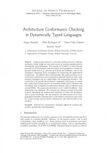
is based on kiltera as described in Chapter 2. The approach consists of the following four steps: 1. Construction of the high-level model (HLM) of the system, 2. Translation of the HLM into a kiltera model (KM), 3. Instrumentation of the implementation under test (IUT) and KM using the HLM, and 4. Execution of the instrumented IUT and the instrumented KM in parallel. Figure 3.1 shows the steps of our approach assuming the IUT is implemented using Aglets. We will now describe each of these steps in detail.
Figure 3.1: Steps of our conformance testing approach
CHAPTER 3. DESCRIPTION OF APPROACH
3.1.1
34
Construction of HLM
Application of the approach starts with the creation of a high-level model (HLM) of the system using, e.g., a UML profile. The HLM is assumed to capture the most relevant aspects of the system behavior such as descriptions of the movement of agents, their interaction with hosts and other agents, and any results computed. In order to describe mobile agent systems we use a UML profile introduced in [47] as our high-level modelling language. This profile extends the UML with four new types of Sequence Diagrams. Here we use only one of these types, called “Swimlaned Mobility Diagrams” (SMDs for short). These diagrams are intended to represent agent location, agent creation and agent movement. Note that UML2 sequence diagrams and therefore also SMDs support the standard control flow constructs such as branching, loops, and parallel and sequential composition. For instance, Figure 3.2 on page 34 shows how to specify a request from X to Y and to check whether the result that X got from Y is equal to “ok” or not. If yes, then X will do A, otherwise, do B. An SMD
Figure 3.2: A conditional interaction in standard Sequence Diagrams
consists of one or more swimlanes representing nodes (a.k.a. hosts or locations). Each
CHAPTER 3. DESCRIPTION OF APPROACH
35
swimlane is visually represented by a column labelled with the name of the node. Within each swimlane there is a Sequence Diagram with a life-line for each agent in that node. In addition to the standard message arrows for Sequence Diagrams, SMDs can have two new types of arrows between agent life-lines: 1) arrows that represent agent creation, labelled new, and 2) arrows that represent agent movement between nodes, labelled move. Message arrows between life-lines in different swimlanes represent remote communication. Figure 3.3 on page 35 shows a small example where an agent P1 located at a node A creates, in the same node, a new agent P2 which subsequently migrates to a node B.
Figure 3.3: A simple Swimlaned Mobility Diagram (SMD)
3.1.2
Construction of KM from HLM
In the second step of our approach, the HLMs are translated into kiltera models (KMs). In this step, the translation from HLM to KM is assumed to be manual, but since kiltera is Turing complete, i.e., every computable algorithm can be expressed in kiltera, this translation is guaranteed to always be possible. Moreover, kiltera offers direct support
CHAPTER 3. DESCRIPTION OF APPROACH
36
for many relevant features (e.g., support for concurrency with (a)synchronous message passing, movement of processes, time, and site-dependent behaviour). Consequently, expressing these concepts in KM is quite straightforward. Partial automation of this translation is possible. However, it is outside the scope of this thesis. Now we sketch how to go from high-level models specified as SMDs to executable models specified as kiltera models. First we discuss briefly how standard Sequence Diagrams can be represented in kiltera. Then we describe how SMDs are represented. Emulating standard Sequence Diagrams in kiltera In a normal Sequence Diagram we have several life-lines for different active objects. Arrows between life-lines represent message passing. In kiltera, active objects are processes: a process definition corresponds to the class of an active object and object creation is achieved by process instantiation. The ports in a process definition determine the messages that a process can send or receive. The parallel composition operator par is used to spawn parallel life-lines. Message-passing is achieved with trigger (to send a message) and when to wait for a message. Communication in kiltera is asynchronous. Synchronous messages can be modeled by means of an acknowledgment/response protocol. This is typically done as follows: the sender of a message creates a local “response” channel and sends this channel together with the message, and then waits for the answer on this new local channel. The receiver uses this private channel to send an acknowledgment, or the response to the message. Figure 3.4 shows such an example.
CHAPTER 3. DESCRIPTION OF APPROACH
37
1 process
Sen der [ x c h ] : channel r e s p o n s e c h in seq t r i g g e r x c h with ( ‘ ‘ message ’ ’ , r e s p o n s e c h ) when r e s p o n s e c h with r e s u l t −> // Do s o m e t h i n g w i t h r e s u l t
2 3 4 5 6 7
8 process
Receiver [ x ch ] : when x c h with ( data , r e s p o n s e c h ) −> // Do s o m e t h i n g w i t h d a t a t r i g g e r r e s p o n s e c h with answer
9 10 11 12 13 in 14 15 16 17
channel a c h in par Sender [ a c h ] Receiver [ a ch ]
Figure 3.4: Message communication in kiltera Emulating SMDs in kiltera In kiltera, sites play the role of nodes or hosts. Within a kiltera model, sites have symbolic names, introduced by the sites keyword. These symbolic names can be associated with actual IP addresses in a separate configuration file. Agents are represented by modules. Before an agent is able to create agents in a remote site or move to a remote site, it needs to know the target site. There are three ways in which an agent can know a site. The first is if the site was given in its sites declaration. The second is by using the here operator to obtain the name of the local site. The third is by receiving a site name sent by another agent. This is possible since site names are considered first-class values and therefore they can be transmitted in messages through channels. Modeling the creation and movement of agents can be done in several ways, and it depends on how we assign the responsibility of moving agents, that is, who initiates movement: should an agent tell another agent to move, or should an agent move itself.
CHAPTER 3. DESCRIPTION OF APPROACH
38
Also, there are different approaches to transferring the state of an agent. Furthermore, we can create an agent first locally and then move it, or we can create it at the remote site. The latter is directly captured by the semantics of the move construct: move A[˜ x](˜ y ) to s creates a new instance of A in a (possibly remote) site s, linked through the channels x˜ and with initial state values given by y˜. Creating a copy of an agent (module) locally can be achieved by here s in move A[˜ x](˜ y ) to s. This shows how new arrows of SMDs can be directly modeled with the move operator. So in this case, the process/module creating the agent is also responsible for moving the agent to the target site. How can we emulate an agent migrating on its own? The simplest way is by capturing all the necessary state, test if the agent is already in the destination, and if not, move a copy of itself there with the required initialization state and stop. For example, the HLM presented in Figure 3.3 on page 35 could be encoded in kiltera as in Figure 3.5.
1 2 3 4 5 6 7 8 9
module P2 [ x c h ] ( s t a t e ) : s i t e s A, B // Use modify s t a t e y i e l d i n g n e w s t a t e here s in match s with A −> move P2 [ x c h ] ( n e w s t a t e ) to B | B −> // . . . do what n e e d s t o be done i n B
Figure 3.5: The kiltera model of the corresponding SMD presented in Fig. 3.3
CHAPTER 3. DESCRIPTION OF APPROACH
3.1.3
39
Instrumentation of IUT and KM using HLM
After we have constructed the HLMs and translated them into KMs, we start the instrumentation step. In the instrumentation step, we instrument both the IUT (implemented in Aglets) and the KM to allow relevant information to flow from the IUT to the KM. We instrument the IUT first because it is going to send information to the KM. We use the HLM to start the instrumentation step. First, we identify a collection of “check points” at which conformance between the (IUT) and the KM is to be checked. Typically, check points involve the sending or receipt of messages or agent movement. Figure 3.6 shows the HLM with a check point numbered by 1 inserted before the agent P2 moves from node A to node B.
Figure 3.6: SMD with a check point Then we manually locate these check points in the IUT and the KM. Figure 3.7 shows the location of the check point 1 in the IUT (move the agent from node A to node B) and Figure 3.8 shows the corresponding location of check point 1 in KM. Next, at each check point in the IUT, we insert appropriate instrumentation code which transmits relevant state information to the KM via sockets through a process
CHAPTER 3. DESCRIPTION OF APPROACH
1 2 3 4 5
40
public void onArrival ( MobilityEvent me) { /∗ Check P o i n t 1 ∗/ /∗ Agent a r r i v e d a t a new d e s t i n a t i o n ∗/ ... }
Figure 3.7: Location of check point 1 in the IUT of agent P2 1 2
// Check p o i n t 1 move P2 [ x c h ] ( n e w s t a t e ) to B
Figure 3.8: Location of check point 1 in the KM of agent P2 we call “Python connector”. The Python connector is a Python script [1] that serves as a “bridge” between the IUT with the KM. In addition, at each check point in the KM, we insert instrumentation code that receives state information from the IUT and compares it with the expected internal information; if they are different, then nonconformance is signalled; otherwise, the KM continues. Figure 3.9 and Figure 3.10 show examples of instrumentation code inserted in the IUT and in the KM respectively.
1 2 3 4 5 6 7 8 9 10 11 12
public void onArrival ( MobilityEvent me) { try { /∗ Check p o i n t 1 ∗/ /∗ I n s e r t e d code b e g i n ∗/ S o c k e t s = new S o c k e t ( ‘ ‘ l o c a l h o s t ’ ’ , 6 0 0 0 2 ) ; P r i n t S t r e a m s t r = new P r i n t S t r e a m ( s . getOutputStream ( ) ) ; s t r . p r i n t l n ( ‘ ‘ Agent P2 t r a v e l e d t o node B ’ ’ ) ; /∗ i n s e r t e d code end ∗/ /∗ Agent a r r i v e d a t a new d e s t i n a t i o n ∗/ } ... }
Figure 3.9: Code inserted into the IUT of agent P2 at check point 1 The instrumentation in Figure 3.9 causes the name of the process and the destination to be sent in a string via socket s just when the process arrived at the new destination.
CHAPTER 3. DESCRIPTION OF APPROACH
1 2 3 4 5 6 7 8 9
41
// Check p o i n t 1 // I n s e r t e d code b e g i n HandleJavaMessages [ e x t e r n a l c h ] when e x t e r n a l c h with data−> i f data = ‘ ‘ Agent P2 t r a v e l e d to node B’ ’ then move P2 [ x c h ] ( n e w s t a t e ) to B . else // Error , s t o p e x e c u t i o n w i t h non−conformance // i n s e r t e d code end
Figure 3.10: Code inserted into KM of agent P2 at check point 1 The kiltera code in Figure 3.10 receives a string from the Python connector via channel external_ch. If the string has the expected content, the process moves.
3.1.4
Execution of IUT and KM
During the last step of our approach we execute the instrumented IUT and the instrumented KM, both possibly in a distributed fashion, and check the conformance between them. While the IUT is running, it sends messages possibly including state information to the KM through the Python connector. When the KM receives a message from IUT through the Python connector, it compares it with its expected internal state. In the case of non-conformance, the KM stops its execution and outputs an error message together with the trace of the execution. Figure 3.11 shows the architecture of the monitoring infrastructure of our approach.
3.2
Chapter Summary
Relatively little work has been done to support quality assurance techniques such as testing and verification of mobile agent systems [26, 89]. In this chapter we have presented a new approach for runtime conformance checking of mobile agent systems
CHAPTER 3. DESCRIPTION OF APPROACH
42
Figure 3.11: The architecture of the monitoring infrastructure
using executable model. Our approach combines support for mobility, distributed execution and time and uses models which can be directly executed in a distributed simulation environment. The kiltera modeling language is an extension of the well known π-calculus and rests on a firm theoretical foundation which includes a formal semantics and different notions of equivalence [71]. The model specifies the agent system behaviour in high-level operational, rather than declarative, terms (e.g., through the use of a specification logic such as Linear Temporal Logic as in Java MaC [45, 44]) which we feel is more suitable for the description of possibly complex agent interactions. Our approach only assumes the availability of the socket communication in the agent platform. On the downside, the kiltera model currently needs to be created manually. Moreover, our notion of conformance is not currently formally defined, but it is inspired by simulation relations defined for most process algebras such as CCS
CHAPTER 3. DESCRIPTION OF APPROACH
and the π-calculus.
43
Chapter 4 Case Studies In this chapter we demonstrate the effectiveness of our proposed approach described in Chapter 3 by using four case studies. Two of them are mobile agent systems, the two others are implementations of distributed algorithms. The first example is an online shopping agent application implemented by the author using Aglets. In this application, an agent is searching for a specific item (e.g., a camera) by traveling to different online shopping malls in order to find the lowest price for this item and return the result of the search to the original site. The second example presents a scenario where different partners, who are spatially separated from each other, want to sign a contract for a specific project. To this end, an agent representing the contract migrates to all the partners involved. The two other examples are implementations of a token ring mutex algorithm and Lamport’s distributed mutex algorithm (implementations of these two algorithms are taken from [35]). We checked several properties of these examples including the correct movement of mobile agents as well as the proper realization of behavioral and timing constraints. In Section 4.1, we apply the four steps of our approach to the online shopping example. 44
CHAPTER 4. CASE STUDIES
45
Section 4.2 discusses the application of our approach to the second example. Section 4.3 discuses its use for the analysis of two distributed algorithms. Finally, Section 4.4 summarizes the chapter.
4.1
Case Study: Online Shopping Example
In this experiment we have applied the four steps of our conformance checking approach to the online shopping example. This section shows some examples of checking sample properties of the shopping application.
4.1.1
General Description
In this application, an agent is searching for a specific item (e.g., a camera) by traveling to different online shopping malls in order to find the lowest price for this item and return the result of the search to the original site. To facilitate the presentation, we consider a system with two malls which have two shops and one shop respectively. Note that the evaluation in Chapter 6 will be carried out an a larger system.
4.1.2
Application of our Approach
Step 1: Construction of the HLM Our approach starts with describing the desired behavior of the system using SMDs described in Chapter 3. Figure 4.1 on page 46 shows the SMD of a scenario in the shopping application. We begin by setting up the scenario, creating two Malls and a client. The first one is Mall1 created at Mall1site with two shops (Shop1 and Shop2) and the second mall is Mall2 created at Mall2site that has one shop (Shop3). The
CHAPTER 4. CASE STUDIES
46
client creates an agent that is responsible for finding the lowest price. In this scenario, the agent is sent to Mall1 and then it goes to Mall2. In each mall, the agent queries the mall’s information kiosk for a list of shops in the mall. Then, it asks each shop for the price of the camera and updates the current best price, if necessary. After the agent has finished visiting all malls, it sends the best price and the corresponding shop back to the client.
Figure 4.1: The SMD of overall online shopping system In order to clarify the model further, we divide the HLM presented in Figure 4.1 into HLMs for the client, agent, malls and the “main” (i.e., a component that sets up
CHAPTER 4. CASE STUDIES
47
the entire scenario). We will only show the HLMs for the main, the client, and the agent. The HLM for the main is shown in Figure 4.2 on page 47. The initialization consists of three steps: creating the client, creating the malls by specifying their sites (in this example we have two malls: Mall1 and Mall2 created in sites Mall1site and Mall2site respectively) with different shops and by providing the addresses of these malls to the client to start the search process.
Figure 4.2: The SMD of the initialization process
Once the client gets a mall list from the main, it creates an agent at Mall1site, provides it with the addresses of the other malls, and waits for the result to be returned from the agent. The agent waits for a specific amount of time to get a response from a shop. Figure 4.3 on page 48 shows the HLM of the client. After the agent has been created at Mall1site, it sends a message to the Mall1 asking it for the shop list (i.e., the list of shops in this mall). After that, it starts sending messages to the shops one by one and in a specific order asking and waiting for their prices of the camera. The agent has a specific amount of time to get a result from the shop whether it has the product camera or not. If that amount of time is elapsed the agent moves to the next shop. Then, the agent moves to the second mall
CHAPTER 4. CASE STUDIES
48
Figure 4.3: The SMD of the client
located at Mall2site and does the same thing. Once the agent has queried all shops and visited all malls, it sends a message to the client telling him the minimum price and in which shop and mall the cheapest camera can be found. Figure 4.4 shows the HLM of the agent. Appendix A shows all the HLMs of the online shopping example. Step 2: Construction of KM from HLM In the second step of our approach, the HLMs are translated into kiltera models (KMs); kiltera’s direct support for many relevant features (e.g., support for concurrency with (a)synchronous message passing, movement of processes, time, and site-dependent behavior) makes this translation relatively straight-forward. Figure 4.5 on page 50 shows the Main KM of the corresponding HLM presented in Figure 4.2 on page 47. The three sites are declared in line 2 and the channels to the client and the malls’s information kiosk are introduced in line 3. The statements in lines 5-8 are executed in parallel: create an instance of Client with one channel (to_cust) at site Home (line 5), create an instance of Mall1 with channel mall1_info at site Mall1site (line 6), create an instance of Mall2 with channel mall2_info at site Mall2site (line 7), and send the
CHAPTER 4. CASE STUDIES
49
Figure 4.4: The SMD of the agent
mall sites and their channels to the client through the channel to_cust (line 8). Figure 4.6 on page 50 shows the Client KM of the corresponding HLM presented in Figure 4.3 on page 48. In this figure, after the Client has received all mall addresses (line 2), it starts its process by creating the Agent at site mallsite (line 5). The Agent is connected to channels from_agent (to send back the result) and mall_info (the link to the information desk where the Agent is located). Variable mallsite is bound to the first mall in the list of malls received from Main. Furthermore, the client sends the agent the remaining mall addresses rest (line 2). Then, the Client waits for the result from the Agent (line 6). The result is the price, and a link to the
CHAPTER 4. CASE STUDIES
50
1 module
Main : s i t e s Home , M a l l 1 s i t e , M a l l 2 s i t e in 3 dchannel t o c u s t , m a l l 1 i n f o , m a l l 2 i n f o in 4 par 5 move C l i e n t [ t o c u s t ] to Home 6 move Mall1 [ m a l l 1 i n f o ] to M a l l 1 s i t e 7 move Mall2 [ m a l l 2 i n f o ] to M a l l 2 s i t e 8 t r i g g e r t o c u s t with [ ( M a l l 1 s i t e , m a l l 1 i n f o ) , ( M a l l 2 s i t e , m a l l 2 i n f o ) ] . 2
Figure 4.5: The KM of the initialization process of the shopping example shop where the agent found the minimum price of the camera. 1 module
C l i e n t [ from main ] : from main with [ ( m a l l s i t e dchannel f r o m a g e n t in par move Agent [ f r o m a g e n t , m a l l when f r o m a g e n t with ( p r i c e // p r i n t where t h e Agent
2 when 3 4 5 6 7
, m a l l i n f o ) ; r e s t ] −>
i n f o ] ( r e s t , n u l l , n u l l ) to m a l l s i t e , s h o p c h ) −> found t h e min p r i c e
Figure 4.6: The KM of the client Figure 4.7 on page 51 shows the agent KM of the corresponding HLM presented in Figure 4.4 on page 49. The Agent consists of four subprocesses: GetShopList, QueryShops, EnterShop and GoToNextMall. When an agent arrives at a mall it executes the process GetShopList (line 38). This process sends a message to the mall information booth asking for the shop list. When it receives the shop list (line 6), it starts querying the shops (invoking process QueryShops in line 7) one by one searching for the camera and updating the current lowest price if necessary. This is done by invoking EnterShop (lines 19-29) which asks the shop if it has the camera or not; if this is the case and the shop sends a price less than the bestprice that we have so far, then the new best price is updated (line 25); otherwise, the bestprice is left unchanged (line 27). If the Agent did not get a response from the shop within some time t (the time the agent is allowed to stay in each shop), then the Agent continues with the next shop. After the Agent exits a shop it invokes recursively QueryShops
CHAPTER 4. CASE STUDIES
1 module
Agent [ t o c u s t o m e r , t o m a l l ] ( m a l l l i s t , b e s t p r i c e , b e s t s h o p ) : Ge t Sh opL i s t [ m a l l i n f o ] : channel r e s p o n s e c h in par t r i g g e r m a l l i n f o with ( ‘ ‘ g e t shop l i s t ’ ’ , r e s p o n s e c h ) when r e s p o n s e c h with s h o p l i s t −> QueryShops [ s h o p l i s t ] ( b e s t p r i c e , b e s t s h o p )
2 process 3 4 5 6 7 8 9 process 10 11 12 13 14 15 16 17
QueryShops [ s h o p l i s t ] ( b e s t p r i c e h e r e , b e s t s h o p h e r e ) : match s h o p l i s t with [ ] −> GoToNextMall [ ] ( b e s t p r i c e h e r e , b e s t s h o p h e r e ) | [ s h o p c h ; r e s t ] −> event s h o p v i s i t e d in EnterShop [ shop ch , s h o p v i s i t e d ] ( b e s t p r i c e h e r e , b e s t s h o p h e r e ) when s h o p v i s i t e d with ( n e w b e s t p r i c e , n e w b e s t s h o p ) −> QueryShops [ r e s t ] ( n e w b e s t p r i c e , b e s t s h o p )
18 19 process 20 21 22 23 24 25 26 27 28 29
EnterShop [ shop ch , s h o p v i s i t e d ] ( b e s t p r i c e , b e s t s h o p h e r e ) : channel r e s p o n s e c h in par t r i g g e r s h o p c h with ( ‘ ‘ camera ’ ’ , r e s p o n s e c h ) when r e s p o n s e c h with p r i c e −> i f p r i c e < b e s t p r i c e then t r i g g e r s h o p v i s i t e d with ( p r i c e , s h o p c h ) else t r i g g e r s h o p v i s i t e d with ( b e s t p r i c e , b e s t s h o p h e r e ) timeout t −> t r i g g e r s h o p v i s i t e d with ( b e s t p r i c e , b e s t s h o p h e r e )
30 31 process 32 33 34 35 36
GoToNextMall [ ] ( b e s t p r i c e , b e s t s h o p ) : match m a l l l i s t with [ ] −> t r i g g e r t o c u s t o m e r with ( b e s t p r i c e , b e s t s h o p ) | [ ( m a l l s i t e , m a l l i n f o ) ; r e s t ] −> move Agent [ t o c u s t o m e r , m a l l i n f o ] ( r e s t , b e s t p r i c e , b e s t s h o p ) to m a l l s i t e
37 in 38
Ge t Sh o pL i s t [ t o m a l l ]
Figure 4.7: The Agent KM
51
CHAPTER 4. CASE STUDIES
52
(line 17) with the remainder of the shop list. Once the Agent has finished the shop list (which means the shop list is empty in line 11), then it executes the GoToNextMall process which checks whether there are more malls to visit or not. If there are more malls (line 35), the Agent travels to the next mall by creating an instance of Agent at that mall with an updated state (line 36) and behaves in the same way. If the Agent has visited all malls (malllist is empty, line 33), it sends the result back to the Client telling him the lowest price and where the cheapest camera was found (line 34). As we can see from example in Figure 4.7 on page 51, the move statement sends an instance of the process Agent in the remote site mallsite and any state information is provided as parameters to the Agent. Furthermore, while the Agent is trying to find the best price of the product camera, it uses a timeout in the shop because if the shop does not respond (e.g., because it is down), then the Agent should not wait forever. Appendix A shows all the KMs of the online shopping example. Step 3: Instrumentation of IUT and KM using HLM After we have constructed the HLMs and translated them into KMs of the shopping example, we start the instrumentation step. Before we talk about the instrumentation we have to mention here that we use the Aglets platform [49, 3] in order to implement the online shopping application illustrated in Figure 4.1 on page 46. In the instrumentation step, we instrument both the IUT (implemented in Aglets) and the KM to allow relevant information to flow from the IUT to the KM. We instrument the IUT first because it is going to send information to the KM. We use the HLM presented in Section 4.1.2 to start the instrumentation step. First we identify
CHAPTER 4. CASE STUDIES
53
a collection of “check points” at which conformance between the (IUT) and the KM is to be checked. Typically, check points involve the sending or receipt of messages or agent movement. The number and locations of checkpoints are determined by the constraints to be enforced. More precisely, the users must ensure that the information required for enforcing the constraints is communicated to the KM at the appropriate time. Figure 4.8 shows the HLM with 5 check points numbered from 1 to 5 presented as a circle.
Figure 4.8: Check points locations in camera searcher scenario SMD
Once we have decided on the checkpoints in the HLM we locate them in the IUT and the KM. Figure 4.9 on page 54 shows the location of check point 5 in the IUT
CHAPTER 4. CASE STUDIES
54
(the agent moved to a mall site) and Figure 4.10 on page 54 shows the corresponding location of check point 5 in the KM. 1 public 2 /∗ 3
void onArrival ( MobilityEvent me) { Check p o i n t 5 ∗/
...
4}
Figure 4.9: Location of check point 5 in the IUT
1 2
// Check p o i n t 5 move Agent [ t o c u s t o m e r , m a l l i n f o ] ( r e s t , b e s t p r i c e , b e s t s h o p ) to m a l l s i t e
Figure 4.10: Location of check point 5 in the KM Next, at each check point in the IUT, we insert appropriate instrumentation code which transmits relevant state information to the KM via sockets through the Python connector. In addition, at each check point in KM, we insert instrumentation code that receives state information from the IUT and compares it with the expected internal information; if they are different, then non-conformance is signalled; otherwise, the KM continues. The comparison may require the addition of a specific routine that implements the constraint that is to be enforced at that checkpoint. Constraints may restrict individual messages or entire sequences of messages. For instance, suppose each shop in a mall is to be queried exactly once. The instrumentation needs to ensure that the IUT sends the name of the shop about to be queried to the KM while the KM keeps track of the shops queried so far. Figure 4.11 and Figure 4.12 show the instrumentation code inserted in IUT and in KM respectively.
CHAPTER 4. CASE STUDIES
1 public
55
void onArrival ( MobilityEvent me) {
2 try { 3 /∗
Check p o i n t 5 ∗/ I n s e r t e d code b e g i n ∗/ 5 S o c k e t s = new S o c k e t ( ‘ ‘ l o c a l h o s t ’ ’ , 6 0 0 0 2 ) ; 6 P r i n t S t r e a m P = new P r i n t S t r e a m ( s . getOutputStream ( ) ) ; 7 P . p r i n t l n ( ‘ ‘ Agent t r a v e l e d t o n e x t mall ’ ’ ) ; 8 /∗ i n s e r t e d code end ∗/ 9} 10 . . . 11 } 4 /∗
Figure 4.11: Code inserted into IUT at check point 5 1 // Check
point 5 code b e g i n 3 HandleJavaMessages [ e x t e r n a l c h ] 4 when e x t e r n a l c h with data−> 5 i f data = ‘ ‘ Agent t r a v e l e d to n e x t mall ’ ’ then 6 move Agent [ t o c u s t o m e r , m a l l i n f o ] ( r e s t , b e s t p r i c e , b e s t s h o p ) to m a l l s i t e . 7 else 8 // Error , s t o p e x e c u t i o n w i t h non−conformance 9 // i n s e r t e d code end 2 // I n s e r t e d
Figure 4.12: Code inserted into KM at check point 5 Step 4: Execution of IUT and KM In the last step of our approach we execute the instrumented shopping example and the instrumented KM and check the conformance between them. The following Subsection 4.1.3 lists examples of some relevant properties and some observations are presented in Section 4.1.4. A full evaluation of the approach to determine its ability to detect faults in the implementation of the online shopping example will be given in Chapter 6.
4.1.3
Checking sample properties
To implement a particular conformance check in the KM, it is important that all necessary information is sent from the IUT. For instance, to check that an agent in
CHAPTER 4. CASE STUDIES
56
the IUT has moved properly to a new node it suffices for the IUT to send a string to the KM describing the target of the movement. However, to check more complex behavioral constraints (e.g., that a sequence of actions has been performed in the right order), the KM may have to maintain and query additional state information. Finally, to check that timing constraints have been met, timing information needs to be communicated and timeouts may have to be used. Examples for each of these kinds of conformance checks are given below. Property 1: Agent visits next mall at expected time At the checkpoint shown in Figure 4.12 on page 55, the KM expects a message from the IUT containing the string "Agent traveled to next mall" (lines 3-5). If such a string is received, the KM continues its execution by creating an instance of Agent and moves it to the next mall site mall_site (lines 6-7). If any other kind of message is received (because, for instance, the number of malls or the number of shops in a mall in the IUT and the KM do not match, or the IUT did not query all shops in a mall) the behavior of the IUT is non-conformant (line 9). In that case, the KM outputs an error message and terminates. Property 2: Agent queries each shop in a mall exactly once Suppose each shop in a mall is to be queried exactly once. The instrumentation needs to ensure that the IUT sends the name of the shop about to be queried to the KM, while the KM keeps track of the shops queried so far. In Figure 4.13 on page 57, after receiving a message in line 14, the KM checks whether the IUT has already queried this shop or not by checking the list Jshoplist (using the process Search in line 17). If
CHAPTER 4. CASE STUDIES
57
the shop name received from the IUT (Jshopname) is already contained in Jshoplist (Search sends a message ‘‘Found’’ to the listener in line 18), non-conformance is signalled (line 20); otherwise, the shop is added to Jshoplist (line 22) and execution continues. 1 process 2 3 4 5 6 7 8 9
S e a r c h [ a n s w e r c h ] ( l i s t , item ) : match l i s t with [ ]−> t r i g g e r a n s w e r c h with ‘ ‘ Not Found ’ ’ . | [ hd ; r e s t ]−> i f hd = item then t r i g g e r a n s w e r c h with ‘ ‘ Found ’ ’ . else S e a r c h [ a n s w e r c h ] ( r e s t , item )
10 11 process 12 13 14 15 16 17 18 19 20 21 22 23 24
loop [ S h o p l i s t ] ( Jshoplist , . . . ) ... HandleJavaMessages [ e x t e r n a l c h ] when e x t e r n a l c h with Jshopname−> event c h e c k i t e m in par S e a r c h [ c h e c k i t e m ] ( J s h o p l i s t , Jshopname ) when c h e c k i t e m with data−> i f data = ‘ ‘ Found ’ ’ then // Error shop v i s i t e d t w i c e else l e t J s h o p l i s t = enqueue ( J s h o p l i s t , Jshopname ) in ...
Figure 4.13: Checking Property 2 in KM
Property 3: Timing constraints Figure 4.14 on page 58 shows the KM that is used to check time conformance. More precisely, we check that shops respond to queries in a timely fashion (within t seconds) and that the agent reacts appropriately to delayed shop responses. The instrumentation needs to ensure that the agent in the IUT informs the KM how long it had to wait in response to a query. The agent in the KM will receive this time in responsetime in line 5. If responsetime is greater than t (line 6), non-conformance is reported.
CHAPTER 4. CASE STUDIES
58
Also, if the KM agent does not receive a response from the shop in the KM within t seconds (line 13), but a proper response has been received from the shop in the IUT (line 20), we have non-conformance. t r i g g e r s h o p c h with ( ‘ ‘ camera ’ ’ , r e s p o n s e c h ) . r e s p o n s e c h with ( s h o p p r i c e , . . . ) −> 3 par 4 HandleJavaMessages [ e x t e r n a l c h ] 5 when e x t e r n a l c h with r s p o n s e t i m e−> 6 i f ( f l o a t ( r s p o n s e t i m e ) 14 par 15 HandleJavaMessages [ e x t e r n a l c h ] 16 when e x t e r n a l c h with data−> 17 i f ( data = ‘ ‘ Not Found ’ ’ ) o r ( data = ‘ ‘No Respond ’ ’ ) then 18 t r i g g e r n e x t c h with ( ‘ ‘ Get Next Shop ’ ’ , . . . ) . 19 else 20 //non−conformance , IUT f i n d t h e camera b u t KM d i d n o t 1
2 when
Figure 4.14: Checking Property 3 in KM
4.1.4
Observations
Table 4.1 compares the size of the IUT and the KM before and after the instrumentation. Table 4.1: Size in lines of code of the IUT and KM before and after the instrumentation IUT
File Name
Main Client Agent Mall1 with 3 shops Mall2 with 2 shops
KM
Before Inst.
After Inst.
Before Inst.
After Inst.
26 57 212 186 131
26 82 262 186 131
8 8 38 23 21
8 20 151 23 21
CHAPTER 4. CASE STUDIES
59
We make the following observations: 1. The instrumentation increases the size of the agent the most. This is because the agent carries out most of the behavior and contains the most check points. Instrumentation to the other files is much smaller. Neither the Main nor any of the malls require any instrumentation. 2. Both, before and after the instrumentation, the size of the kiltera code is considerably smaller than that of the corresponding Aglets code. We view this as an indication that kiltera does indeed allow a succinct expression of mobile and distributed computation. The approach allowed us to find seeded faults in the implementation. A more evaluation of the ability of the approach to detect faults will be given in Chapter 6.
4.2 4.2.1
Case Study: Contract Signing General Description
The description of this example has been taken from [13]. In this example, several distributed partners want to sign a contract for a specific project. A coordinator called notary guides the process of signing the contract by all partners. The notary first creates the partners and the contract. After that, the notary is responsible for sending the addresses of the partners to the contract. Moreover, it is responsible for assigning the partners to the contract for signing it. There is only one contract to avoid inconsistency. The partners can view and sign the contract. Moreover, each partner has a specific amount of time to sign the contract. If the time has elapsed,
CHAPTER 4. CASE STUDIES
60
the notary moves the contract to the next partner. The contract is always moved by the notary via a remote reference from one partner to the other in order to be signed. Finally, the notary should check whether all the partners have signed the contract or not. A partner can only sign the contract when they are at same place. In this example, we will consider a system with two partners just to make it simple.
4.2.2
Application of our Approach
Step 1: Construction of the HLM We start our approach by describing the SMD of the contract signing example. Figure 4.15 shows the SMD scenario of signing a contract.
The scenario starts
when the Notary creates the Contract and the two partners. The contract is created at Home site (the same place of Notary) and Partner1, Partner2 are created at Partner1Site, Partner2Site respectively. In the scenario, the Notary asks Partner1 to sign the Contract. Since Partner1 does not have the contract, Partner1 replied “ I do not have it”. So the Notary asks the Contract to move to Partner1Site. After that, Partner1 signs the contract. Then, the Contract updates his list that contains the partners who signed the contract. The Notary then does the same thing with Partner2. Once the Contract visits all the partners, it goes back to the Notary. The Notary asks the Contract to check whether all the partners have signed the contract or not. If the result is yes, then Notary will print “All partners have signed the contract”. Otherwise, “not Ok” will be printed. We have divided the HLM presented in Figure 4.15 on page 61 into HLMs for the notary, the contract and the partners in order to clarify the model. We will show the HLMs for the notary, contract, and one partner. The HLM of the notary is
CHAPTER 4. CASE STUDIES
61
Figure 4.15: The SMD of the overall contract signing example shown in Figure 4.16. The notary is responsible for creating the contract and the two partners. Moreover, it is responsible for providing the addresses of these partners to the contract. After that, the notary sends a message to Partner1 to sign the contract. Since the contract is still at site Home and Partner1 at site Partner1Site, Partner1 cannot sign the contract and so he sends a reply message to the notary telling him that he does not have the contract to sign it. Once the Notary receives this message, he asks the Contract to move to the site of Partner1. After that, the notary sends a message to Partner2 asking him to sign the contract. And because the contract
CHAPTER 4. CASE STUDIES
62
Figure 4.16: The SMD of the notary is still at site Partner1Site he asks the contract to move to the site of Partner2. Once the Contract visits all the partners, the Notary asks the Contract to go back to the Home site. Once the Contract arrives at the Home site, the Notary sends a message to the Contract in order to check whether all partners have the signed the contract or not. If yes, the Notary prints “All partners signed”. Otherwise, it prints “not Ok”. The Contract moves from one site to another in order to be signed. Moreover, it updates the list of partners who signed the contract and checks whether all partners have signed the contract or not when it received a check request from Notary.
CHAPTER 4. CASE STUDIES
63
Figure 4.17 shows the SMD of the contract.
Figure 4.17: The SMD of the contract The partner is responsible for signing the contract once they are located at the same site. Figure 4.18 shows the SMD of Partner1. Step 2: Construction of KM from HLM The HLMs are translated into kiltera models (KMs). Figure 4.19 on page 65 shows the Notary KM of the corresponding HLM presented in Figure 4.16 on page 62. The Notary module identified that has one port notary_ch used to communicates with the contract and the partners (line 1). Moreover, other channels are introduced in line 4. The three sites are declared in line 2. Line 6 used to create an instance of Partner1 at Partner1Site with three channels: to_partner1 used to send messages from the Notary to Partner1, from_P1_to_Cont used for the communication between
CHAPTER 4. CASE STUDIES
64
Figure 4.18: The SMD of the Partner1 Partner1 and the Contract and the third channel to_notary used to send messages from the Partner1 to the Notary. Line 7 used to create an instance of Partner2 with three channels: to_partner2, from_P2_to_Cont and to_notary. These channels used to communicate with the Partner2, Contract and Notary with the same functionality as used in Partner1. Line 8 creates an instance of Contract with one channel (notary_ch) used to send messages from the Notary to the Contract. After creating all these instances, the Notary sends the addresses of all partners to the contract using the channel notary_ch (lines 10-12). The Notary then sends a message to Partner1 to sign the contract (line 14). At the same time the Notary starts waiting for a reply from Partner1 (line 15) or waiting for the t seconds to elapse in order to ask Partner2 to sign the contract (line 19). If Partner1 does not have the contract to sign it, the Notary will receive a message from Partner1 that he does not signed
CHAPTER 4. CASE STUDIES
65
1 module
Notary [ n o t a r y c h ] : s i t e s Home , P a r t n e r 1 S i t e , P a r t n e r 2 S i t e 3 process I n i t i a l [ ] : 4 dchannel t o p a r t n e r 1 , t o p a r t n e r 2 , f r o m P 1 t o C o n t , f r o m P 2 t o C o n t in 5 par 6 move P a r t n e r 1 [ t o p a r t n e r 1 , f r o m P 1 t o C o n t , n o t a r y c h ] to P a r t n e r 1 S i t e 7 move P a r t n e r 2 [ t o p a r t n e r 2 , f r o m P 2 t o C o n t , n o t a r y c h ] to P a r t n e r 2 S i t e 8 move C o n t r a c t [ n o t a r y c h ] to Home 9 seq 10 t r i g g e r n o t a r y c h with ( ‘ ‘ p a r t n e r s a d d r e s s e s ’ ’ , [ ] , 11 [ Partner1Site , from P1 to Cont , ‘ ‘ Partner1 ’ ’ ) , 12 ( Partner2Site , from P2 to Cont , ‘ ‘ Partner2 ’ ’ ) ] ) . 13 par 14 trigger t o p a r t n e r 1 with ( ‘ ‘ S i g n Contract ’ ’ , ‘ ‘ Home ’ ’ ) . 15 when n o t a r y c h with ( ‘ ‘ P a r t n e r 1 not s i g n e d ’ ’ , r e s p o n s e c h )−> 16 par 17 t r i g g e r r e s p o n s e c h with ( ‘ ‘ S i g n Contract ’ ’ , ‘ ‘ P a r t n e r 1 S i t e ’ ’ ) . 18 move C o n t r a c t [ n o t a r y c h ] to P a r t n e r 1 S i t e 19 wait t −> 20 par 21 trigger t o p a r t n e r 2 with ( ‘ ‘ S i g n Contract ’ ’ , ‘ ‘ P a r t n e r 1 S i t e ’ ’ ) . 22 when n o t a r y c h with ( ‘ ‘ P a r t n e r 2 not s i g n e d ’ ’ , r e s p o n s e c h )−> 23 par 24 t r i g g e r r e s p o n s e c h with ( ‘ ‘ S i g n Contract ’ ’ , ‘ ‘ P a r t n e r 2 S i t e ’ ’ ) . 25 move C o n t r a c t [ n o t a r y c h ] to P a r t n e r 2 S i t e 26 wait 2∗ t−> 27 par 28 t r i g g e r n o t a r y c h with ( ‘ ‘ c h e c k l i s t ’ ’ , [ ‘ ‘ P a r t n e r 1 ’ ’ , ‘ ‘ P a r t n e r 2 ’ ’ ] ) . 29 move C o n t r a c t [ n o t a r y c h ] to Home 30 in 31 Initial [] 2
Figure 4.19: The KM of the notary the contract (line 15). The message also contains a channel response_ch used to send a reply from Notary to Partner1 asking him again to sign the contract (line 17) after the Notary moves the Contract to the Partner1Site (line 18). Partner1 has t seconds to sign the contract (line 19). If the time has elapsed, the Notary asks Partner2 to sign the Contract. Then the Notary does the same thing (as he did with Partner1) with Partner2 (lines 20-25). Again, Partner2 has also the same time as Partner1 to sign the contract. So the Notary waits another t seconds (t+t= 2*t) to let Partner2 to sign the contract (line 26). If the time (2*t) has elapsed, the Notary asks the Contract to go back to site Home (line 29) and asks the Contract to check whether all partners have signed the contract or not (line 28).
CHAPTER 4. CASE STUDIES
66
Figure 4.20 on page 66 shows the Contract KM of the corresponding HLM presented in Figure 4.17 on page 63. The Contract KM consists of two processes: 1 module
C o n t r a c t [ from No ] : f u n c t i o n Enqueue ( queue , item ) : 3 match queue with 4 [ ] −> 5 [ item ] 6 | [ hd ; t l ] −> 7 [ hd ; Enqueue ( t l , item ) ] 8 process H a v e A l l S i g n [ ] ( p a r t n e r s i g n e d ) : 9 when from No with ( ‘ ‘ c h e c k l i s t ’ ’ , l i s t )−> 10 i f l i s t = p a r t n e r s i g n e d then 11 print ‘ ‘ A l l p a r t n e r s a r e s i g n e d t h e c o n t r a c t ’ ’ . 12 else 13 print ‘ ‘ not Ok ’ ’ . 14 process S i g n [ ] ( p a r t n e r s i g n e d , p a r t n e r l i s t ) : 15 match p a r t n e r l i s t with 16 [ ] −> 17 HaveAllSign [ ] ( p a r t n e r s i g n e d ) 18 | [ ( p s i t e , p l i n k , pname ) ; r e m a i n d e r ] −> 19 when p l i n k with ( ‘ ‘ S i g n Contract ’ ’ , recpname )−> 20 i f pname = recpname then 21 l e t p a r t n e r s i g n e d = Enqueue ( p a r t n e r s i g n e d , recpname ) 22 in 23 par 24 print pname ˆ ‘ ‘ : i signed the contract ’ ’ . 25 Sign [ ] ( partnersigned , remainder ) 26 in 27 when from No with ( ‘ ‘ p a r t n e r s a d d r e s s e s ’ ’ , p a r t n e r s i g n e d , p a r t n e r l i s t ) −> 28 Sign [ ] ( partnersigned , p a r t n e r l i s t ) 2
Figure 4.20: The KM of the contract Sign and HaveAllSign. Moreover, it has one function Enqueue (lines 2-7) used to add the partners who have signed the contract to the list partnersigned. Process HaveAllSign (lines 8-13) used to check whether all partners are signed the contract or not by comparing the list which contains all partners with partnersigned list which contains all signed partners (line 10). If these two lists are equal, then statement at line 11 will be executed. Otherwise, statement at line 13 will be executed. The execution of the Contract starts when it receives the partners addresses from the Notary through the channel from_No (line 27). Once the Contract received these addresses, it starts listening to the partners for signing the contract (line 28). The
CHAPTER 4. CASE STUDIES
67
Sign process has two parameters, the list partnersigned, and the list partnerlist. The partnerlist is a list that contains the partners who have signed the Contract. More precisely, this list contains the partner site (psite), the channel used to connect a partner with the contract (plink) and the partner name for each partner (pname). If partnerlist is empty (line 16) it means that all partners had the chance to sign the contract, but it does not mean that all partners have signed the contract. But if partnerlist still have some partners to sign the contract, then the Contract waits for a request from the current partner in the list to sign it through the connection channel between them which is plink (line 19). Line 20 is used to make sure that the partner who makes the request to sign the contract is the same partner who is on the top of the list. The partner who signed the contract will be added to partnersigned (line 21) and the Contract prints a statement showing that the current partner has signed the Contract (line 24). Line 25 makes the Contract listen to the requests of other partners if they exist. Figure 4.21 on page 67 shows the Partner1 KM of the corresponding HLM presented in Figure 4.18 on page 64. Partner1 starts its process when he receives a 1 module
Partner1 [ from notary , from P1 to Cont , t o n o t a r y ] : SignContract [ ] ( contractaddress ) : let p1address = ‘ ‘ Partner1Site ’ ’ in channel r e s p o n s e c h in if p 1 a d d r e s s = c o n t r a c t a d d r e s s then t r i g g e r f r o m P 1 t o C o n t with ( ‘ ‘ S i g n Contract ’ ’ , ‘ ‘ P a r t n e r 1 ’ ’ ) . else par t r i g g e r t o n o t a r y with ( ‘ ‘ P a r t n e r 1 not s i g n e d ’ ’ , r e s p o n s e c h ) . print ‘ ‘ P a r t n e r 1 : do not have t h e c o n t r a c t to s i g n ’ ’ . when r e s p o n s e c h with ( ‘ ‘ S i g n Contract ’ ’ , c o n t r a c t a d d r e s s )−> SignContract [ ] ( contractaddress )
2 process 3 4 5 6 7 8 9 10 11 12 13 14 in 15 16
when f r o m n o t a r y with ( ‘ ‘ S i g n Contract ’ ’ , c o n t r a c t a d d r e s s )−> SignContract [ ] ( contractaddress )
Figure 4.21: The KM of the Partner1
CHAPTER 4. CASE STUDIES
68
request from the Notary in order to sign the contract (line 16). Partner1 receives the request using from_notary channel with the current location of the contract (contractaddress). The partner signs the contract if they are in the same location (lines 6-7). If not, the partner sends a reply message to the Notary with a response_ch channel telling him that he does not signed the contract since it is not available (line 10). Moreover, the partner keeps waiting until he receives a response from the notary (through the channel response_ch) that the contract now is in his location. Partner1 again tries to make sure that the new location of the Contract is the same location of Partner1 by calling SignContract process again. Step 3: Instrumentation of IUT and KM using HLM Step three of our approach is to instrument both the IUT (implemented in Aglets) and KM of the contract example. As we explained earlier, first we identify a collection of “check points” at which conformance between the (IUT) and the KM is to be checked. Figure 4.22 on page 69 shows the HLM with 11 check points numbered from 1 to 11 presented as a circle. Once we have decided on the checkpoints in the HLM we locate them in the IUT and the KM. Figure 4.23 on page 70 shows the location of check point 3 in the IUT. This check point is used to check whether the partner has the contract or not in order to sign it. Figure 4.24 on page 70 shows the corresponding location of check point 3 in the KM. Next, we instrument the IUT by inserting code to transmit the relevant state information to the KM. Moreover, the KM is also instrumented by inserting instrumentation code allowing it to receive the state information from IUT and compare it
CHAPTER 4. CASE STUDIES
69
Figure 4.22: Check points locations in SMD of signing a contract scenario with the expected internal information; if they are different, then non-conformance is signalled; otherwise, the KM continues. Figure 4.25 on page 71 and Figure 4.26 on page 71 show the instrumentation code inserted in IUT and in KM respectively. Step 4: Execution of IUT and KM In the last step of our approach we execute the instrumented signing contract example and the instrumented KM and check the conformance between them. The following Subsection 4.2.3 represents sample properties and some observations are presented in Subsection 4.2.4. A full evaluation of the approach to determine its ability to
CHAPTER 4. CASE STUDIES
70
... i f ( P a r t n e r 1 R e p l y . equals ( ‘ ‘ P a r t n e r 1 not s i g n e d ’ ’ ) ) { 3 /∗ Check p o i n t 3 ∗/ 4 P a r t n e r1 P ro x y . sendMessage (new Message ( ‘ ‘ S i g n Contract ’ ’ , ‘ ‘ atp : / / l o c a l h o s t : 2 2 2 2 ’ ’ ) ) ; 5 ContractProxy . dispatch (new URL( ‘ ‘ atp : / / l o c a l h o s t : 2 2 2 2 ’ ’ ) ) ; 6} 1 2
Figure 4.23: Location of check point 3 in the IUT 1 2 3 4 5
when n o t a r y c h with ( ‘ ‘ P a r t n e r 1 not s i g n e d ’ ’ , r e s p o n s e c h )−> // Check p o i n t 3 par t r i g g e r r e s p o n s e c h with ( ‘ ‘ S i g n Contract ’ ’ , ‘ ‘ P a r t n e r 1 S i t e ’ ’ . move C o n t r a c t [ n o t a r y c h ] to P a r t n e r 1 S i t e
Figure 4.24: Location of check point 3 in the KM detect faults in the implementation of the signing contract example will be given in Chapter 6.
4.2.3
Checking Sample Properties
We applied the four steps of our approach into the contract example. The following will check the conformance of sample properties of the signing contract application: Property 1: Time to sign the contract Each partner in the partner list has t seconds to sign the contract. When the notary moves the contract to the partner he asks the partner to sign the contract. If the partner does not sign the contract within the t seconds, the KM of the contract assumes that the partner is not available and so did not sign the contract. Figure 4.27 on page 72 shows the KM that is used to check time conformance. The instrumentation needs to ensure that the contract in the IUT informs the KM how long it had to wait in order to be signed by the partner (line 4 using signtime variable). The contract
CHAPTER 4. CASE STUDIES
71
i f ( P a r t n e r 1 R e p l y . equals ( ‘ ‘ P a r t n e r 1 not s i g n e d ’ ’ ) ) { /∗ Check p o i n t 3 ∗/ 3 /∗ I n s e r t e d code b e g i n ∗/ 4 S o c k e t s = new S o c k e t ( ‘ ‘ l o c a l h o s t ’ ’ , 6 0 0 0 3 ) ; 5 P r i n t S t r e a m P = new P r i n t S t r e a m ( s . getOutputStream ( ) ) ; 6 P . p r i n t l n ( ‘ ‘ P a r t n e r 1 do not have t h e c o n t r a c t ’ ’ ) ; 7 /∗ i n s e r t e d code end ∗/ 8 P a r tn e r1 P ro x y . sendMessage (new Message ( ‘ ‘ S i g n Contract ’ ’ , ‘ ‘ atp : / / l o c a l h o s t : 2 2 2 2 ’ ’ ) ) ; 9 ContractProxy . dispatch (new URL( ‘ ‘ atp : / / l o c a l h o s t : 2 2 2 2 ’ ’ ) ) ; 10 } 1
2
Figure 4.25: Code inserted into IUT at check point 3 1 when 2 3 4 5 6 7 8 9 10 11 12 13
n o t a r y c h with ( ‘ ‘ P a r t n e r 1 not s i g n e d ’ ’ , r e s p o n s e c h )−> // Check p o i n t 3 // I n s e r t e d code b e g i n par HandleJavaMessages [ e x t e r n a l c h ] when e x t e r n a l c h with data−> i f data = ‘ ‘ P a r t n e r 1 do not have t h e c o n t r a c t ’ ’ then par t r i g g e r r e s p o n s e c h with ( ‘ ‘ S i g n Contract ’ ’ , ‘ ‘ P a r t n e r 1 S i t e ’ ’ . move C o n t r a c t [ n o t a r y c h ] to P a r t n e r 1 S i t e else // Error , s t o p e x e c u t i o n w i t h non−conformance // i n s e r t e d code end
Figure 4.26: Code inserted into KM at check point 3 in the KM will receive this time. If it is greater than t (line 5), non-conformance is reported (line 6). Otherwise, the the partner is added to partnersigned. Property 2: Contract movement After creating partners and the contract, the notary sends the addresses of all partners to the contract. So the process starts when the notary sends a message to partner to sign the contract. When the partner receives the message, it sends a reply message telling the notary that he does not have the contract. In this case the notary should moves the contract to that partner. Now suppose the notary in the IUT moved the contract into a wrong address. This case is very dangerous because the contact could be viewed or worst be updated or deleted by someone who should not even take a
CHAPTER 4. CASE STUDIES
1 2 3 4 5 6 7 8 9 10 11
72
when p l i n k with ( ‘ ‘ S i g n Contract ’ ’ , recpname )−> par HandleJavaMessages [ e x t e r n a l c h ] when e x t e r n a l c h with s i g n t i m e−> i f ( f l o a t ( s i g n t i m e ) >= t ) then print ‘ ‘ Error , time non−conformance ’ ’ . // s t o p e x e c u t i n g else ... l e t p a r t n e r s i g n e d= Enqueue ( p a r t n e r s i g n e d , recpname ) in ...
Figure 4.27: Checking Property 1 in KM look to the contract. To check this property the instrumentation needs to ensure that the IUT sends the current address of the contract to the KM, while the KM keeps track of the location of the contract. Figure 4.28 on page 72 shows the KM used to check contract movement. When the contract KM receives the current address of the contract in the IUT (line 4), the contract KM compares it with current location of the contract in the KM (line 5). If they do not match, then non-conformance is signalled and the KM outputs an error message and terminates (line 8). 1 when 2 3 4 5 6 7 8
from No with ( ‘ ‘ c h e c k l i s t ’ ’ , l i s t , a d d r e s s ) −>
par HandleJavaMessages [ e x t e r n a l c h ] when e x t e r n a l c h with c o n t c u r r a d d r e s s−> i f c o n t c u r r a d d r e s s = Address then ... else print ‘ ‘ Error , c o n t r a c t moved to i n c o r r e c t a d d r e s s , s t o p e x e c u t i n g ’ ’
Figure 4.28: Checking Property 2 in KM
Property 3: All Partners have signed the contract Once the contract has visited all the partners, it returns to the notary. The notary then asks the contract to check whether all the partners have signed the contract or not. Once the KM of the contract has visited all the partners, it is expects to receive
CHAPTER 4. CASE STUDIES
73
a message from the implementation of the notary to check whether all the partner have signed the contract or not. So if the KM of the contract receives something else (e.g., move to another partner) then a non-conformance will signalled and stop the execution of the KM. Figure 4.29 on page 73 shows the KM used to check whether the partners in the IUT signed all the contract or not. l i s t = p a r t n e r s i g n e d then par 3 HandleJavaMessages [ e x t e r n a l c h ] 4 when e x t e r n a l c h with data−> 5 i f data = ‘ ‘ A l l Signed ’ ’ then 6 print ‘ ‘ a l l p a r t n e r s a r e s i g n e d t h e c o n t r a c t ’ ’ . 7 else 8 // Error , non−conformance , s t o p e x e c u t i n g 9 else 10 print ‘ ‘ not ok ’ ’ . 1
if
2
Figure 4.29: Checking Property 3 in KM
4.2.4
Observations
Table 4.2 compares the size of the IUT and the KM before and after the instrumentation of the signing contract example. Table 4.2: Size in lines of code of the IUT and KM before and after the instrumentation of the contract example IUT
File Name
Notary Contract Partner1 Partner2
KM
Before Inst.
After Inst.
Before Inst.
After Inst.
87 132 71 71
180 201 71 71
30 28 16 16
78 69 16 16
Based on the Table 4.2, we make the following observations:
CHAPTER 4. CASE STUDIES
74
1. The instrumentation increases the size of the notary the most. This is because the notary carries out most of the behavior and contains the most check points. Instrumentation to the other files is much smaller. Neither the Partner1 nor Partner2 require any instrumentation. 2. Both, before and after the instrumentation, the size of the kiltera code is considerably smaller than that of the corresponding Aglets code. We view this as an indication that kiltera does indeed allow a succinct expression of mobile and distributed computation. The approach allowed us to find seeded faults in the implementation. A more evaluation of the ability of the approach to detect faults will be given in Chapter 6.
4.3
Other Examples
We have also applied our approach to two other examples: a token ring distributed mutex algorithm, and Lamport’s distributed mutex algorithm. The Java implementations of these two algorithms was taken from [35].
4.3.1
Token Ring Algorithm
To achieve the mutual exclusion in a distributed system, there are different algorithms. The token ring algorithm is one of them. In this algorithm, a set of processes are connected together in a ring. Each process is assigned a position in this ring. The ring positions may be allocated in numerical order of network addresses or according to some other criteria. Process 0 has the token when the ring is initialized. The token circulates around the ring. It is passed from process n to process (n +1) mod N,
CHAPTER 4. CASE STUDIES
75
where N is the number of processes in the ring. When a process gets the token from its neighbor, it checks whether it needs to enter the critical section (CS) or not. If yes, the process does its work and then leaves the CS. After that, the process releases the token to the next process in the ring. If the process is not interested in entering the CS, it just passes the token to the next process. Figure 4.30 shows the KM of token ring algorithm. In Figure 4.30 we have three processes A, B, and C who are 1 module
TokenRing : C l i e n t [ p r e v i o u s c h , n e x t c h ] ( name , c s d e l a y ) : when p r e v i o u s c h −> print name ˆ ‘ ‘ E n t e r i n g c r i t i c a l s e c t i o n ’ ’ wait c s d e l a y print name ˆ ‘ ‘ E x i t i n g c r i t i c a l s e c t i o n ’ ’ trigger next ch C l i e n t [ p r e v i o u s c h , n e x t c h ] ( name , c s d e l a y )
2 process 3 4 5 6 7 8 9 10 in 11 12 13 14 15 16 17
event p1 ch , p2 ch , p 3 c h in par C l i e n t [ p1 ch , p 2 c h ] ( ‘ ‘ A’ ’ , 2 . 0 ) C l i e n t [ p2 ch , p 3 c h ] ( ‘ ‘ B’ ’ , 5 . 0 ) C l i e n t [ p3 ch , p 1 c h ] ( ‘ ‘ C’ ’ , 3 . 0 ) wait 2−> trigger p1 ch .
Figure 4.30: KM of token ring algorithm connected in a ring and waiting for the token in order to enter the CS using the token ring algorithm. In this example, the token is initially given to process A (line 17). Once process A has received the token (line 3), it enters the CS and then it stays in the CS for a specific amount of time (line 5) to do its tasks. After that, process A releases the token by sending it to the next process in the ring (line 7). We have applied the four steps of our approach to check the conformance of the IUT with respect to the KM at runtime. Our approach was able to detect some faults that we have seeded in the implementation. These faults included: 1. a process is still in the CS although it has released the token.
CHAPTER 4. CASE STUDIES
76
2. a process sends a message to the next process that it released the token even though it does not have the token. 3. a process entered a CS although it does not have the token. Figure 4.31 shows the KM used to check if the process has the token before it enters the CS. 1 HandleJavaMessages
[ external ch ] e x t e r n a l c h with ‘ ‘ AEnteredCS ’ ’−> //msg r e c e i v e d from i u t t h a t p r o c e s s A i n CS i f h o l d i n g t o k e n = ‘ ‘A’ ’ then // c h e c k w h e t h e r A has t h e t o k e n or n o t // Enter CS else print ‘ ‘ Error , A Entered t h e CS even i t d o e s not have t h e token ’ ’ .
2 when 3 4 5 6
Figure 4.31: Checking entering the CS in token ring algorithm using KM The time it takes to find the faults depends on the location of the fault. However, most of the conformance checks described above completed in less than a minute.
4.3.2
Lamport Mutex Algorithm
Lamport’s algorithm is another way to achieve the mutual exclusion in distributed systems. In Lamports algorithm each process has a queue that is used to sort the critical section requests. Moreover, each process has a logical clock that is used for timestamps. The idea of the algorithm is to make sure that processes enter the critical section based on the order of timestamps of their request. When a process wants to enter a critical section, it sends a timestamp request message to all other processes. Moreover, it adds its timestamp request to the queue. On the other side, once a process receives a request message from another process, it stores this request with the timestamp in the queue. In addition, a timestamp acknowledgment is sent back. A process can enter a critical section only if all of the three conditions are met:
CHAPTER 4. CASE STUDIES
77
1. It has a request in the queue with timestamp t, 2. t is less than all other requests in the queue, and 3. It has received an acknowledgment message from every other process with timestamp greater than t. A full kiltera model of the Lamport’s mutex algorithm with instrumentation is presented in Appendix B. Our approach was able to detect seeded faults in the implementations. Again, the time it take to find the faults depends on the location of the fault. However, most of the conformance checks described above completed in less than a minute. For instance, we modified Lamport’s algorithm allowing a process to send a “release” message although it did not hold a token and was not in the critical section. Figure 4.32 shows the instrumentation in KM used to check this property. Interestingly, 1 HandleJavaMessages 2 when 3 4 5 6 7 8 9 10 11
[ external ch ] e x t e r n a l c h with ‘ ‘ ReleaseC ’ ’−>
par t r i g g e r h o l d i n g t o k e n with ‘ ‘C ’ ’ . // c h e c k i f p r o c e s s C h o l d i n g t h e t o k e n when a n s w e r c h with true −> // i f y e s par R e c e i v e R e l e a s e [ r e l c ] ( ‘ ‘ A’ ’ ) ReceiveRelease [ r e l c ] ( ‘ ‘ B’ ’ ) t r i g g e r a l l l a s t i n g r e l c . // send r e l e a s e msg t o a l l o t h e r p r o c e s s e s A, B, C print ‘ ‘C i s Not in CS ’ ’ . Getfromqueue [ ] // g e t t h e p r o c e s s who i s on t h e t o p o f Queue t o e n t e r CS
12 13 14
| answer with f a l s e−> // i f C n o t h o l d i n g t h e t o k e n print ‘ ‘ Error , C i s not in CS to R e l e a s e t h e token ’ ’ . // no−conformance
Figure 4.32: Checking releasing the CS in Lamport algorithm using KM using our conformance testing approach we found that this modification caused the Java implementation to examine “intermittent” (or temporary) inconsistency which would disappear after continued execution. The example demonstrates the potential
CHAPTER 4. CASE STUDIES
78
intricacies of distributed systems and shows that a system may recover from failure “on its own” and that, therefore, partial examination of traces may not always be sufficient.
4.4
Chapter Summary
In this chapter, we have described the application of our conformance testing approach to four different sample systems. The approach allowed us to find seeded faults in the implementation. A more comprehensive evaluation of the ability of the approach to detect faults will be given in Chapter 6 and will be based on mutation testing.
Chapter 5 Mobile Agent Mutation Operators We have applied our approach to several examples and found that it is able to detect seeded non conformance in all implementations under test. However, to check the effectiveness and the efficiency of our approach, we have developed an automatic mutation-based evaluation framework (Chapter 6). We are interested in mobile agent systems and since no mutation operators are available in the literature for mobile agent system we need to develop them. So first, a set of new mutation operators for mobile agent systems are defined based on mobility, sending and receiving messages, time, etc. Our operators are geared towards the Aglets framework. We categorize these mutation operators into six different categories: mobility, communication, the agent’s run method, agent creation, event listeners, and finally the agent proxy. The chapter is organized as follows. Following a general motivation in Section 5.1, a new set of mutation operators for distributed and mobile agent systems are provided in Section 5.2. Finally, Section 5.3 summarizes the chapter.
79
CHAPTER 5. MOBILE AGENT MUTATION OPERATORS
5.1
80
Motivation
Mobility occurs naturally in many distributed system applications such as telecommunications and electronic commerce. Moreover, mobility may reduce bandwidth consumption and coupling and increase flexibility [70]. However, it seems that relatively little work has been done to support quality assurance techniques such as testing and verification of mobile systems [26, 89]. Different bugs could happen in mobile and distributed systems such as loss or death of an agent, missing communication with some host, errors in handling messages, loss of data when an agent moves to another host, incorrect deactivation of agents (i.e., delay the movement of an agent for some specific time), incorrect use of the event listener methods, etc. In Chapter 3, we described our approach for checking conformance of mobile agent at runtime. However, to check the efficiency and the effectiveness of the approach we used mutation testing. Mutation is used to generate a set of mutants from the system under test using mutation operators. Several mutation operators have been proposed in the literature to generate a set of mutants for several types of programs. For example, in [14] a new experimental mutation analysis framework has been proposed called ExMAn. The ExMAn framework uses 25 mutation operators to test concurrent Java programs. The MuJava tool [54] uses two types of mutation operators for Java programs: one for method level operators [65] (29 mutation operators) and the second for class level operators [53] (29 mutation operators). Mothra [27, 46] is another mutation tool that uses 22 mutation operators for Fortran-77 programs. In this chapter we present a set of mutation operators for mobile agnet systems. These mutation operators are used in Chapter 6 to automatically generate the mutants, run these mutants in parallel with a kiltera model, and finally to automatically
CHAPTER 5. MOBILE AGENT MUTATION OPERATORS
81
collect the results of the conformance tests.
5.2
Mutation Operators for Mobile Agent Systems
In this section we propose six categories of mutation operators for Aglets mobile agent systems. These categories contain mutation operators that impact the following aspects of a mobile agent system implemented using Aglets: mobility, communication, the agent’s run method, agent creation, event listeners, and the agent proxy. Table 5.1 provides a complete list of mutation operators. These operators are presented in this section. The purpose of these operators is to insert some bugs into the system under test that the programmers may make when they implement mobile agent system using Aglets.
5.2.1
Mobility
In Aglets the dispatch statement is used to migrate an agent from a host (context) to another. It has only one parameter used to specify the destination. The operators of this category are primarily interested in modifying the dispatch statement or add some method calls that affect on the dispatch statement. Examples of modifications include: change dispatch destination, remove dispatch statement, remove proxy name from dispatch statement, insert a deactivate statement before the dispatch statement, replace dispatch statement with dispose or retract statement, switch dispatch statement with its previous statement, and shrink if statement by moving dispatch statement outside the if statement. We now discuss these operators in detail.
CHAPTER 5. MOBILE AGENT MUTATION OPERATORS
82
Table 5.1: Mobile agent mutation operators Operator category
Mobility
Communication
Agent’s Run Method
Agent Creation
Event Listeners
Agent Proxy
Operator CDD IDS RAPD RDS RDD RDR SIHD SDS CMP CMOW RSMM MSKP MSR RPSM RSRM MCMC NAN RMRM RPRM MICA MFCA ROCM ACON REN RARL RAID CPCN CSAP CNP
Description Change Dispatch Destination Insert Deactivate Statement Remove Aglet Proxy from Dispatch statement Remove Dispatch statement Replace Dispatch with Dispose Replace Dispatch to Retract Shrink ifelse has Dispatch Switch Dispatch Statement Change Message Parameter Change Message to One Way Message Remove Send Message Method Modify SameKind Parameter Modify SendReply Parameter Remove a Parameter from A Set of Method Remove SendReply Method Move the Communication Method Calls in IfElse Notify All Message to Notify Message Remove Run Method Replace Run Method Modify Create Aglet Parameter Modify the File Name in Create Aglet Replace onCreation with other Method Add clone method in onCreation Replace Event Name with another event Replace Add listener with Remove Listener Remove AgletProxy from getAgletID Change proxy name in getAgletClassName Change the State in getAgletProxies Change number of Proxies
CDD: Change Dispatch Destination In Aglets the agent can dispatch itself to some remote context by calling its dispatch method with the URL of the remote context as the parameter. This URL should specify the host and domain names of the destination context, and the protocol ATP1 to be used for transferring the agent over the network. Moreover, the agent 1
The Agent Transfer Protocol (ATP) is an application-level protocol for distributed agent-based systems. It offers a simple protocol for transferring agents between networked computers.
CHAPTER 5. MOBILE AGENT MUTATION OPERATORS
83
can dispatch another agent by calling the dispatch method of that agent. In this case we need the AgletProxy of that agent. The AgletProxy interface is a placeholder for an agent. The purpose of this interface is to provide a mechanism to control and limit direct access to agents. The CDD operator replaces the destination of the dispatch() method call by some another destination. For example: Original Code dispatch (new URL( ‘ ‘ atp : / / balboa ’ ’ ) ) ; ...
Apply CDD Operator dispatch (new URL( ‘ ‘ atp : / / polka ’ ’ ) ) ; /∗ r e p l a c e t h e d e s t i n a t i o n ∗/
The CDD operator when applied will migrate the agent to a wrong destination which may mean losing the agent. IDS : Insert Deactivate Statement By using the deactivate(t) method, the agent is temporarily stopped and be removed from its current context. It returns to the context and resumes execution after the specified period t has elapsed. So inserting a deactivate method call before a dispatch method call using the IDS operator means delaying the movement of that agent for some time. Of course this delay in movement could affect the behavior of that agent and the whole system. Original Code dispatch (new URL( ‘ ‘ atp : / / balboa ’ ’ ) ) ; ...
Apply IDS Operator long time= 3 0 0 0 0 ; deactivate ( time ) ; /∗ i n s e r t d e a c t i v a t e method ∗/ dispatch (new URL( ‘ ‘ atp : / / balboa ’ ’ ) ) ;
CHAPTER 5. MOBILE AGENT MUTATION OPERATORS
84
RAPD: Remove Agent Proxy from Dispatch statement We have explained before that an agent can dispatch another agent by calling the dispatch method of that agent. To do that, we need the AgletProxy of that agent. Suppose that agent A wants to move agent B to some destination dest. And suppose the proxy name of A is Aproxy and the proxy name of B is Bproxy. To achieve the move, A executes Bproxy.dispatch(dest). However, if we removed the proxy name Bproxy from the previous statement (new statement is dispatch(dest)), then agent A will move itself to that destination instead. For example: Original Code URL d e s t = new URL( ‘ ‘ atp : / / balboa ’ ’ ) ; C o n t r a c t . dispatch ( d e s t ) ; ...
Apply RAPD Operator URL d e s t = new URL( ‘ ‘ atp : / / balboa ’ ’ ) ; dispatch ( d e s t ) ; /∗ remove a g e n t p r o x y ∗/
The RAPD operator when applied will migrate the wrong agent and the agent who should migrate will die if the dispatch statement is the last statement of the agent code. RDS: Remove Dispatch statement Removing the dispatch statement means that the agent will stay in its context and will not be moved to the new destination. So if there is some code that will be executed after the movement of the agent, then this code will never be executed. The following shows an example of using the RDS operator. Original Code
Apply RDS Operator
try {
try {
C o n t r a c t . dispatch ( d e s t ) ; } catch . . .
} catch
/∗ removed d i s p a t c h ∗/ ...
CHAPTER 5. MOBILE AGENT MUTATION OPERATORS
85
The RDS operator is another example where an agent will die in its context instead of moving to another context. RDD: Replace Dispatch with Dispose In Aglets the dispose() method is used to destroy and remove the agent from its current context (i.e. kill the thread). The RDD operator replaces the dispatch method call with the dispose method call. So instead of moving the agent to a new destination we are killing that agent. For example: Original Code
Apply RDD Operator
URL d e s t = new URL( ‘ ‘ atp : / / balboa ’ ’ ) ; C o n t r a c t . dispatch ( d e s t ) ; ...
URL d e s t = new URL( ‘ ‘ atp : / / balboa ’ ’ ) ; C o n t r a c t . dispose ( ) ; /∗ r e p l a c e d i s p a t c h w i t h d i s p o s e ∗/
RDR: Replace Dispatch with Retract The retractAglet method is used to move an agent back to the URL where it was created. So by using the RDR operator instead of dispatching the agent to a new destination we retract it to the original place where it was created. For example: Original Code URL d e s t = new URL( ‘ ‘ atp : / / balboa ’ ’ ) ; dispatch ( d e s t ) ; ...
Apply RDR Operator URL d e s t = new URL( ‘ ‘ atp : / / balboa ’ ’ ) ; getAgletContext ( ) . retractAglet ( OrgDest ) ; /∗ r e p l a c e d i s p a t c h w i t h r e t r a c t ∗/
CHAPTER 5. MOBILE AGENT MUTATION OPERATORS
86
SIHD Shrink ifelse that has Dispatch This operator is used to shrink an if statement that contains a dispatch method call by moving the dispatch method call outside the if statement. For example: Original Code i f ( c o n d i t i o n ){ ... statement n ; C o n t r a c t . dispatch ( d e s t ) ; }
Apply SIHD Operator C o n t r a c t . dispatch ( d e s t ) ; /∗move d i s p a t c h o u t s i d e i f ∗/ i f ( c o n d i t i o n ){ ... statement n ; }
The SIHD operator may also cause an agent to move incorrectly. SDS: Switch Dispatch Statement The SDS operator is an example where an agent is moved early. In this operator we switch the dispatch statement with its previous statement. For example: Original Code statement n ; C o n t r a c t . dispatch ( d e s t ) ;
Apply SDS Operator C o n t r a c t . dispatch ( d e s t ) ; statement n ; /∗ s w i t c h d i s p a t c h s t a t e m e n t ∗/
The SDS operator makes an agent move before the execution of the statement that we have switched it with. This situation may cause an agent to lose some data when it is moved.
5.2.2
Communication
One of the basic abilities of an agent is its ability to communicate with other agents. In Aglets the communication is performed by exchanging message objects. These message objects are sent using the Agletproxy class methods. In Aglets there are three
CHAPTER 5. MOBILE AGENT MUTATION OPERATORS
87
types of messages that can be sent: now-type (synchronous message which blocks further execution until receiver has handled and acknowledged the message); future-type (asynchronous message where the sender has a future handler used for obtaining result and where the sender does not have to wait for the receivers response); oneway-type (sends a oneway message to the agent and no acknowledgement will be sent back to the sender). The Agent can handle the message through the handleMessage method. In this section we propose some of the mutation operators that affect the communication between agents in Aglets. CMP: Change Message Parameter The CMP operator can be applied to the three types of messages. It is applied to the sendMessage(), sendFutureMessage(), and sendOneWayMessage() method calls that include a parameter of type Message which represents the content of the message. For example, in Aglets a call of the sendMessage for a specific agent will send a message to that agent and will cause the thread to no longer be executed until the receiver has handled and acknowledged the message. The CMP operator replaces the content of the message by another message. Original Code Message msg = new Message ( ‘ ‘ A r r i v e d ? ’ ’ ) ; String ack = Contproxy . sendMessage ( msg ) ; i f ( ack . equals ( . . . ) ) { . . . ;
Apply CMP Operator Message msg = new Message ( ‘ ‘ Mutation ’ ’ ) ; /∗ change msg parameter ∗/ String ack = Contproxy . sendMessage ( msg ) ; i f ( ack . equals ( . . . ) ) { . . .
The CMP operator will make the agent send an incorrect message to another agent through its proxy. This message will not be handled by the receiver since it is expecting to receive specific kinds of messages. In this case the receiver’s handleMessage method will return the truth value “false” to the sender telling him that he did not
CHAPTER 5. MOBILE AGENT MUTATION OPERATORS
88
handle the message. CMOW: Change sendMessage to OneWayMessage The sendMesage method is used to send a message to an agent and waiting for an acknowledgment. The sendOnewayMessage is used to send a message without waiting for an acknowledgment. The CMOW operator is used to replace the sendMessage method call with a sendOnewayMessage method call. For example: Original Code Message msg = new Message ( ‘ ‘ Get p r i c e ’ ’ ) ; S p r i c e = Agentproxy . sendMessage ( msg ) ;
Apply CMOW Operator Message msg = new Message ( ‘ ‘ Get p r i c e ’ ’ ) ; Sprice =‘‘ ’ ’; Agentproxy . sendOnewayMessage( msg ) ; /∗ change msg t y p e ∗/
By using the CMOW operator, the agent who sends the message will lose the acknowledgment message that it is expecting to receive from the receiver of the original message. RSMM: Remove Send Message Method The RSMM operator removes calls to all methods used to send messages : sendMessage(), sendFutureMessage(), and sendOneWayMessage(). Removing the calls of these methods means removing the communication between the agents. The example below shows an example of removing the sendFutureMessage() method call: Original Code Message msg = new Message ( ‘ ‘ Search ’ ’ ) ; FutureReply r e p l y = A. sendFutureMessage ( msg ) ; ...
Apply RSMM Operator Message msg = new Message ( ‘ ‘ Serach ’ ’ ) ; FutureReply r e p l y = n u l l ; /∗Remove msg s t a t e m e n t ∗/ ...
CHAPTER 5. MOBILE AGENT MUTATION OPERATORS
89
MSKP: Modify SameKind Parameter The sameKind method allows the receiving agent to distinguish among messages he wants to understand and respond to. Its parameter is a message key to be compared with keys of incoming messages. The MSKP operator is used to modify the parameter of the sameKind method call. For example: Original Code
Apply MSKP Operator
boolean handleMessage ( Message msg ) { i f ( msg . sameKind ( ‘ ‘ Get Mall Address ’ ’ ) ) { ...
boolean handleMessage ( Message msg ) { i f ( msg . sameKind ( ‘ ‘ Mutation ’ ’ ) ) { /∗ u p d a t e samekind argument ∗/ ...
By modifying the sameKind method call parameter from M to M0 using the MSKP operator, the receiver agent will not be able to handle the incoming message M that has been sent by another agent. Therefore, the sender agent will never get a reply for that message. MSR: Modify SendReply Parameter As we discussed before, sometimes when an agent sends a message to another agent it expects an acknowledgment or a reply from the receiving agent. The sendReply method is used to send a reply message. The MSR operator is applied to change the contents of the reply message. For example: Original Code
Apply MSR Operator
boolean handleMessage ( Message msg ) { i f ( msg . sameKind ( ‘ ‘ S e a r c h Camera ’ ’ ) ) { msg . sendReply ( ‘ ‘ Found ’ ’ ) ; ...
boolean handleMessage ( Message msg ) { i f ( msg . sameKind ( ‘ ‘ S e a r c h Camera ’ ’ ) ) { msg . sendReply ( ‘ ‘ Not Found ’ ’ ) ; /∗ modify r e p l y message ∗/
By modifying the sendReply method call parameter the sender agent will receive an incorrect reply from the receiver agent.
CHAPTER 5. MOBILE AGENT MUTATION OPERATORS
90
RPSM: Remove a Parameter from A Set of Methods The RPSM operator can be applied to the getArg(x), sendReply(x), waitMessage(t), and waitForReply(t) method calls that include an optional parameter. In Aglets, an agent can send a message with different values. To distinguish between these values there should be a key for each of them. The setArg(x) method is used to set the key for each value. The receiver agent uses this key to get the value of a message by using the getArg(x) method. The waitMessage(t) is used to wait until it is notified or the timeout (t) expires. The waitForReply(t) is used to wait for a reply with specific timeout value t. The RPSM operator removes the optional parameter for all these method calls. For example, removing the t parameter from the waitForReply(t) method call makes the agent wait for a reply until the reply is available. Removing the parameter x from the sendReply(x) method call makes the receiver agent send an acknowledgment reply without any value. Removing the parameter t from the waitMessage(t) method call makes the agent wait until it is notified. For example: Original Code
Apply RPSM Operator
Se nder Agent : Message msg = new Message ( ‘ ‘ c o n s t ’ ’ ) ; msg . setArg ( ‘ ‘ pi ’ ’ , 3 . 1 4 1 6 ) ; msg . setArg ( ‘ ‘ myname ’ ’ , ‘ ‘ Ahmad ’ ’ ) ; r e c e i v e r . sendMessage ( msg ) ; ...
Se nd er Agent : Message msg = new Message ( ‘ ‘ c o n s t ’ ’ ) ; msg . setArg ( ‘ ‘ pi ’ ’ , 3 . 1 4 1 6 ) msg . setArg ( ‘ ‘ myname ’ ’ , ‘ ‘ Ahmad ’ ’ ) ; r e c e i v e r . sendMessage ( msg ) ; ...
R e c e i v e r Agent :
R e c e i v e r Agent :
boolean handleMessage ( Message msg ) { i f ( msg . sameKind ( ‘ ‘ c o n s t ’ ’ ) ) { name = ( String ) msg . getArg ( ‘ ‘ myname ’ ’ ) ; /∗ do s o m e t h i n g ∗/ ...
boolean handleMessage ( Message msg ) { i f ( msg . sameKind ( ‘ ‘ c o n s t ’ ’ ) ) { name = ( String ) msg . getArg ( ) ; /∗ remove parameter from g e t A r g ∗/ ...
Applying RPSM operator on the getArg(x) method call may cause the sender message to not be handled properly by the receiver agent.
CHAPTER 5. MOBILE AGENT MUTATION OPERATORS
91
RSRM: Remove SendReply Method The RSRM operator removes a sendReply() method call. Using this operator the sender agent will never receive a reply message from the receiver agent. And in this case the sender agent will assume that the receiver agent did not get his message. Original Code msg . sendReply ( ‘ ‘ Found ’ ’ ) ;
Apply RSRM Operator /∗ removed s e n d R e p l y method c a l l ∗/
MCMC: Move the Communication Method Calls in IfElse The MCMC operator moves calls to all methods used to send and reply messages from the if part to the else part and vise versa. These method calls are: sendMessage, sendFutureMessage(), sendOneWayMessage(), and sendReply(). The following are examples of using MCMC operator: Original Code i f ( c o n d i t i o n ){ ... X. sendMessage ( msg ) ; } else { ... }
Original Code i f ( c o n d i t i o n ){ ... } else { ... Y. sendReply ( msg ) ; }
Apply MCMC Operator i f ( c o n d i t i o n ){ ... } else { X. sendMessage ( msg ) ; ... }
Apply MCMC Operator i f ( c o n d i t i o n ){ Y. sendReply ( msg ) ; ... } else { ... }
CHAPTER 5. MOBILE AGENT MUTATION OPERATORS
92
NAN: Notify All Message to Notify Message The NAN operator changes the notifyAllMessage() (which notifies all waiting threads) method call into the notifyMessage() (which notifies only a single waiting thread) method call. By using the NAN operator, some of the waiting threads will not be notified. For example: Original Code notifyAllMessage ( ) ;
5.2.3
Apply NAN Operator notifyMessage ( ) ;
Agent’s Run Method
The run() method is the entry point for the agent’s own thread of execution. It is called every time the agent arrives at, or is activated in, a new context. The method is invoked upon successful creation, dispatch, cloning, retraction or activation of the agent. For example, if a createAglet method is used to create an agent A, then agent A will first execute the onCreation method and then the run method. If dispatching is used, then before the agent is moved to the new destination, the methods will be executed in the following order: the run method, the dispatch method call, and then the onDispatching method. Once the agent has arrived, the order of executed methods will be the onArrival method then again the run method. The following discusses the mutation operators used to modify the run method: RMRM: Remove Run Method Because the run method is called whenever it occupies the context, this is a good place to define the common task of an agent. Removing the run method using the
CHAPTER 5. MOBILE AGENT MUTATION OPERATORS
93
RMRM operator will remove some tasks of the agent. Moreover, sometimes removing the run method causes the agent to become idle. For example: Original Code
Apply RMRM Operator
public void run ( ) { try { // do some t a s k s } catch { . . . } }
/∗ removed run ∗/
RPRM: Replace Run Method As we have described in Table 2.1 Chapter 2, there are several Aglets callback methods. The RPRM operator replaces the run method with these callback methods. For example: Original Code public void onDispatching ( ) { /∗ o n D i s p a t c h i n g stm ∗/ ... } public void run ( ) { /∗ run stm ∗/ ... }
Apply RPRM Operator public void onDispatching ( ) { /∗ o n D i s p a t c h i n g stm ∗/ ... } public void onArrival ( MobilityEvent e ) { /∗ run stm ∗/ ... }
Before using the RPRM operator, the run method is executed first. Then before the agent is actually moved, the onDispatching method is executed. Once the agent arrives at the new destination, the run method is executed again. Replacing the run method by the onArrival method using the RPRM operator changes the execution order of the agent method. So after applying the RPRM operator and before the agent moves to the new destination, the onDispatching method is executed first. And once the agent has arrived at the new destination, the onArrival method will be executed. Now suppose the callback method that we want to replace the run
CHAPTER 5. MOBILE AGENT MUTATION OPERATORS
94
method with already exists in the agent code. The RPRM operator switches the code of these methods. For example: Original Code public void onDispatching ( ) { /∗ o n D i s p a t c h i n g stm ∗/ ... } public void run ( ) { /∗ run stm ∗/ ... }
5.2.4
Apply RPRM Operator public void run ( ) { /∗ o n D i s p a t c h i n g stm ∗/ ... } public void onDispatching{ /∗ run stm ∗/ ... }
Agent Creation
The third category of our mobile agent mutation operators concerns the Aglets statements that have to do with agent creation. The createAglet statement is used to create an instance of an agent class in a context. The agent’s class code file can be located on the local file system as well as on a remote server. It has three parameters: codeBase, code, and init. The codeBase specifies the directory (possibly remote) of the agent class. If it is null, the context will search for the code in the local system’s Aglet search path (AGLET-PATH). The code parameter gives the name of the file that contains the Aglet’s compiled class code. The init parameter is an object passed on to the agent’s onCreation method. The operators of this category are primarily interested in modifying the createAglet method by, e.g., modifying the code parameter, replacing the init value (if it is exist) with null, replacing the onCreation callback method with other callback methods and adding an invocation of the clone method in the onCreation callback method. The following discusses all these operators.
CHAPTER 5. MOBILE AGENT MUTATION OPERATORS
95
MICA: Modify init Parameter in Create Aglet As we described earlier, the init parameter in the createAglet method is used to pass on an object to the agent when it is created. For example, this parameter can be used to pass the agletProxy of the parent to its child when it is created. For example: ChildProxy = c o n t e x t . createAglet ( null , ‘ ‘ Child ’ ’ , getProxy ( ) ) ;
Suppose this statement is part of the Parent code. This statement is used to create an agent Child that is located in the local systems Aglets search path (since the first parameter is null). Moreover, the proxy (using the getProxy method call) of the Parent will be passed on to the child’s onCreation method. When the child agent is moved to another context, it can use the value of this parameter to communicate with its parent remotely. The MICA operator is used to modify the init parameter of the createAglet method call by replacing its value with null. For example: Original Code
Apply MICA Operator
Prox= c . createAglet ( null , ‘ ‘ X’ ’ , getProxy ( ) ) ;
Prox= c . createAglet ( null , ‘ ‘ X’ ’ , n u l l ) ; /∗ modify 3 rd parameter ∗/
Applying the MICA operator makes the agent who is using this parameter miss its value. If the value of this parameter is the proxy of another agent, then by using this mutation operator the agent will lose the communication with the other agent. MFCA: Modify the File Name in Create Aglet The MFCA operator is used to change the code parameter in the createAglet method call. In other words, this operator is used to modify the class name of the agent that we are going to create. For example:
CHAPTER 5. MOBILE AGENT MUTATION OPERATORS
Original Code
96
Apply MFCA Operator
Prox= c . createAglet ( null , ‘ ‘ X’ ’ , getProxy ( ) ) ; Prox= c . createAglet ( null , ‘ ‘ Y’ ’ , getProxy ( ) ) ; /∗ modify 3 rd parameter ∗/
Applying the MFCA operator changes the agent name that we are going to create. If that file does not exist, a runtime exception occurs. Otherwise, the agent may start to communicate incorrectly with that agent. ROCM: Replace onCreation with other Method We have already seen the replacement of an agent callback method with another agent callback method (Subsection 5.2.3). The ROCM operator is used to replace the onCreation method with other callback methods. If the method that the ROCM operator wants to exchange it with is already in the code, the ROCM operator swaps the contents of these two methods. Original Code
Apply ROCM Operator
public void onCreation ( O b j e c t o ) {
public void onArrival ( ) { /∗ r e p l a c e method name∗/ ...
... }
}
ACON: Add clone method in onCreation The ACON operator adds an invocation method of the clone() method in the onCreation callback method. This addition creates an instance of the created agent. In other words, instead of creating one instance of an agent by using this operator two instances of that agent will be created.
CHAPTER 5. MOBILE AGENT MUTATION OPERATORS
Original Code
Apply ACON Operator
public void onCreation ( O b j e c t o ) {
public void onCreation ( ) { try { clone ( ) ; } catch { . . . } ...
... }
97
}
Applying the ACON operator creates an incorrect number of agents.
5.2.5
Event Listeners
As we have mentioned before Aglets is an event-based programming language. It allows the programmer to plug in event listeners into an agent. These event listeners are customizable. These listeners are used to catch particular events during the life cycle of an agent. Moreover, they allow the programmers to take an action when such event occurs, e.g., cloned, disposed, etc. There are three event listeners in Aglets: 1. Clone listener: used to listen for cloning events. The listener can be customized to catch specific actions when an agent is about to clone (the onCloning callback method), when a clone is actually created (onClone callback method), and when a clone was created (the onCloned callback method). 2. Mobility listener: used to listen for mobility events. The listener can be customized to catch specific actions when an agent is about to dispatched to another context (the onDispatching callback method), when an agent about to be retracted (the onReverting callback method), and when an agent has arrived in a new context (the onArrival callback method). 3. Persistence listener: used to listen for the persistent event. The listener can be customized to catch specific actions when an agent is about to be activated
CHAPTER 5. MOBILE AGENT MUTATION OPERATORS
98
(the onDeactivating callback method) and after it has been activated (the onActivation callback method). In this section we propose some of the mutation operators that are used to replace these events (callback methods) with other events and replacing the addition of an event listener with the removal of an event listener. REN: Replace Event Listener Name with another event We have already seen the replacement of one method with another (ROCM and RPRM). The REN operator is identical except it replaces the event listener with another event listener. Original Code
Apply REN Operator
public void onCloning ( ) {
public void onCloned ( ) { /∗ r e p l a c e e v e n t l i s t e n e r name∗/ ... }
... }
By using the REN operator, the time of the execution statement will be incorrect which means changing the behavior of an agent. RARL: Replace Add listener with Remove Listener In Aglets we use the addCloneListener(CloneListener listener) method to add the specified clone listener to receive clone events from this agent, the addMobilityLi(stenerMobilityListener listener) method to add the specified mobility listener to receive mobility events from this agent, and the addPersistencyListener(PersistecyListener listener) method to add the specified persistency listener to receive persistency events from this agent. On the other side, Aglets uses the removeCloneLi-
CHAPTER 5. MOBILE AGENT MUTATION OPERATORS
99
stener(CloneListener l) to remove the specified clone listener so it no longer receives clone events, the removeMobilityListener(MobilityListener l) to remove the specified mobility listener so it no longer receives mobility events and the removePersistencyListener(PersistencyListener l) to remove the specified persistency listener so it no longer receives persistency events. The RARL operator replaces the addXListener method call with the removeXListener method call where X is Clone, Mobility, or Persistency. For example:
Original Code public void onCreation ( O b j e c t o ) { ... addMobilityListener ( new MobilityAdapter ( ) { public void onArrival ( . . . ) { ... } public void onReverting ( . . . ) { ... } }) ... }
Apply RARL Operator public void onCreation ( O b j e c t o ) { ... removeMobilityListener ( new MobilityAdapter ( ) { public void onArrival ( . . . ) { ... } public void onReverting ( . . . ) { ... } }) ... }
By applying the RARL operator the agent will no longer receive clone, mobility, and persistency events.
5.2.6
Agent Proxy
The AgletProxy in Aglets is used to control and limit direct access to an agent. For example, if an agent A wants to communicate with another agent B, then we need to know the Aglets proxy of B. There are different ways to get the Aglets proxy of agents, one of them is by getting an enumeration of proxies in a context by calling the primitive AgletContext.getAgletProxies(). An agent can be distinguished from
CHAPTER 5. MOBILE AGENT MUTATION OPERATORS
100
another agent by its ID. This ID is unique over the agent’s life time. We can get the ID of an agent by using the getAgletID() method call. We can get the agent class name by using the getAgletClassName method call. The operators of this category are primarily interested in making some changes that are related to the Aglets proxy and its methods. RAID: Remove AgletProxy from getAgletID The getAgletID method call is used to get the Aglets ID for a specific agent. To do that we need the Aglets proxy of that agent. If we do not specify the Aglets proxy of the agent, then we will get the Aglets ID of the current agent. The RAID operator is used to remove the proxy name from the getAgletID method call. Original Code /∗ code o f Agent A ∗/ int index = 0 ; while ( i n d e x 10 par 11 print ‘ ‘ s o l d ’ ’ ˆ item ˆ ‘ ‘ f o r ’ ’ ˆ amount . 12 Shop [ query , buy ] ( product , p r i c e , s p e e d ) 13 process I n f o K i o s k [ q u e s t i o n ] ( l i s t ) : 14 when q u e s t i o n with ( ‘ ‘ g e t shop l i s t ’ ’ , r e s p o n s e c h ) −> 15 t r i g g e r r e s p o n s e c h with l i s t 16 InfoKiosk [ question ] ( l i s t ) 17 in 18 channel s1 , s2 , buy in 19 par 20 Shop [ s1 , buy ] ( ‘ ‘ camera ’ ’ , 1 0 0 . 0 , 2 ) 21 Shop [ s2 , buy ] ( ‘ ‘ tv ’ ’ , 7 5 . 0 , 3 ) 22 I n f o K i o s k [ i n f o l i n k ] ( ( s1 , s 2 ) ) 3 4
Figure A.8: The KM of the Mall1with two shops
APPENDIX A. THE HLMS AND THE KMS OF THE SHOPPING EXAMPLE146
1 module
Agent [ t o c u s t o m e r , t o m a l l ] ( m a l l l i s t , b e s t p r i c e , b e s t s h o p ) : Ge t Sh opL i s t [ m a l l i n f o ] : channel r e s p o n s e c h in par t r i g g e r m a l l i n f o with ( ‘ ‘ g e t shop l i s t ’ ’ , r e s p o n s e c h ) when r e s p o n s e c h with s h o p l i s t −> QueryShops [ s h o p l i s t ] ( b e s t p r i c e , b e s t s h o p )
2 process 3 4 5 6 7 8 9 process 10 11 12 13 14 15 16 17
QueryShops [ s h o p l i s t ] ( b e s t p r i c e h e r e , b e s t s h o p h e r e ) : match s h o p l i s t with [ ] −> GoToNextMall [ ] ( b e s t p r i c e h e r e , b e s t s h o p h e r e ) | [ s h o p c h ; r e s t ] −> event s h o p v i s i t e d in EnterShop [ shop ch , s h o p v i s i t e d ] ( b e s t p r i c e h e r e , b e s t s h o p h e r e ) when s h o p v i s i t e d with ( n e w b e s t p r i c e , n e w b e s t s h o p ) −> QueryShops [ r e s t ] ( n e w b e s t p r i c e , b e s t s h o p )
18 19 process 20 21 22 23 24 25 26 27 28 29
EnterShop [ shop ch , s h o p v i s i t e d ] ( b e s t p r i c e , b e s t s h o p h e r e ) : channel r e s p o n s e c h in par t r i g g e r s h o p c h with ( ‘ ‘ camera ’ ’ , r e s p o n s e c h ) when r e s p o n s e c h with p r i c e −> i f p r i c e < b e s t p r i c e then t r i g g e r s h o p v i s i t e d with ( p r i c e , s h o p c h ) else t r i g g e r s h o p v i s i t e d with ( b e s t p r i c e , b e s t s h o p h e r e ) timeout t −> t r i g g e r s h o p v i s i t e d with ( b e s t p r i c e , b e s t s h o p h e r e )
30 31 process 32 33 34 35 36
GoToNextMall [ ] ( b e s t p r i c e , b e s t s h o p ) : match m a l l l i s t with [ ] −> t r i g g e r t o c u s t o m e r with ( b e s t p r i c e , b e s t s h o p ) | [ ( m a l l s i t e , m a l l i n f o ) ; r e s t ] −> move Agent [ t o c u s t o m e r , m a l l i n f o ] ( r e s t , b e s t p r i c e , b e s t s h o p ) to m a l l s i t e
37 in 38
Ge t Sh o pL i s t [ t o m a l l ]
Figure A.9: The Agent KM
Appendix B The Kiltera Model of Lamport’s Mutex Algorithm with Instrumentation The following represents the KM of Lamport’s mutex algorithm with three processes A, B and C: 1
module LamportMutexAlg :
2
python j a v a l i s t e n e r
3
let ignore = i n i t i a l i z e ()
4
in
5 6 7 8 9 10
f u n c t i o n enqueue ( queue , item ) : match queue with []
−> [ item ]
| [ hd ; t l ] −> [ hd ; enqueue ( t l , item ) ]
11 12 13
f u n c t i o n dequeue ( queue ) : match queue with
147
APPENDIX B. KM WITH INSTRUMENTATION OF LAMPORT MUTEX ALG.148
[]
14
−> []
15 16
| [ hd ; t l ] −> tl
17 18 19 20
f u n c t i o n peek ( queue ) : match queue with []
21
−>
22
null
23
| [ hd ; t l ] −> hd
24 25 26 27
process Queue [ put , g et , top , empty ] ( queue ) : when put with data −>
28
Queue [ put , get , top , empty ] ( enqueue ( queue , data ) )
29 30 31
| g e t with a n s w e r l i n k −>
32
t r i g g e r a n s w e r l i n k with peek ( queue )
33
Queue [ put , get , top , empty ] ( dequeue ( queue ) )
34 35
|
top with t o p q u e u e−>
36
t r i g g e r t o p q u e u e with peek ( queue )
37
Queue [ put , get , top , empty ] ( queue )
38
| empty with answer −> match queue with
39
[ ] −>
40 41
t r i g g e r answer with true
42
Queue [ put , get , top , empty ] ( queue ) | a n y t h i n g −>
43
t r i g g e r answer with f a l s e .
44 45 46
process HandleJavaMessages [ e x t e r n a l , c o m p l e t e ] :
47
l e t data = r e c e i v e m e s s a g e ( )
48
in
49
t r i g g e r l a s t i n g e x t e r n a l with data
50
when c o m p l e t e −>
APPENDIX B. KM WITH INSTRUMENTATION OF LAMPORT MUTEX ALG.149
HandleJavaMessages [ e x t e r n a l , c o m p l e t e ]
51 52 53 54
process R e c e i v e R e l e a s e [ r e l e a s e i ] ( name ) : event a c k r in when r e l e a s e i −>
55
par
56 57
trigger a c k r .
58
C l i e n t R e l e a s e A c k [ a c k r ] ( name )
59 60
process C l i e n t R e l e a s e A c k [ r e c e i v e r e l a c k ] ( name ) :
61
match name with
62
‘ ‘A’ ’−> when r e c e i v e r e l a c k−>
63
done
64 65
|
‘ ‘B’ ’−> when r e c e i v e r e l a c k−>
66
done
67 68 69
|
‘ ‘C’ ’−> when r e c e i v e r e l a c k−> done
70 71 72 73 74
process C l i e n t R e q u e s t [ r e q u e s t i , ack1 , ack2 , ack3 ] ( Reqname , Recname ) : when r e q u e s t i −> match Recname with ‘ ‘A’ ’−>
75
t r i g g e r l a s t i n g ack1 with Reqname .
76
|
77
‘ ‘B’ ’−> t r i g g e r l a s t i n g ack2 with Reqname .
78
|
79
‘ ‘C’ ’−> t r i g g e r l a s t i n g ack3 with Reqname .
80 81 82 83 84 85 86 87
process WhetherAinCS [ from EntCS , h o l d i n g t o k e n , answer ] ( name ) : process N o t L i s t e n i n g [ ] : when from EntCS with ‘ ‘A’ ’−> Listening [ ] | h o l d i n g t o k e n with ‘ ‘A’ ’−>
APPENDIX B. KM WITH INSTRUMENTATION OF LAMPORT MUTEX ALG.150
t r i g g e r answer with f a l s e .
88 89
process L i s t e n i n g [ ] : when h o l d i n g t o k e n with ‘ ‘A’ ’−>
90
lpar
91 92
t r i g g e r answer with true .
93
WhetherAinCS [ from EntCS , h o l d i n g t o k e n , answer ] ( ‘ ‘ A’ ’ )
94
in NotListening [ ]
95 96 97 98
process WhetherBinCS [ from EntCS , h o l d i n g t o k e n , answer ] ( name ) : process N o t L i s t e n i n g [ ] : when
99
from EntCS with ‘ ‘B’ ’−>
100
Listening [ ]
101
| h o l d i n g t o k e n with ‘ ‘B’ ’−>
102
t r i g g e r answer with f a l s e .
103 104
process L i s t e n i n g [ ] : when h o l d i n g t o k e n with ‘ ‘B’ ’−>
105
lpar
106 107
t r i g g e r answer with true .
108
WhetherBinCS [ from EntCS , h o l d i n g t o k e n , answer ] ( ‘ ‘ B ’ ’ )
109
in NotListening [ ]
110 111 112 113
process WhetherCinCS [ from EntCS , h o l d i n g t o k e n , answer ] ( name ) : process N o t L i s t e n i n g [ ] : when
114
from EntCS with ‘ ‘C’ ’−>
115
Listening [ ]
116
| h o l d i n g t o k e n with ‘ ‘C’ ’−>
117
t r i g g e r answer with f a l s e .
118 119
process L i s t e n i n g [ ] : when h o l d i n g t o k e n with ‘ ‘C’ ’−>
120
lpar
121
t r i g g e r answer with true .
122
WhetherCinCS [ from EntCS , h o l d i n g t o k e n , answer ] ( ‘ ‘ C’ ’ )
123 124
in
APPENDIX B. KM WITH INSTRUMENTATION OF LAMPORT MUTEX ALG.151
125
NotListening [ ]
126 127 128 129
process SendYesToA [ c h e c k r e q u e s t A ] ( name ) : i f name= ‘ ‘A’ ’ then when c h e c k r e q u e s t A with answer−> trigger
130
answer with true .
131 132 133 134
process SendYesToB [ c h e c k r e q u e s t B ] ( name ) : i f name= ‘ ‘B’ ’ then when c h e c k r e q u e s t B with answerb−> trigger
135
answerb with true .
136 137 138 139
process SendYesToC [ c h e c k r e q u e s t C ] ( name ) : i f name= ‘ ‘C’ ’ then when
c h e c k r e q u e s t C with answerc−>
t r i g g e r ans werc with true .
140 141 142
process I n i t i a l [ e x t e r n a l , complete , r e q a , r e q b , r e q c , a c k a , ack b , a c k c , r e l a , r e l b , r e l c ]
143
( queue ) :
144
event who , put , get , answer , top , empty , a l l a c k , c h e c k r e q u e s t , c h e c k r e q u e s t A , c h e c k r e q u e s t B , c h e c k r e q u e s t C , AinCS , BinCS , CinCS , h o l d i n g t o k e n
145 146 147 148
process C l i e n t R e q u e s t A c k [ r e c e i v e r e q a c k 1 , r e c e i v e r e q a c k 2 , r e c e i v e r e q a c k 3 , a l l a c k ] : event c h e c k r e q in when r e c e i v e r e q a c k 2 with ‘ ‘A’ ’−>
149
when r e c e i v e r e q a c k 3 with ‘ ‘A’ ’−>
150
lpar
151 152
G e t a l l a c k [ a l l a c k ] ( ‘ ‘ A’ ’ )
153
t r i g g e r l a s t i n g a l l a c k with ( ‘ ‘A ’ ’ ) .
154 155
|
r e c e i v e r e q a c k 3 with ‘ ‘A’ ’−> when r e c e i v e r e q a c k 2 with ‘ ‘A’ ’−>
156
lpar
157 158
G e t a l l a c k [ a l l a c k ] ( ‘ ‘ A’ ’ )
159
t r i g g e r l a s t i n g a l l a c k with ( ‘ ‘A ’ ’ ) .
160 161
in
|
r e c e i v e r e q a c k 1 with ‘ ‘B’ ’−>
APPENDIX B. KM WITH INSTRUMENTATION OF LAMPORT MUTEX ALG.152
when r e c e i v e r e q a c k 3 with ‘ ‘B’ ’−>
162
lpar
163 164
G e t a l l a c k [ a l l a c k ] ( ‘ ‘ B’ ’ )
165
t r i g g e r l a s t i n g a l l a c k with ( ‘ ‘ B ’ ’ ) .
166 167
|
r e c e i v e r e q a c k 3 with ‘ ‘B’ ’−> when r e c e i v e r e q a c k 1 with ‘ ‘B’ ’−>
168
lpar
169 170
G e t a l l a c k [ a l l a c k ] ( ‘ ‘ B’ ’ )
171
t r i g g e r l a s t i n g a l l a c k with ( ‘ ‘ B ’ ’ ) .
172 173
|
r e c e i v e r e q a c k 1 with ‘ ‘C’ ’−> when r e c e i v e r e q a c k 2 with ‘ ‘C’ ’−>
174
lpar
175 176
G e t a l l a c k [ a l l a c k ] ( ‘ ‘ C’ ’ )
177
t r i g g e r l a s t i n g a l l a c k with ( ‘ ‘ C ’ ’ ) .
178 179
|
r e c e i v e r e q a c k 2 with ‘ ‘C’ ’−> when r e c e i v e r e q a c k 1 with ‘ ‘C’ ’−>
180
lpar
181 182
G e t a l l a c k [ a l l a c k ] ( ‘ ‘ C’ ’ )
183
t r i g g e r l a s t i n g a l l a c k with ( ‘ ‘ C ’ ’ ) .
184 185 186
process G e t a l l a c k [ a l l a c k ] ( name ) : when a l l a c k with ( ‘ ‘A’ ’ )−>
187
lpar
188 189
SendYesToA [ c h e c k r e q u e s t A ] ( ‘ ‘ A’ ’ )
190
HandleNextJavaMessage [ ]
191
| a l l a c k with ( ‘ ‘ B ’ ’ )−> lpar
192 193
SendYesToB [ c h e c k r e q u e s t B ] ( ‘ ‘ B ’ ’ )
194
HandleNextJavaMessage [ ]
195 196
|
a l l a c k with ( ‘ ‘ C’ ’ )−> lpar
197
SendYesToC [ c h e c k r e q u e s t C ] ( ‘ ‘ C’ ’ )
198
HandleNextJavaMessage [ ]
APPENDIX B. KM WITH INSTRUMENTATION OF LAMPORT MUTEX ALG.153
199 200 201 202
process EneterCS [ ] ( Pname ) : event f i r s t , g e t y e s , g e t y e s b , g e t y e s c in lpar
203
t r i g g e r top with f i r s t .
204
when f i r s t with v a l u e−>
205
i f v a l u e=Pname then match Pname with
206 207
‘ ‘A’ ’−>
208
par
209
trigger
210
when
c h e c k r e q u e s t A with g e t y e s .
g e t y e s with true−>
211
seq
212 213
print Pname ˆ ‘ ‘ i s
214
t r i g g e r AinCS with ‘ ‘A ’ ’ .
215
HandleNextJavaMessage [ ] |
216
in C r i t i c a l S e c t i o n ’ ’ .
‘ ‘B’ ’−> par
217 218
trigger
219
when
c h e c k r e q u e s t B with g e t y e s .
g e t y e s with true−>
220
seq
221
print Pname ˆ ‘ ‘ i s
222
in C r i t i c a l S e c t i o n ’ ’ .
223
t r i g g e r BinCS with ‘ ‘B ’ ’ .
224
HandleNextJavaMessage [ ] |
225
‘ ‘C’ ’−> par
226 227
t r i g g e r c h e c k r e q u e s t C with g e t y e s .
228
when g e t y e s with true−>
229
seq
230 231
print Pname ˆ ‘ ‘ i s
232
t r i g g e r CinCS with ‘ ‘C ’ ’ .
233
HandleNextJavaMessage [ ]
234 235
else seq
in C r i t i c a l S e c t i o n ’ ’ .
APPENDIX B. KM WITH INSTRUMENTATION OF LAMPORT MUTEX ALG.154
print ‘ ‘ E r r o r : The f i r s t e l e m e n t in t h e Queue i s
236
‘ ‘ But Java a l l o w
237
’ ’ ˆ Pname ˆ ‘ ‘
print ‘ ‘ Maybe t h e p r e v i o u s process i s
238
’ ’ˆ value ˆ ‘ ‘
To Enter CS ’ ’ .
s t i l l in CS and d o e s not
r e l e a s e t h e token ’ ’ .
239 240 241 242
process Putinqueue [ ] ( name ) : trigger
put with name .
243 244 245 246
process Getfromqueue [ ] : event f i r s t in trigger
g e t with f i r s t .
247 248 249
process HandleNextJavaMessage [ ] : lpar
250
trigger complete .
251
Start [ ]
252 253 254 255 256
process S t a r t [ ] : event answera , answerb , answ erc in when e x t e r n a l with data−> match data with ‘ ‘ RequestA ’ ’−>
257
lpar
258 259
C l i e n t R e q u e s t A c k [ a c k a , ack b , a c k c , a l l a c k ]
260
C l i e n t R e q u e s t [ r e q a , a c k a , ack b , a c k c ] ( ‘ ‘ A’ ’ , ‘ ‘ B ’ ’ )
261
C l i e n t R e q u e s t [ r e q a , a c k a , ack b , a c k c ] ( ‘ ‘ A’ ’ , ‘ ‘ C’ ’ )
262
trigger a l l lasting r e q a .
263
Putinqueue [ ] ( ‘ ‘ A’ ’ )
264 265 266
|
‘ ‘ RequestB ’ ’−> lpar
267
C l i e n t R e q u e s t A c k [ a c k a , ack b , a c k c , a l l a c k ]
268
C l i e n t R e q u e s t [ r e q b , a c k a , ack b , a c k c ] ( ‘ ‘ B’ ’ , ‘ ‘ A’ ’ )
269
C l i e n t R e q u e s t [ r e q b , a c k a , ack b , a c k c ] ( ‘ ‘ B’ ’ , ‘ ‘ C’ ’ )
270
trigger a l l lasting req b .
271
Putinqueue [ ] ( ‘ ‘ B ’ ’ )
272
’’ ˆ
APPENDIX B. KM WITH INSTRUMENTATION OF LAMPORT MUTEX ALG.155
273
|
‘ ‘ RequestC ’ ’−> lpar
274 275
C l i e n t R e q u e s t A c k [ a c k a , ack b , a c k c , a l l a c k ]
276
C l i e n t R e q u e s t [ r e q c , a c k a , ack b , a c k c ] ( ‘ ‘ C’ ’ , ‘ ‘ A’ ’ )
277
C l i e n t R e q u e s t [ r e q c , a c k a , ack b , a c k c ] ( ‘ ‘ C’ ’ , ‘ ‘ B ’ ’ )
278
trigger a l l lasting r e q c .
279
Putinqueue [ ] ( ‘ ‘ C’ ’ )
280 281
|
‘ ‘ ReleaseA ’ ’−> lpar
282 283
t r i g g e r h o l d i n g t o k e n with ‘ ‘A’ ’ .
284
when answer with true−>
285
seq
286
lpar
287 288
ReceiveRelease [ r e l a ] ( ‘ ‘ B’ ’ )
289
R e c e i v e R e l e a s e [ r e l a ] ( ‘ ‘ C’ ’ )
290
trigger a l l lasting r e l a .
291
print ‘ ‘A i s Not in CS ’ ’ .
292
Getfromqueue [ ] HandleNextJavaMessage [ ]
293
| answer with f a l s e−>
294
print ‘ ‘ Error , A i s not in CS to R e l e a s e t h e token ’ ’ .
295 296 297 298
|
‘ ‘ ReleaseB ’ ’−> lpar
299
t r i g g e r h o l d i n g t o k e n with ‘ ‘B ’ ’ .
300
when
301 302 303
answer with true−> seq lpar
304
R e c e i v e R e l e a s e [ r e l b ] ( ‘ ‘ A’ ’ )
305
R e c e i v e R e l e a s e [ r e l b ] ( ‘ ‘ C’ ’ )
306
trigger a l l lasting r e l b .
307
print ‘ ‘B i s Not in CS ’ ’ .
308 309
Getfromqueue [ ] HandleNextJavaMessage [ ]
APPENDIX B. KM WITH INSTRUMENTATION OF LAMPORT MUTEX ALG.156
| answer with f a l s e−>
310
print ‘ ‘ Error , B i s not in CS to R e l e a s e t h e token ’ ’ .
311 312
|
313
‘ ‘ ReleaseC ’ ’−> lpar
314 315
t r i g g e r h o l d i n g t o k e n with ‘ ‘C ’ ’ .
316
when answer with true −>
317
seq
318
lpar
319 320
R e c e i v e R e l e a s e [ r e l c ] ( ‘ ‘ A’ ’ )
321
ReceiveRelease [ r e l c ] ( ‘ ‘ B’ ’ )
322
trigger a l l lasting r e l c
323
print ‘ ‘C i s Not in CS ’ ’ .
324
Getfromqueue [ ]
.
HandleNextJavaMessage [ ]
325
| answer with f a l s e−>
326
print ‘ ‘ Error , C i s not in CS to R e l e a s e t h e token ’ ’ .
327 328
|
329
‘ ‘ okayA ’ ’−> lpar
330 331
G e t a l l a c k [ a l l a c k ] ( ‘ ‘ A’ ’ )
332
EneterCS [ ] ( ‘ ‘ A’ ’ )
333
|
334
‘ ‘ okayB ’ ’−> lpar
335 336
G e t a l l a c k [ a l l a c k ] ( ‘ ‘ B’ ’ )
337
EneterCS [ ] ( ‘ ‘ B ’ ’ )
338
|
339
‘ ‘ okayC ’ ’−> lpar
340 341
G e t a l l a c k [ a l l a c k ] ( ‘ ‘ C’ ’ )
342
EneterCS [ ] ( ‘ ‘ C’ ’ )
343 344
in par
345
Queue [ put , g et , top , empty ] ( [ ] )
346
WhetherAinCS [ AinCS , h o l d i n g t o k e n , answer ] ( ‘ ‘ A’ ’ )
APPENDIX B. KM WITH INSTRUMENTATION OF LAMPORT MUTEX ALG.157
347
WhetherBinCS [ BinCS , h o l d i n g t o k e n , answer ] ( ‘ ‘ B ’ ’ )
348
WhetherCinCS [ CinCS , h o l d i n g t o k e n , answer ] ( ‘ ‘ C’ ’ )
349
wait 2−> Start [ ]
350 351 352
in event c h e c k r e q u e s t , e x t e r n a l , put , get , top , empty , complete , r e l a , r e l b , r e l c , r e q a , r e q b , r e q c , a c k a , ack b , a c k c , answer , from EntCS , h o l d i n g t o k e n in
353 354
par
355
Queue [ put , get , top , empty ] ( [ ] )
356
wait 1−>
357
par
358
HandleJavaMessages [ e x t e r n a l , c o m p l e t e ]
359
I n i t i a l [ e x t e r n a l , complete , r e q a , r e q b , r e q c , a c k a , ack b , a c k c , r e l a ,
360
rel b , r e l c ] ( [ ] )