Feb 26, 2012 - cure co-processor implemented on an FPGA 2, determinis- tic execution ..... the control task and periodically during the Idle Task). This creates ...
S3A: Secure System Simplex Architecture for Enhanced Security of Cyber-Physical Systems ∗
arXiv:1202.5722v1 [cs.CR] 26 Feb 2012
Sibin Mohan, Stanley Bak, Emiliano Betti, Heechul Yun, Lui Sha and Marco Caccamo Dept. of Computer Science, University of Illinois at Urbana-Champaign, Urbana IL 61801 [sibin,sbak2,ebetti,heechul,lrs,mcaccamo]@illinois.edu
Abstract Until recently, cyber-physical systems, especially those with safety-critical properties that manage critical infrastructure (e.g. power generation plants, water treatment facilities, etc.) were considered to be invulnerable against software security breaches. The recently discovered ‘W32.Stuxnet’ worm has drastically changed this perception by demonstrating that such systems are susceptible to external attacks. Here we present an architecture that enhances the security of safety-critical cyber-physical systems despite the presence of such malware. Our architecture uses the property that control systems have deterministic execution behavior, to detect an intrusion within 0.6 µs while still guaranteeing the safety of the plant. We also show that even if an attack is successful, the overall state of the physical system will still remain safe. Even if the operating system’s administrative privileges have been compromised, our architecture will still be able to protect the physical system from coming to harm.
1. Introduction Many systems that have safety-critical requirements such as power plants, industry automation systems, automobiles, etc. can be classified as cyber-physical systems (CPS) – i.e. a tight combination of, and co-ordination between, computational and physical components. Typically the ‘cyber’ side aids in the monitoring or control of the physical side. These systems (or parts of them) have stringent safety requirements and require deterministic operational guarantees since a failure to meet either could result in physical harm to the system, the environment or even humans. Such systems have traditionally been considered to be extremely secure since they (a) are typically not connected to the Internet; (b) use specialized protocols and proprietary interfaces (‘security through obscurity’) (c) are physically ∗
This work is supported in part by a grant from Rockwell Collins, by a grant from Lockheed Martin, by NSF CNS 06-49885 SGER, NSF CCR 03-25716 and by ONR N00014-05-0739. Opinions, findings, conclusions or recommendations expressed here are those of the authors and do not necessarily reflect the views of sponsors.
inaccessible to the outside world and (d) typically have their control code executing on custom hardware such as specialized processors or programmable logic controllers (PLCs). This misconception of ironclad security in such systems, however, has recently been exposed when the ‘W32.Stuxnet’ worm (henceforth referred to as just ‘Stuxnet’) targeted and successfully infiltrated a Siemens WinCC/PCS7 control system [29–31]. Not only was it able to bypass all the security (digital as well as physical) techniques but it also reprogrammed the PLC that controlled the main system. It modified the operating frequencies sent from the PLC thus causing physical damage to the system [28]. In this paper, we specifically address the problem of security for physical control systems. Compared to generalpurpose techniques, our work is different in that we focus on domain-specific characteristics of these cyber-physical systems and in particular, their deterministic real-time nature. We introduce an overall system architecture where an isolated and trusted hardware component is leveraged to enhance the security of the complete system. We present a novel intrusion detection mechanism that monitors contextspecific side channels on the main CPU – in this particular paper we use the deterministic execution time of the control system as the main side channel for this purpose 1 Program execution inherently includes variance due to a variety of features, viz. complex control flow (branches, unbounded loops, etc.), hardware features (caches, branch predictors, bus contention, etc,), system effects (OS noise compiler optimizations, network traffic, interrupts, etc.) and so on. Attackers often use these characteristics and other vulnerabilities in the system to their advantage. Existing mechanisms [8, 13] work well in detecting and preventing problems, but either require custom configuration of reconfigurable hardware for each type of checking mechanism [8] or enforce run-time monitoring and constraints on access to data by fine-grained checks on what instructions/programs are allowed to access [13]. Either way, there is a distinct need to know more details about the program and data semantics. Typically good security involves one or more of the following principles: (i) knowledge/use of 1
We elaborate on other potential side-channels in Sections 5.3 and 9.
control semantics; (ii) details about program and data semantics and checking mechanisms; (iii) hardware-enabled trust/protection; (iv) externally monitor-able information (e.g. real-time execution time profile in our case) and (v) robustness/fault-tolerance mechanisms. Hence, we present the Secure System Simplex Architecture (S3A) to improve the security of cyber-physical systems that uses (i), (iii), (iv) and (v) from above as follows: a combination of knowledge of high-level control flow, a secure co-processor implemented on an FPGA 2 , deterministic execution time profiles and System Simplex [2,26]. S3A detects intrusions that modify execution times by as low a value as 0.6µs on our test control system. With S3A, we expand the definition of ‘correct system state’ to include not just the physical state of the plant but also the cyber state, i.e. the state of the computer/PLC that executes the controller code. This type of security is hard for an attacker to overcome by reverse engineering the code or the system especially since it involves absolutely no changes to the source code/binary. Even if an infection occurs and all of the security mechanisms are side-stepped (such as gaining access to the administrative privileges or the replication of our benevolent side channels), the trusted hardware component (secure co-processor) and the robust Simplex mechanism will still prevent the physical system from coming to harm, even from threats such as Stuxnet. It is important to note that S3A is a system-level solution that can integrate multiple different solutions to achieve security and safety in this domain. While we picked some mechanisms (execution time, Simplex, etc.), other good concepts and architectures [8, 13] can also be integrated to make the system that much more secure and robust. The main contributions of this paper are as follows. We present the Secure System Simplex Architecture (S3A) where,
channels in the context of CPU-controlled real-time embedded control systems. 3. we build and evaluate an S3A prototype for an inverted pendulum plant and discuss implementation efforts and the construction of side channel detection mechanism for execution time-based side channels using and FPGA in the role of the trusted hardware component. The side channel approach is shown to detect intrusions significantly faster than earlier plant-stateonly detection approaches. While intrusion detection is a broad area in computer security, our approach takes advantage of the real-time properties specific to embedded control systems. Also, most of the existing side-channel techniques/information (timing, memory, etc.) have traditionally been used to break the security of systems. This paper, proposes a method to turn it around so that these pieces of information are now used for increasing the security of the system. Also, such techniques have not been used before with the perspective of safety-critical control systems – hence we believe that this paper’s contributions are really novel. We also believe that our approach is generalizable to PLC and microcontroller-based CPS. Our justification is twofold; such systems (i) have stringent requirements for correct operation, i.e. the physical state of the plant must be kept safe under all conditions and (ii) often require the controller process to run in a deterministic manner. Assumptions: The important assumptions for the work presented in this paper are: • the system consists of a set of periodic, real-time tasks with stringent timing and deadline constraints managed by a real-time scheduler; such systems typically do not exhibit complex control flow, do not use dynamically allocated data structures, do not contain loops with unknown upper bounds, don’t use function pointers, etc. – in fact, they are often designed/developed with simplicity and determinism in mind
1. a trusted hardware component provides oversight over an untrusted real-time embedded control platform. This design provides a guarantee of plant safety in the event of successful infections. Even if an attacker gains administrative/root privileges she cannot inflict much harm since S3A ensures that the overall system (especially the physical plant) will not be damaged.
• the hardware component must be trusted and can only be accessed by authorized personnel/engineers – this is not unlike the RSA encryption mechanism where the person holding the private key must be trusted • the systems we describe are rarely updated and definitely not in a remote fashion (unlike,say, mobile embedded devices) – see Section 4 for details.
2. we investigate and use of context-dependent side channels for intrusion detection. These side channels, monitored by the trusted hardware component, qualitatively increase the difficulty faced by potential attackers. Typically side-channel communication is used to break security techniques but we use them to our advantage in S3A. In this paper, we focus on side2
Note: Our techniques are not specific to attacks mentioned in Section 2 and tackles the broader class of security breaches of controllers in safety-critical CPS. This paper is organized as follows: Section 2 reviews breaches in safety-critical systems while Section 3 discusses the attack models that affect our work. Section 4 provides a background of System-Level Simplex. Section
Can be a trusted processor/ASIC/unwritable FPGA in the final implementation
2
ating frequency for this motor is between 807 Hz and 1210 Hz [28]. Hence, in this instance, Stuxnet’s actions can result in real physical harm to the system. Note: In this work, our focus is not on preventing the original intrusion or providing mechanisms to safeguard the Windows machines that were originally infected. We intend to detect the infection of the control code (on a PLC in this example, but could be any computer that runs it) and mainly safeguard the physical system from coming to harm.
5 presents the Secure System Simplex Architecture and implementation details. Section 6 discusses the evaluation of the system. Section 7 discusses the limitations of our approach. Finally, related work is reviewed in Section 8 and Section 9 concludes the paper and also presents some ideas for future work.
2. Motivation Many control systems attached to critical infrastructure systems have traditionally been assumed to be extremely secure. The chief concern with such systems is related to safety, i.e. to ensure that the plant’s operations remain within a predefined safety envelope. “Security” was attained by restricting external access to such systems – they were typically not connected to the Internet and only a few people were granted access to the computers that controlled the systems. Also, since parts (or even all) of the control code executed on dedicated hardware (PLCs for instance), they were considered to be secure as well.
2.2. Automotive Attack Surfaces Researchers from the University of Washington demonstrated how a modern automobile’s safety can be compromised by malicious attackers [6, 15]. They show how an attacker is able to circumvent the rudimentary security protections in modern automobiles and infiltrate virtually any electronic control unit (ECU) in the vehicle and compromise safety-critical systems such as disabling the brakes, stopping the engine, selectively braking individual wheels on demand, etc. – all of this, while ignoring the driver’s inputs/actions. They were able to achieve this due to the vulnerabilities in the CAN bus protocols used in many modern vehicles. The attackers also show how malicious code can be embedded within the car’s telematics unit that will completely erase itself after causing the crash. This example is important, since the authors showed that the safety-critical components of the vehicle can easily be targeted, thus putting at risk the humans in the car. One important facet to note is that the critical components that were attacked, such as engine control unit, braking unit, etc. all have stringent real-time properties. Hence, our techniques will work well in detecting the intrusions in these safetycritical subsystems.
2.1. Stuxnet The W32.Stuxnet worm attack [29–31] overturned all of the above assumptions. It showed that industrial control systems could now be targeted by malicious code and that not even hardware-based controllers were safe. Stuxnet employed a really sophisticated attack mechanism that took control of the industrial automation system executing on a PLC. It took control of the system and operated it according to the attacker’s design. It was also able to hide these changes from the designers/engineers who operate the system. To achieve these results, Stuxnet utilized a large number of complex methods the most notable of which was the first known PLC rootkit [9]. In fact, Stuxnet was present on the infected systems for a long time before it was detected – perhaps even a few months. Also, from all the information that is available about the original attack, it seems that the worm made its way to the original system through an infected USB stick. In this section we will focus on the real target of Stuxnet – the control code that manages the plants and the implications of such an attack. Stuxnet had the ability to (a) monitor blocks that were exchanged between the PLC and computer, (b) infect the PLC by replacing legitimate blocks with infected ones and (c) hide the infection from designers. This results in the operators being unaware of the infection, since the information that they receive (supposedly from the PLC) shows everything to be operating correctly. The PLCs are used to communicate with and control ‘frequency converter drives’ that manage the frequency of a variety of motors. The malicious code in the infected PLC affects the operational frequency of these motors so that they now operate outside their safety ranges. E.g., in one instance, the frequency of a motor was set to 1410 Hz, then 2 Hz and then to 1604 Hz and the entire sequence is repeated multiple times – the normal oper-
2.3. Maroochy Wastewater Attack and other Examples In 2001, an erstwhile employee of a small town in Australia started issuing radio commands (using stolen equipment) to sewage treatment facilities that he had helped install, using stolen equipment [1,27]. This resulted in a lot of environmental damage. The attack was hard to track since the requisite alarms were not being reported to the central computer and this computer couldn’t communicate with the pumping stations during the attacks. Initially the incidents looked like anomalous, unintentional events. It was took a lot of analysis of the system to understand that there was a malicious entity operating to cause these problems. There have been numerous other attacks that infiltrated critical systems e.g. NRG generation plants [20], canal systems [18], medical devices [16], etc.
2.4. Discussion As these examples show, safety-critical systems can no longer be considered to be safe from security breaches. While the development of cyber security techniques can
3
help alleviate such problems, the real concern is for the control systems and physical plants that can be seriously damaged – often resulting in the crippling of critical infrastructure. Hence, we propose non-traditional intrusion detection and recovery mechanisms to tackle such problems. We use to our advantage the fact that the control codes running in a real-time system tend to be deterministic in behavior, simple to implement and exhibit strict timing properties. For the rest of this paper, we will show how such intrusions can be detected and the harmful effects mitigated by use of our Secure System Simplex Architecture (S3A). Hence, our aim is to identify, as quickly as possible, that an infection has taken place and then ensure that the system (and its physical components) are always safe. Note: as stated in the introduction, our work does not aim to prevent the original infections since that is a large problem that requires the development and implementation of multiple levels of cyber security techniques/research. We focus on the aftermath of the infection of control codes.
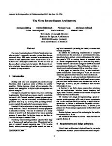
high performance characteristics and is typically unverifiable due to its complexity; b. if, during this process, the system state becomes in danger of violating a safety condition, the Safety Controller takes over; c. the exact switching behavior is implemented within a Decision Module. The advantage of the design is that high-performance components can be used without the requirement that they be fully verified. By maintaining a correct safety controller and decision module the properties about the safety of the composite system can be guaranteed. Thus, even if the complex controller is upgraded, is faulty or becomes infected with malware, we are still assured that the formal safety properties can never be violated and the plant remains safe. The Simplex architecture has been used to improve the safety of a fleet of remote-controlled cars [7], pacemakers [2] as well as advanced avionics systems [23]. Early Simplex designs had all three subsystems located in software – at the application-level. To guarantee complete system safety, however, other components such as any middleware and the operating system need to behave correctly. This requirement was relaxed in System-Level Simplex [2] by performing hardware/software partitioning on the system. In System-Level Simplex, the safety controller and the decision module are moved to a dedicated processing unit (an FPGA) that is different from the the microprocessor running the complex controller. We leverage this partitioning technique in S3A.
3. Threat Model We deliberately will not delve too deeply into specific threat models, since we believe that our techniques will work well for a broad class of attacks that modify the execution behavior of embedded code in safety-critical systems. Attacks similar to the ones mentioned in Section 2 can be caught by the mechanisms presented in this paper. Hence, code could be injected by any of the mechanisms described in that section – as long as the malicious entity tries to execute any code, we will be able to detect it. Hence, our threat model [14] is quite broad and can detect attacks such as: (a) physical attacks, ı.e. code injected via infected/malicious hardware; (b) memory attacks where attackers try to inject malicious code into the system and/or take over existing code; (c) insider attacks where the attackers try to gain control of the application/system by altering all or part of the program at runtime. We will, instead, focus on what happens after attackers perform any of the above actions in order to execute their code. Hence, we intend to show how our architecture is able to quickly detect this and keep the system(s) safe particularly the physical systems. Since we don’t care much about what executes and are more concerned with how long something executes, our “malicious entity” is a little more abstract as explained later in Sections 5.4.4 and 6.2.
Untrusted Controller: One important question is the use of an unverified (and hence, untrusted) complex controller in such systems. It is not that designers wish to use unverified controllers in such systems. Most such controllers that are intended to control anything but the simplest of systems are typically very complex and hard to verify. This is especially true if they must also achieve high levels of performance. Hence, there could be bugs and/or potential vulnerabilities in the system that attackers could exploit. Even if we assume that the controller is completely trusted, it can still be compromised (case in point – Stuxnet reprogrammed the controller in the PLC). Our technique can protect against any such intrusion, be it in trusted or untrusted controllers. System Upgrades: Another issue is what happens if the system must be updated and that process either (a) breaks the safety and timing properties of the system or (b) introduces malicious code. This is particularly important if such updates were to happen in a remote fashion. While these would be serious issues in most general-purpose or even mobile embedded systems (e.g. cell phones), it is not a problem for safety-critical systems. As mentioned in Section 1, such systems are rarely updated, if at all. Also, any updates have the following properties:
4. System Simplex Overview The Simplex Architecture [25] utilizes the idea of using simplicity to control complexity in order to safely use an untrusted subsystem in a safety-critical control system. A Simplex system, shown in Figure 1, consists of three main components: a. under normal operating conditions the Complex Controller actuates the plant; this controller has
4
Figure 1: Simplex Architecture
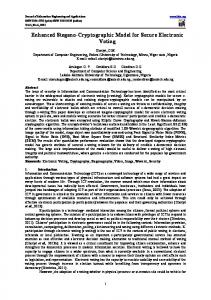
Figure 2: S3A Architecture
5.1. High Level Architecture
i. updates are never performed remotely – they are carried out by trusted engineers;
Figure 2 provides a high level overview of the system architecture. There is a Complex Controller that computes the control logic under normal operations. The computed actuation command is sent to the plant and sensor readings are produced and given to the controller to enable feedback control. There is also a Decision Module and Safety Controller in this architecture that are used not only to prevent damage to the plant in case of controller code bugs (as with the traditional Simplex applications) but also to prevent plant damage in the case of malicious actuation from attackers. We also have a Side Channel Monitor that examines the execution of the Complex Controller for changes in ‘expected’ behavior (in this paper it monitors the execution time of the Complex Controller to see if there is any deviation from what is expected). If the information obtained via the side channels differs from the expected model(s) of the system, the Decision Module is informed and control is switched to the Safety Controller (and an alarm can be raised). The types of side channels we can consider in a CPU-based embedded system include the execution time profiles of tasks, the number of instructions executed, the memory footprint and usage pattern or even the external communication pattern of the task. We will discuss timing side channels in more detail in the Section 5.2 and elaborate on the viability of the others in Sections 5.3 and 9. This approach is qualitatively more difficult to attack than a typical control system. An attacker not only has to compromise the main system, but she also has to replicate all the side channels that are currently being monitored. If the timing of the task execution is being monitored then the attacker must replicate the timing profile of a correctlyfunctioning system. If the cycle count is being observed, her attack must also be sure to execute for a believable number of instructions. Even if all the side channels match the expected models, the Decision Module will still monitor the plant state and, when malicious actuation occurs, prevent system damage. The effectiveness of the side channel early-detection methodology depends on two factors. First, the constructed model of each side channel should restrict valid system be-
ii. most updates are minor in that they only tune certain parameters and rarely, if at all, modify the control/timing structure of the code – hence they will not even modify the safety properties of the system and iii. any major changes will require extensive redesign, testing, etc. – hence the safety and real-time properties of the system must then be re-analyzed anyways. One other important point is that the Simplex architecture can actually support upgrades to the complex controllers [24] in a safe manner. Our application of Simplex in S3A, in this paper, has several significant differences compared with earlier approaches. In the past, the primary motivation to use Simplex was to aid in the verification of complex systems. In this work, we instead apply Simplex to protect against malware that has infected the complex controller. Another key difference is that previously the decision module’s behavior was determined completely by the physical state of the plant. In this work, we widen the scope of the “correct state” by using side channels from the computational part of the system, such as the timing properties of executing real-time tasks, in order to determine when to perform the switching. The Simplex decision module is now monitoring both, the physical system as well as the cyber state of the computational system.
5. Integrated Framework for Security: Secure System Simplex Architecture (S3A) We now present the Secure System Simplex Architecture (S3A) that prevents damage from malicious intrusions in safety-critical systems as well as aids in rapid detection through side-channel monitoring. In this section, we first elaborate on the high-level logical framework of the architecture. We then discuss aspects of the execution time-based side channels that we have implemented in our S3A prototype and then follow it up with details on how to implement such a system – from the hardware aspects to the OS modifications; from the timing measurements to the control system that we use to show the effectiveness of our approach.
5
havior (not easily replicable). Second, the side channel itself must be secure (not easily forgeable). These factors are implementation specific and will be discussed later in Section 5.4.
rations, scheduler events, etc.. Each of these is a candidate for benevolent side-channels that can be monitored to detect infections and would have to be individually detected and replicated by an attacker to maintain control in an infected system, thus qualitatively increasing the difficulty for future attackers. Additionally, the specific side channels used may vary depending on the type of system. E.g., in this paper, we focus on CPU-based real-time control systems. Other systems, e.g. PLC-based systems, would likely need to either monitor the side channels using different mechanisms or utilize a completely different (or additional) sets of side channels.
5.2. Timing Side Channels In this paper, we intend to secure a real-time embedded system. Therefore, we assume that the system has typical real-time characteristics, i.e. the system is divided into a set of periodic tasks managed by a real-time scheduler. Each task has a known execution time and each task periodically activates a job. The monitoring module maintains a real-time timing model of the system. Violations of this timing model occur when the, i. ii. iii. iv.
5.4. Implementation
job execution time is too large; job execution time is too small; job activation period is too large; or job activation period is too small.
We now describe a prototype implementation of S3A that we have created. The technical details of the prototype are listed in Table 1. We will elaborate on key aspects of our implementation in detail in the upcoming subsections. First, a hardware component overview is provided in Section 5.4.1. Then, the inverted pendulum hardware (our example ‘safety-critical control system’) setup is described in Section 5.4.2. The methodology for timing measurements of the control code is described in Section 5.4.3 and the methodology for timing-variability (‘malicious code’) tests is presented in Section 5.4.4. Section 5.4.5 gives essential details about the operating system setup during the measurements. Finally, Section 5.4.6 describes the specific design of the Decision Module and the timing Side Channel Monitor. Component Details Inverted Pendulum Quanser IP01 FPGA Xilinx ML505 Computer with Controller Intel Quad core 2.6 GHz Operating System Linux kernel ver. 2.6.36 Timing Profile Intel Timestamp Counter (rdtsc)
Additionally, the monitoring module needs to examine the execution of the idle task. This prevents a malicious attacker from allowing the real-time task to execute normally and perform malicious activity during idle time. Finally, the monitoring module should be cognizant of the system activities that may result in timing perturbations. In our prototype, we address two of these timing side channel requirements: monitoring the control task and the idle task. For rapid prototype development, we eliminate system noise (disable interrupts) while our control task is running to obtain a predictable timing environment3 rather than patching system interrupts in order to receive their timing information. In a real-time system the interrupts would be predictable and scheduled deterministically – hence we would be able to monitor them as well as other tasks. This addition, however, could be made to our prototype in the future. Execution times of the various real-time tasks in such systems are anyways obtained as part of system design by a variety of methods [32]. There is no extra effort that we have to perform to obtain this information. The worst-case, best-case and average-case behavior for most real-time systems is calculated ahead of time to ensure that all resource and schedulability requirements will be met during system operation. We use this knowledge of execution profiles to our advantage in S3A.
Table 1: S3A Prototype Implementation Details
5.3. Other Potential Time-based Side Channels In the assumed context of predictable real-time embedded control systems, several other side channels are available as part of the cyber state. These include the task activation periodicity, memory footprint, bus access times and du3
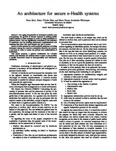
Figure 3: S3A Implementation Overview
Details in Section 5.4.5.
6
5.4.1. Hardware Components A high-level hardware design of our prototype is shown in Figure 3. The prototype hardware instantiates the logical Secure System Simplex architecture previously described in Section 5 and shown in Figure 2. In our implementation, we run the Complex Controller on the main CPU. The Complex Controller communicates with a trusted hardware component, an FPGA in this case, to perform control of an inverted pendulum. Sensor readings are obtained by the FPGA over the PCIe bus using memory mapped I/O. The actuation command, in turn, is written to the memory-mapped region on the FPGA. Additionally, timing messages in the form of memory-mapped writes are periodically sent to the FPGA based on the state of execution (at the start/end of the control task and periodically during the Idle Task). This creates a timing side channel that can be observed by a Timing Channel Monitor running on the FPGA. On the FPGA side, the Timing Channel Monitor will measure the time elapsed between timing messages from the Complex Controller to ensure that the execution conforms to an expected timing model. The Decision Module will periodically examine the output of the Timing Channel Monitor, the actuation command from sent by the Complex Controller from Shared Memory on the FPGA, the actuation command from the locally-running Safety Controller and the state of the plant from a Sensor and Actuator Interface and decide which controller’s actuation command should be used – the complex one on the CPU or the safe one on the FPGA. The actuation command is then output back to the Sensor and Actuator Interface. The interface then, through a digital-to-analog converter, actuates the Plant – in our case, an inverted pendulum. The Sensor and Actuator Interface also periodically acquires sensor readings through analog-to-digital converters and write their values to both shared memory accessible by the Complex Controller and to memory accessible by the trusted Decision Module and Safety Controller.
Figure 4: An inverted pendulum control system maintains an upright rod along a one-dimensional track. needed to directly connect the sensors and actuators to the FPGA hardware while the prebuilt setup requires a computer to do the data acquisition. We modified the system to redirect the sensor values and motor commands through an Arduino Uno microcontroller that communicates directly with the S3A FPGA through a serial cable. Although this change can potentially introduce latency into the system, we did not observe any issues with safely actuating the pendulum due to this small delay. The control code that manages the IP executes on a computer (Section 5.4.5 and Table 1). This control code executes at a frequency of 50 Hz. Note: The inverted pendulum has been used quite extensively in literature to be an appropriate example of a realtime control system [2, 25]. Hence we believe it would suffice to show an early prototype of our solutions. We are currently working on applying these techniques to other real control systems in conjunction with power vendors. 5.4.3. Timing The implementation of the complex controller for the inverted pendulum is fairly simple with very few branches and most loops being statically decidable4 . Hence it is fairly easy to calculate the execution time and number of instructions taken for such code. In our framework, we utilized simple dynamic timing analysis [32] methods to obtain an execution profile of the code. We used the Intel time stamp counter (rdtsc) [12] to obtain high resolution execution time measurements for the control code. The profile consisted of the ‘worst-case,’ ‘best-case’ and ‘steady-case’ numbers for the control code that was obtained by executing it multiple times on the actual computer where it would execute and measuring each set of executions. ‘Steady-case’ refers to the values obtained when the execution time has stabilized over multiple, repeated execu-
5.4.2. Inverted Pendulum We used an inverted pendulum (IP) as the plant that was being controlled. An inverted pendulum, like the one shown in Figure 4, is a classic real-time control challenge where a rod must be maintained in an upright position by moving a cart attached to the bottom of the pendulum along a one-dimensional track. There are two sensors to measure both the current pendulum angle as well as the cart position on the track and there is one actuator (the motor near the base of the pendulum) used to move the cart. Two safety invariants must be met: (1) the pendulum must remain upright (can not fall over) and (2) the cart must remain near the center of the track. The specific inverted pendulum we used in our testbed was based on the Quanser IP01 linear control challenge [11]. Our setup varies slightly from an off-the-shelf version of the Quanser IP01. The most important difference is that we
4
7
This is typical of most control code in safety-critical and real-time control systems – hence our implementation of the controller for the inverted pendulum is also similar.
tions – i.e. when the initial cold cache related timing dilation at the start of the experiments no longer occur. The control code was placed in a separate function and called in a loop. As part of our experiments, the loop was executed 1, 10, 100, 1, 000, 10, 000, 100, 000 and 1, 000, 000 times. During each of these scenarios, the total time of the loop as well as the times taken up during each individual iteration was measured. From these traces we were able to determine the maximum (worst-case), minimum (bestcase) and steady-case values for the execution time of the controller code. To reduce the noise from instrumentation and overheads of the loops, function calls, etc. we used the ‘dual-loop timing’ method: i.e., empty loops with only the measurement instrumentation were timed as a ’control’ experiment. The execution times obtained for these instrumentation-only loops were subtracted from the execution times for the loops with the control code. Interrupts (all interrupts including inter-processor interrupts) were disabled during the timing measurements. To reduce the timing effects of the operating system and other system issues we isolated our controller as best as we could as we will describe in Section 5.4.5. While we used simple measurement-based schemes for obtaining the execution profile for the control code in this paper, it does not preclude the use of other more sophisticated analysis techniques [19,32] to obtain better (and safer) timing estimates. This is especially true if the code is more complex than the one used for the inverted pendulum. In fact, the better the estimation methods, the better S3A will be able to detect anomalies and intrusions.
tion we used to best emulate a typical uni-processor embedded real-time platform. The CPU we used is an Intel Q6700 chip that has four cores and each pair of cores shares a common level two (last level) cache. We divided the four cores into two partitions: 1. the system partition running on the first pair of cores (sharing one of the two L2 caches) handles all interrupts for non-critical devices (e.g., the keyboard) and runs all the operating system activities and non realtime processes (e.g., the shell we use to run the experiments); 2. the real-time partition runs on the second pair of cores (sharing the second L2 cache). One core in the realtime partition runs our real-time tasks together with the driver for the trusted FPGA component; the other core is turned off so that we avoid any L2 cache interference among these two cores. 5.4.6. Detection In our implementation, detection of malicious code can occur in one of two ways. The decision module observes both (i) the physical state of the plant (by traditional Simplex) as well as (ii) the computation state of the system (based on timing messages; S3A). A violation of the physical model or the computational model can trigger the decision module to switch control to the safety controller on the FPGA. The physical model is monitored as described in previous work [3,4,25]. Based on a function of the track position and pendulum angle, the decision module may choose to switch over to the safety controller. The computational system is also monitored for violations of the expected timing model of the system. Both the control task and the idle task are monitored in order to periodically send timing messages to the FPGA. The FPGA contains an expected timing model of the system that is a finite state machine (FSM) running in hardware. When timing messages arrive, or timers expire, the finite state machine state can advance. If malicious code were to execute, it would have a limited window of time to replicate the tim-
5.4.4. Execution Time Variation To mimic the effect of code modification on timing, we insert extra code into the execution of the control loop function described in Section 5.4.3. Specifically, the extra code is a loop with a varying upper bound (i.e. 1, 10, 100) that performs multiple arithmetic operations (floating point and integer). The idea being that the extra time/instructions that execute will make it look like an intrusion has taken place. Our S3A system will then detect the additional execution, raise an alarm and transfer control to the simple controller on the FPGA. Note: As mentioned before, we are less interested in what kind of code executes “maliciously” because our detection scheme does not depend on this detail. We only need to check whether whatever is executing has modified the timing profile of the system. 5.4.5. System and OS Setup As stated in Table 1, we used an off-the-shelf multi-core platform running Linux kernel 2.6.36 for our experiments. Since we use a COTS system there are many potential sources of timing noise such as cache interference, interrupts, kernel threads and other processes that must be removed for our measurements to be meaningful. In this section we describe the configura-
Figure 5: FSM for Detecting Timing Model Violations 8
ing side channel before it was detected by the Simplex module. Generally speaking, monitoring the timing of a real-time system can be performed by maintaining state about each task in the system. Each task would have a two timers:
FSM about which side of the branch was taken. The FSM can now use this information to accurately track the execution of the program for all control constructs in the code.
6. Evaluation In this section we evaluate the Secure System Simplex architecture – first the we present timing results that we obtained by analysis of the controller code (Sections 6.1 and 6.2) – these values are used to form the profile of the execution behavior that is then used in intrusion detection mechanism on the FPGA. We then present the details of the intrusion detection in Section 6.3.
I. the first would enforce the execution time of the task II. the other will monitor periodic activation of the task Furthermore, a stack would be used to track task preemptions. Since typical real-time systems use priority-based execution, all task switches will be directly observable by the FPGA through task start/task end messages. For our specific prototype, we implemented, in hardware, the finite state machine on an FPGA as shown in Figure 5. In our system there are two tasks: (i) the idle task and (ii) the controller task. Since only a single task may be preempted (the idle task), we maintain a single variable as the call stack, stateI . Three timers are present: clkC and clkP maintain the execution time and period of the control task, clkI maintains the execution of the idle task. In the figure, clkC ticks while the control task is running (states C1 and C2 ) and clkI ticks while the idle task is executing (states I1 and I2 ). ClkP always ticks. The finite state machine is parameterized with six values: MustWaitC , CanWaitC , MustWaitI , CanWaitI , MustWaitP , and CanWaitP . These values are determined by the minimum and maximum time permitted between timing messages. The MustWait time indicates the minimum time that must elapse, whereas the CanTime indicates the jitter permitted between different iterations of the loop. To say it another way, MustWait is the minimum execution time of the task/idle loop/period, whereas (MustWait + CanTime) is the maximum execution time. In the finite state machine, initially the control task is running. State C1 is entered until clkC ticks from MustWaitC to 0. Then state C2 is entered. If clkC ticks from CanWaitC to 0 without the end task message, the control task has executed for too long and a timing violation occurs (indicated by the dotted arrow in state C2 ). Once the end control task message is received, the idle task begins to execute. Under normal operation, the state will change between I1 and I2 several times, until the control task is reactivated and state C1 is again entered. Any messages that arrive without explicit transitions in the timing FSM are interpreted as errors in the prototype and trigger decision module to switch to the safety controller. Additionally, the dotted transitions in the FSM are timing violations that also trigger the decision module to take corrective action. The FSM can also be used to tightly track the execution behavior of the code for more sophisticated controllers, e.g. if the control code has many branches, function calls, etc. For instance, when the control code reaches a branch that affects the overall execution time, a message can be sent to the
6.1. Timing Results and Execution Profile
Figure 6: Summary of the Timing Results Figure 6 shows a high level summary of the timing experiments used to obtain the execution profile of the complex controller code that executes on the computer (Figure 2). We used dynamic timing analysis techniques to obtain the worst, best and steady state execution times for this code. The x-axis represents the number of times the controller code was repeatedly executed: from 1 to 1, 000, 000 in steps of 10. The y-axis represents the execution time in cycles. Each grouping of vertical lines represents the ‘worstcase’, ‘steady-state’ and ‘best-case’ execution times for that experiment. ‘Steady-state’ refers to the execution time when successive executions of the controller code resulted in the same execution time – i.e. the situation when the execution reached a steady state. This is compared to the first few iterations, when cache and other hardware effects would result in a higher variance in the execution time of the code – the ‘worst-case’ numbers in the graph are usually from these first few iterations before the system effects (in particular the cache) have settled down. This is the reason why there exists a slightly larger difference between the worstcase and best-case numbers. Each vertical bar is split into two parts – the lower part shows the instrumentation overhead for that experiment5 ,
9
band at the top of the range (i.e. around the 14K value). This narrow band of increased execution times for some experiments is due to latent system effects that we were not able to remove. The main culprit is the last level cache that, in this architecture, uses a random replacement policy. Hence, every once in a while a few of our controller’s cache lines are evicted by periodic kernel threads that we could not easily disable (since we are running a COTS operating system) and these iterations take a few hundred cycles extra (anywhere from 500 − 900) to execute. With a more predictable cache replacement policy, like the ones used in hard realtime systems, we would not see this behavior. To prove this theory we ran the same measurements on a PowerPC that uses psuedo-LRU (Last Recently Used) cache replacement policy in its last level and all the points are clustered into a single band. In fact, with LRU, tasks would not evict each other cache’s lines, unless the cache is not big enough to fit them at the same time6 Figure 7 also shows a few sporadic experiments exhibiting much higher execution times. Again, this is due to system effects, and in particular, contention on the bus when communicating with the FPGA. As explained in Section 5.4.1, the complex controller reads and writes messages to and from the FPGA to control the pendulum and to send the timing messages. Many a time, while the complex controller is waiting for data from the inverted pendulum (angle and track position) that arrives on the common bus, the incoming messages experience unpredictable delays. These delays are due to bus contention among the FPGA and other peripherals sharing the same bus. To prove that the communication with the FPGA was the cause of these effects, we conducted timing experiments where the FPGA was switched off and all calls to communicate with it (read/write) resulted in null function calls. Figure 8 shows the results of these experiments for the 100, 000
while the top is the part that represents the pure timing for the control code only. We also see that the instrumentation overhead is almost the same across all experiments – oscillating between 260 and 270 cycles for all experiments. As seen in the graph, the steady state and best-case values are very close, not just within the same experiment, but across experiments. The largest difference between the two is 360 cycles for the n = 100, 000 experiment. This just shows that our assumption that controller codes in safetycritical systems are simple and have little variability is valid. This lack of variability is also evident from the fact that the worst-case execution cycles, across experiments, do not show much variance. The worst-case values for the last experiment (1, 000, 000) has a slightly higher value of 16, 560 and this can be chalked down to the initial cold cache and other system effects. Figure 7 shows the execution profile for one timing experiment in particular – that of 100, 000 iterations. The xaxis is the iteration number while the y-axis is the number of cycles for each iteration. As this figure shows, the first few iterations take a little longer (around 17K cycles) and then most of the execution stabilizes to within a narrow band of: 1, 590 cycles = 14, 660 − 13, 070 i.e. ∼ 0.6 µs at 2.67 GHz Hence, this band will define the ‘accepted range’ of values that the FPGA will use to check for intrusions. Any execution that changes the steady state execution time by more than this narrow range will be caught by the FPGA. In fact, the FPGA will catch variance in either direction – i.e. an increase as well as a decrease in execution time. The graph also shows that while the majority of execution times fall within a small band at the lower end of the above mentioned range, some values also fall into a narrow 5
6
As explained in Section 5.4.3, we used dual-loop timing techniques to obtain the overheads due to the instrumentation.
Figure 7: Execution Profile for 100,000 iterations
If this is the case, we just have to account for it, when we compute the execution time for each task.
Figure 8: Execution Profile (100,0000) without FPGA
10
over to the simple controller executing on the FPGA. Note: Since we don’t really care what executes as part of malicious code and intend to only catch variations in execution time, we only mimic the increased execution time effects by the methods discussed in this section.
iterations point. This experiment highlights two important points: • the random spikes at higher values no longer exist, thus showing that the bus contention due to communication with the FPGA was the main cause of the spikes • the same ‘double-band’ of execution results also appears here; the interesting fact is that the gap between the bands is almost exactly identical to that of Figure 7, thus providing more evidence to the fact that the cache (and its replacement policy) is the culprit.
6.3. Intrusion Detection In this section, we describe the evaluation of our timing side channel intrusion detection technique. First, we describe measurements of the timing of key aspects of our overall architecture. Then, we demonstrate the early detection of malicious code execution using the timing side channel approach compared with monitoring the plant state only (say, by used of traditional Simplex). The results of our intrusion detection measurements are summarized in Table 2. Our first timing measurement was to check the overhead of sending timing messages to the FPGA. Although the message itself takes time to propagate through the PCIe bus to the FPGA, the CPU is not stalled during this time. By using the time stamp counter we measured the overhead on the CPU for sending a single timing message to be 130 cycles (50 nanoseconds). This time is extremely small and therefore each process could realistically send multiple messages during a single iteration of each control loop to reduce the time an attacker has to replicate the timing side channel. Another advantage of having multiple timing messages per iteration is that if the program contains branches, we could communicate to the FPGA timing monitor (at run-time) information about which branch was taken thus allowing for tighter monitoring of the timing requirements in the timing model FSM. The second timing measurement we did was to quantify the jitter of the timing messages through the interconnect going to the FPGA. We performed this measurement by recording the difference between the arrival of the start control iteration timing message and the end control iteration timing message, in the FPGA, over several thousand iterations of the control loop. The reason for this jitter is twofold: (a) one source is the jitter of the execution time itself (the difference between the minimum and maximum execution time as shown in Figure 5) and (b) the second source of jitter is the varying time of message propagation through the PCIe bus. Since our testbed was a multicore system, processes running concurrently on other cores as well as other independent bus masters such as peripherals may cause interference on the shared interconnect. Although, as we already said, in a deployed real-time control system, such noise would not be present or at least bounded. On the other hand, our testbed was essentially an off-the-shelf installation of Linux running on COTS hardware. Nonetheless, we measured the typical timing variation caused by the interconnect to be about 0.6 microseconds, or less than one eighth of the iteration time of a single control iteration in this case.
Such issues could be avoided in an actual hard real-time system instead of the COTS-based experimental setup that we use here. In fact, a hard real-time system would use a more predictable bus, or other techniques [5], that allows designers to bound I/O contention and avoid random spikes.
6.2. Malicious code Execution Results
Figure 9: Execution Cycles for Malicious Code execution We introduce “malicious code” by inserting extra instructions (Section 5.4.4) – i.e. a loop of variable size within the complex controller code. The upper bounds for the malicious loop are one of 1, 10, 100 – we stopped at the upper limit of 100 since anything over this value would put the execution of the “infected” control code over the real-time period of the task. Also, as we will see soon, even these small additional increases in execution times will be caught by the monitoring framework of S3A. Figure 9 shows the execution time (in cycles on the yaxis) taken up by the code for value of the malicious loop values (x-axis). The final bar in the graph represents the “base,” i.e. the number of execution cycles taken up by the controller code without any malicious loop. As expected, the values for the malicious code increases significantly with each increase in the loop bound. Even the smallest sign of the presence of the malicious loop puts it outside of the narrow range (0.6µs) explained in Section 6.1. Hence, even this will be caught by S3A and control will be transferred
11
Measured Quantity Control Task Execution Time for single iteration Interconnect Extra Jitter Enforced Iteration Time Timing Anomaly Detection Time (for Inverted Pendulum system) Vanilla Simplex Anomaly Detection Time Timing Message CPU Overhead
Time (µs) 4.8 - 5.4
periment, we were able to detect an intrusion after 5 control iterations, or 100 milliseconds. It is clear that the use of timing side channels enables significantly faster detection of security vulnerabilities in real-time control systems: over four orders of magnitude faster than with traditional Simplex.
∼ 0.6 4.6 - 5.7 5.7
7. Limitations 10,000 0.05
The proposed S3A Architecture is not a silver bullet for intrusion detection in embedded control systems and does have some practical restrictions which may limit its applicability. Firstly, in order to use the Secure System Simplex Architecture in a real system, the system needs to be designed with the architecture in mind. If there is no way to insert a decision module between the controller and the plant then the architecture can not be used. While this is a limitation for some existing systems, we think that the design of future systems could provision for such techniques; after all it is never a bad idea to consider security aspects when designing a new system. One concern regarding the correctness of the approach is making sure that an attacker cannot easily replicate our side channels. E.g., if a processor instruction count side channel is created by naively sending the current instruction count value to the the Monitoring Module then a malicious entity could easily store and then replay these values. These types of restrictions could be overcome with minor modifications to the processor architecture. In this instance, allowing the FPGA to directly access the instruction count without involving explicit communication from the CPU would eliminate the possibility of spoofing. Additionally, for each side channel, a model of the correct behavior must be created that would restrict a malicious program. For our timing side channel, one problem could be that the execution of the task has too much of a difference between the minimum and maximum execution times to provide real restrictions on system behavior. While this could be the case in general purpose systems, it is not very likely in CPS with real-time constraints. Even so, this could be overcome at runtime by having each timingbehavior-modifying branch point send a timing message to the FPGA indicating what path was taken. This would permit an extremely tight bound to be placed on the execution time at the expense of a more complicated state machine to detect timing anomalies. The construction and tuning of the timing parameters of the state machine is also currently a manual process. We believe this could eventually become a more automatic step in the procedure by performing a compile-time analysis of the control flow graph of the code – indicating where to send the timing messages and using run-time analysis to perform precise timing measurements. The implementation of the trusted FPGA hardware in our framework must be correct for the system to be secure. This
Table 2: Measured Timings during Intrusion Detection Any malicious code that increases the execution time of the task by more than this amount would be detected by the FPGA timing monitor. As shown in Table 2, we can now detect an intrusion using the timing-based side channel within 5.7µs and anything that changes the timing by 0.6µs would be caught. Furthermore, we could also add multiple timing messages in each control iteration (since the CPU message overhead is so low) to further reduce the maximum intrusion detection delay. In Table 2, the control task execution time was obtained from from the execution time measurements from Section 6.1. The values in the table are in absolute time which was converted from the cycle count measurements we performed. Hence, the 4.6 − 5.7µs value for the ‘Control Task Execution Time’ is obtained from the (approx.) 13, 000 − 14, 000 cycles that we discussed in Section 6.1 and Figure 7. Due to the extra jitter caused by the interconnect, the enforced iteration time is expectedly larger than the measured control task execution time. The maximum enforced iteration time, 5.7µs, is the maximum time the experimental framework can proceed without a timing message before the safety controller takes over. To state it another way, in the FSM in Figure 5, the runtime value of M ustW aitC is 4.6µs, and the runtime value of CanW aitC is about 1.1µs (mustW aitI and canW aitI are much lower). Given those numbers, the side-channel monitor FSM will detect a missed timing message within 5.7µs, i.e. the detection time reported. We now compare the early detection of malicious code through timing side channels with the behavior of the decision module of the S3A with the situation when it only monitors the plant state (vanilla Simplex). In the timing side channel version, as discussed above, the maximum time that can proceed before without valid timing messages is 5.7µs. For the vanilla Simplex version, we experimentally measured the amount of time needed to detect an intrusion. After taking control of the system, we immediately tried to destabilize the pendulum by sending a maximum voltage value in the direction which would most quickly collapse the pendulum (in order to see a lower bound on the detection time when plant state is monitored alone). In this ex-
12
may seem like we have just moved the problem over to securing the FPGA system instead of the main system, but this is not exactly the same for the following reason: the FPGA and Safety Controller only need to maintain the safety of the plant. The Complex Controller, on the other hand, can perform useful work with the plant so any upgrades will be made to the Complex Controller and not to the FPGA’s safety logic. The Complex Controller’s timing profile would need to be upgraded but that could be done in a restricted way to prevent modification to the Safety Controller and Decision Module. Of course, we should not permit FPGA reconfiguration at runtime and the trusted hardware platform could even be created on an Application-Specific Integrated Circuit (ASIC) instead of an FPGA in order to enforce this. One issue related to the use of FPGAs in such systems is that sometimes the complex controller might require the use of complex floating point calculations and such floatingpoint computation units are typically not present on FPGAs since they use up significant area. The FPGA in our architecture is used as a rapid prototype of the trusted simplex component. A deployment implementation would likely use a trusted microcontroller along with any capabilities (floating point unit) that are needed for the safety controller, decision module, and side-channel monitor. Also, as mentioned before, the FPGA will only host the safety controller that maintains bare functionality. Hence, it is unlikely that it will need to perform fancy floating point calculations. Finally, the original Simplex, in general, can only protect the systems from properties known up front to result in unsafe states. E.g. in Stuxnet, the malicious controller would actuate the plant motor for periods at very high frequencies and then for periods at very low frequencies in order to damage the motors. If the Decision Module was not monitoring this property, such unsafe actuation would still proceed to the plant.
The trusted computing engine (TCE) [13] as well as the reliability and security engine (RSE) [14] also use secure co-processors to execute security-critical code and to monitor the access of critical data. During setup the securitycritical application is loaded on the TCE and then access to it is monitored during runtime. To detect other security violations, compile-time analysis is performed to determine the critical data, the dataflow and what parts of the code are allowed to access this data. At runtime, RSE monitors all of this information to see if unauthorized instructions/programs access this critical data. While these techniques could be combined with S3A (since they are more about intrusion prevention), we don’t need to know the information about what data is critical or even touch the source code. We detect intrusions by observing the innate characteristics of the program at runtime. The IBM 4758 secure co-processor could also be used to perform intrusion detection [33]. This work contains a CPU, separate memory (volatile and non-volatile) along with cryptographic accelerators and comes wrapped in a tamper-responding secure boundary. The main methods employed for intrusion detection included checking the system for invariants (one example was that a normal user’s ‘uid’ should never change to root) and detecting related violations. Also, they used it to execute the virus checking programs since it couldn’t be tampered with. While we could adapt this processor for use with our architecture, the main difference from S3A lies in the fact that we employ the inherent characteristics of the program to detect intrusions, especially in the CPS domain; also coupling with the System Simplex mechanism increases the robustness of the overall system. FlexCore [8] uses a reconfigurable fabric to implement monitoring and book-keeping functions. It can be used to implement bookkeeping mechanisms and specific security methods such as array bounds checking, uninitialized memory checks, dynamic information flow tracking, etc. in the reconfigurable hardware. While many of these functionalities could be implemented in S3A, the main difference with FlexCore lies in the fact that we (a) don’t need to know what types of attacks are taking place (as long as it modified the execution time behavior of our code) and (b) don’t need to analyze the program structure/data as will be the case with FlexCore. Pioneer [22] uses sophisticated checksum code and its execution time information to establish safe remote execution on an untrusted computer. The checksum code is carefully designed so that any malicious modification will result in increased execution time that will be detected by the requesting computer. While their goal is remotely executing arbitrary code safely on untrusted computers, our goal is to detect the behavioral changes of known code running on potentially compromised computers.
8. Related Work The closest work to S3A is by Zimmer et. al. [34]. They use worst-case execution time (WCET) information to detect intrusions in hard real-time systems by instrumenting the tasks and schedulers and periodically checking whether the execution has gone past the expected WCET values. Our work is more focused on detecting intrusions in realtime control systems and ensuring that the plant remains safe even if the intruder is able to bypass all the detection/security mechanisms. Also, in our work, the system remains safe even if the intruder gains root privileges to the system – the work by Zimmer et. al. cannot withstand this level of intrusion since an attacker with root privileges can bypass all the checking mechanisms. Also, our checking/monitoring is performed by a trusted hardware component that is separate from the main system thus increasing the overall robustness of the architecture.
13
References
TVA [10] provides guarantees that the software running on the computer is safe in conjunction with a hardware trusted component (TPM). While they also use trusted hardware, our approach differs in that we’re not trying to prevent intrusions or attacks. Our aim is to detect these quickly and maintain the physical safety of the plant.
[1] M. Abrams and J. Weiss. Malicious control system cyber security attack case study – maroochy water services. http://crc.nist. gov/groups/SMA/fisma/ics/documents/ Maroochy-Water-Services-Case-Study_ report.pdf, 2008. [2] S. Bak, D. K. Chivukula, O. Adekunle, M. Sun, M. Caccamo, and L. Sha. The system-level simplex architecture for improved real-time embedded system safety. In RTAS ’09: Proceedings of the 2009 15th IEEE Real-Time and Embedded Technology and Applications Symposium, pages 99–107, Washington, DC, USA, 2009. IEEE Computer Society. [3] S. Bak, A. Greer, and S. Mitra. Hybrid cyberphysical system verification with simplex using discrete abstractions. In Proceedings of the 2010 16th IEEE Real-Time and Embedded Technology and Applications Symposium, RTAS ’10, pages 143–152, Washington, DC, USA, 2010. IEEE Computer Society. [4] S. Bak, K. Manamcheri, S. Mitra, and M. Caccamo. Sandboxing controllers for cyber-physical systems. 2nd ACM/IEEE International Conference on Cyber-Physical Systems (ICCPS), 2011. [5] E. Betti, S. Bak, R. Pellizzoni, M. Caccamo, and L. Sha. Real-time i/o management system with cots peripherals. Computers, IEEE Transactions on, PP(99):1, 2011. [6] S. Checkoway, D. McCoy, B. Kantor, D. Anderson, H. Shacham, S. Savage, K. Koscher, A. Czeskis, F. Roesner, and T. Kohno. Comprehensive experimental analyses of automotive attack surfaces. In USENIX Security, Aug 2011. [7] T. L. Crenshaw, E. Gunter, C. L. Robinson, L. Sha, and P. R. Kumar. The simplex reference model: Limiting faultpropagation due to unreliable components in cyber-physical system architectures. In RTSS ’07: Proceedings of the 28th IEEE International Real-Time Systems Symposium, pages 400–412, Washington, DC, USA, 2007. IEEE Computer Society. [8] D. Y. Deng, D. Lo, G. Malysa, S. Schneider, and G. E. Suh. Flexible and efficient instruction-grained run-time monitoring using on-chip reconfigurable fabric. In Proceedings of the 2010 43rd Annual IEEE/ACM International Symposium on Microarchitecture, MICRO ’43, pages 137–148, Washington, DC, USA, 2010. IEEE Computer Society. [9] N. Falliere, L. Murchu, and E. C. (Symantec). W32.stuxnet dossier. http://www.symantec. com/content/en/us/enterprise/media/ security_response/whitepapers/w32_ stuxnet_dossier.pdf, 2011. [10] T. Garfinkel, B. Pfaff, J. Chow, M. Rosenblum, and D. Boneh. Terra: A virtual machine-based platform for trusted computing. ACM SIGOPS Operating Systems Review, 37(5):193–206, 2003. [11] Q. Industrial. Inverted pendulum [ip] linear. Quanser IP01, 2011. [12] Intel. Using the RDTSC instruction for performance modeling. www.ccsl.carleton.ca/˜jamuir/ rdtscpm1.pdf.
Other related work is the use of PRET (precision timed machines) to detect and protect against side-channel attacks [17]. While their work is focused on preventing attacks based on side-channels we use them for a benevolent purpose – to improve the overall security of the system.
9. Conclusions and Future work In this paper we presented a new framework named Secure System Simplex Architecture (S3A) that enhances the security and safety of a real-time control system such as a SCADA plant. We use a combination of trusted hardware, benevolent side-channels, OS techniques and the intrinsic real-time nature (and domain-specific characteristics) of such systems to detect intrusions and prevent the physical plant from being damaged. We were able to detect intrusions in the system in less than 6 µs and changes of less than 0.6 µs – time scales that are extremely hard for an intruders to defeat. This paper also shows that even if an attacker is able to bypass all security/intrusion detection techniques, the actual plant will remain safe. Another important characteristic of these techniques is that there are no modifications required in the source code. We believe that the novel techniques and architecture presented in this paper will significantly increase the difficulty faced by wouldbe attackers thus improving the security and overall safety of such systems. The intrusion detection capabilities of S3A can be further enhanced by monitoring multiple side channels and/or improving the predictability of the system. E.g., with the current implementation, the more the system is predictable, the less will be the jitter measured by the timing analysis, the tighter can be the execution time range enforced by the Secure Simplex. For future work we plan to investigate other side channels. For instance, instruction count can be used in S3A so that a deviation in the number of instructions can be treated as an indication of the existence of malicious code. Fairly small modifications in the processor could enable trusted hardware to access the CPU instruction counter, thus enabling an instruction-based side channel. Finally, a predictable execution model like PREM [21], can also considerably enhance system predictability and hence, the precision of timing side channel. In fact, PREM can almost eliminate the jitter in execution time jitter that results from bus and memory contentions.
14
[27] T. Smith. Hacker jailed for revenge sewage attacks. http://www.theregister.co.uk/2001/10/ 31/hacker_jailed_for_revenge_sewage, October 2001. [28] Symantec. Stuxnet: A breakthrough. http: //www.symantec.com/connect/blogs/ stuxnet-breakthrough, 2010. [29] US-CERT. ICS-alert-10-239-01: Dynamic library loading vulnerability in microsoft-based applications. Aug. 2010. [30] US-CERT. ICSA-10-201-01C: USB malware targeting Siemens control software. http://www.us-cert. gov/control_systems/pdf/ICSA-10-201-01. pdf, 2010. [31] US-CERT. ICSA-10-272-01: Primary stuxnet indicators. Aug. 2010. [32] R. Wilhelm, J. Engblohm, A. Ermedahl, N. Holsti, S. Thesing, D. Whalley, G. Bernat, C. Ferdinand, R. Heckmann, T. Mitra, F. Mueller, I. Puaut, P. Puschner, J. Staschulat, and P. Stenstrom. The worst-case execution time problem — overview of methods and survey of tools. ACM Transactions on Embedded Computing Systems, 7(3):1–53, Apr. 2008. [33] X. Zhang, L. Van Doorn, T. Jaeger, R. Perez, and R. Sailer. Secure coprocessor-based intrusion detection. Proceedings of the 10th workshop on ACM SIGOPS European workshop beyond the PC EW10, page 239, 2002. [34] C. Zimmer, B. Bhatt, F. Mueller, and S. Mohan. Time-based intrusion detection in cyber-physical systems. In International Conference on Cyber-Physical Systems, 2010.
[13] R. K. Iyer, P. Dabrowski, N. Nakka, and Z. Kalbarczyk. Reconfigurable tamper-resistant hardware support against insider threats: The trusted illiac approach. 39:133–152, 2008. 10.1007/978-0-387-77322-3 8. [14] R. K. Iyer, Z. Kalbarczyk, K. Pattabiraman, W. Healey, W.-M. W. Hwu, P. Klemperer, and R. Farivar. Toward application-aware security and reliability. IEEE Security and Privacy, 5:57–62, 2007. [15] K. Koscher, A. Czeskis, F. Roesner, S. Patel, T. Kohno, S. Checkoway, D. McCoy, B. Kantor, D. Anderson, H. Shacham, and S. Savage. Experimental security analysis of a modern automobile. In Security and Privacy (SP), 2010 IEEE Symposium on, pages 447 –462, may 2010. [16] C. Li, A. Raghunathan, and N. Jha. Hijacking an insulin pump: Security attacks and defenses for a diabetes therapy system. In e-Health Networking Applications and Services (Healthcom), 2011 13th IEEE International Conference on, pages 150 –156, june 2011. [17] I. Liu and D. McGrogan. Elimination of side channel attacks on a precision timed architecture. Technical Report UCB/EECS-2009-15, EECS Department, University of California, Berkeley, Jan 2009. This a class project report describing early work on eliminating side channel attacks using PRET. [18] R. McMillan. Insider charged with hacking california canal system. http://www.computerworld.com/ s/article/print/9050098/Insider_charged_ with_hacking_California_canal_system, November 2007. [19] S. Mohan and F. Mueller. Hybrid timing analysis of modern processor pipelines via hardware/software interactions. In IEEE Real-Time Embedded Technology and Applications Symposium, pages 285–294, 2008. [20] N. A. E. R. C. (NERC). Jan-june 2009 disturbance index. http://www.nerc.com/files/ disturb09-January-June.pdf, 2009. [21] R. Pellizzoni, E. Betti, S. Bak, G. Yao, J. Criswell, M. Caccamo, and R. Kegley. A predictable execution model for cots-based embedded systems. In Proceedings of the 17th Real-Time and Embedded Technology and Applications Symposium, Chicago, IL, USA, April 2011. [22] A. Seshadri, M. Luk, E. Shi, A. Perrig, L. van Doorn, and P. Khosla. Pioneer: verifying code integrity and enforcing untampered code execution on legacy systems. ACM SIGOPS Operating Systems Review, 39(5):1–16, 2005. [23] D. Seto, E. Ferreira, and T. F. Marz. Case study: Development of a baseline controller for automatic landing of an f-16 aircraft using linear matrix inequalities (lmis). Technical Report Cmu/ sei-99-Tr-020. [24] D. Seto, B. Krogh, L. Sha, and A. Chutinan. Dynamic control system upgrade using the simplex architecture. IEEE Control Systems, 18(4):72–80, Aug. 1998. [25] L. Sha. Using simplicity to control complexity. IEEE Softw., 18(4):20–28, 2001. [26] L. Sha, R. Rajkumar, and M. Gagliardi. The simplex architecture: An approach to build evolving industrial computing systems. In The Proceedings of The ISSAT Conference on Reliability, 1994.
15